Language selection

Search

Patent 2436755 Summary

Third-party information liability

Some of the information on this Web page has been provided by external sources. The Government of Canada is not responsible for the accuracy, reliability or currency of the information supplied by external sources. Users wishing to rely upon this information should consult directly with the source of the information. Content provided by external sources is not subject to official languages, privacy and accessibility requirements.

Claims and Abstract availability

Any discrepancies in the text and image of the Claims and Abstract are due to differing posting times. Text of the Claims and Abstract are posted:

  • At the time the application is open to public inspection;
  • At the time of issue of the patent (grant).
(12) Patent: (11) CA 2436755
(54) English Title: METHOD OF CONTINUOUS PRODUCTION OF METAL WIRES
(54) French Title: METHODE DE PRODUCTION CONTINUE DE FILS METALLIQUES
Status: Deemed expired
Bibliographic Data
(51) International Patent Classification (IPC):
  • B21C 3/06 (2006.01)
  • B21C 1/00 (2006.01)
  • B21C 1/04 (2006.01)
  • B21C 23/08 (2006.01)
  • B21C 25/02 (2006.01)
  • B21C 25/08 (2006.01)
  • B21C 37/04 (2006.01)
(72) Inventors :
  • LOTTNER, GUENTER (Germany)
(73) Owners :
  • NEXANS (France)
(71) Applicants :
  • NEXANS (France)
(74) Agent: ROBIC
(74) Associate agent:
(45) Issued: 2009-08-04
(22) Filed Date: 2003-08-07
(41) Open to Public Inspection: 2004-02-13
Examination requested: 2006-05-16
Availability of licence: N/A
(25) Language of filing: English

Patent Cooperation Treaty (PCT): No

(30) Application Priority Data:
Application No. Country/Territory Date
102 37 027.3 Germany 2002-08-13

Abstracts

English Abstract

In a method for continuous production of metal wires, the cross section of a round metal wire is reduced in one or more stages. To do so, the metal wire is shaped in a bore that is open on one side to form a flat wire at least in the last stage.


French Abstract

Dans une méthode de production en continu de fils de métal, la section transversale d'un fil de métal rond est réduite en une ou plusieurs étapes. Pour ce faire, le fil de métal est formé dans un trou ouvert d'un côté pour former un fil plat au moins à la dernière étape.

Claims

Note: Claims are shown in the official language in which they were submitted.


4

WHAT IS CLAIMED IS:


1. A method of continuous production of metal wires, whereby the cross section

of a bare metal wire is reduced in several stages up to a last stage, wherein
in the
last stage, a shaping of the bare metal wire is performed to form a flat wire
by
drawing the bare wire through a drawing die, the drawing die having a bottom
part
(2) and a top part (3) to delimit a bore, a distance from the top part (3) to
the bottom
part (2) being adjustable, the shaping to form the flat wire is performed
without any
significant reduction in cross section.


2. The method according to claim 1, wherein the flat wire has a maximum ratio
of thickness to width of 1:5.


3. The method according to claim 1, wherein the round metal wire is shaped to
form the flat wire in up to five shaping steps.


Description

Note: Descriptions are shown in the official language in which they were submitted.


CA 02436755 2008-07-30

1
METHOD OF CONTINUOUS PRODUCTION OF METAL WIRES
This invention relates to a method of continuous production of metal wires.

In the industry, in particular in the electronics industry, there is a great
demand for flat metal wires.
A flat wire is generally understood to mean a wire having a rectangular cross
section with a much
smaller thickness in relation to its width.

Production of sucli flat wires is performed by rolling round wires in the
traditional manner. The
starting material is usually so-called proportional wires, which can be
manufactured inexpensively
by the continuous casting and rolling method.

The round wires are first drawn down on a multiple drawing machine and are
then shaped to form
the flat wire in a downstream rolling operation.

The disadvantage of this procedure is that the rolling is relatively slow
because of the high heat
evolved. In addition, the rolling operation is quite maintenance intensive.

The object of the present invention is to provide a method with which flat
wires can be produced
economically from round wires in one operation.

According to the present invention, there is provided a method of continuous
production of metal wires, whereby the cross section of a bare metal wire is
reduced
in several stages up to a last stage, wherein in the last stage, a shaping of
the bare
metal wire is performed to form a flat wire by drawing the bare wire through a
drawing die, the drawing die having a bottom part and a top part to delimit a
bore, a
distance from the top part to the bottom part being adjustable, the shaping to
form
the flat wire is performed without any significant reduction in cross section.

The essential advantage of this invention can be seen in the fact that the
working stage of "flatteiung"
is integrated into the drawing operation, which is performed at a high speed.
This does not produce
a flat wire with an exactly rectangular cross section, but instead it yields a
wire having a cross section
in which the long sides are parallel to one another and the narrow sides are
rounded.

The flat wires that can be produced according to the teaching of this
invention are preferably used
as shielding wires for electric cables and lines. At the same metal weight,
they are capable of
covering a larger area and thus lead to considerable savings in terms of the
weight and cost of the
cables and lines.


CA 02436755 2008-07-30

2
The flat wires can be processed to a braid in braiding installations, in
particular if the ratio of the
thickness to the width of the flat wires amounts to less than 1:5.

In addition to the possibility of performing the shaping of the round wire to
a flat wire in the same
operation as the drawing of the round wire more or less as the last step,
there is also the possibility
of shaping the round wire to form a flat wire following the drawing operation
as part of the process
of rewinding the wire from one spool to another.

Other advantageous embodirrients of this invention are described in the
following
description.

This invention is explained in greater detail on the basis of the exemplary
embodiments diagrained
schematically in Figures 1 and 2.

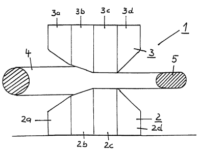
Figure 1 shows a sid"e view of a drawing die 1 composed of a bottom part 2 and
a top part 3. The
bottom part 2 is preferably arranged in a fixed position on a substrate. The
top part 3 is also fixed
in its position in relation to the bottom part 2, but the distance from the
bottom part 2 to the top part
3 is adjustable.

The bottom part 2 and the top part 3 each have an inlet area 2a and 3a, thus
providing cooling for
the die 1. As seen in the direction of production (from left to right in the
figure), there then follow
the shaping area 2b.and 3b and the calibration area 2c and 3c, which determine
the thickness of the
flat wire. The outlet area is labeled as 2d and 3d.
As shown in Figure 1, in a drawing operation, the round wire 4 is gradually
shaped to yield a flat
wire 5 by the die 1, which consists of the bottom part 2 and the top part 3.
Due to the fact that the
die I is open toward the sides, the cross section of the flat wire is not
rectangular, but instead the
narrow sides are curved, which results in the shaping being a flattening or a
squeezing operation in
the actual sense.

Figure 2 shows a view of the die I in the direction opposite the manufacturing
direction. It is clearly
discernible here that the die I does not have a closed bore.

To present lateral displacement of the round wire 4 and/or the flat wire 5,
guides (not shown) may
be provided in front of and/or behind the die 1.

The device for implementing the method comprises a run-off device for the
round
metal wire, a plurality of dies arranged one after the other and a draw-off
disk,


CA 02436755 2008-07-30

2a
which is provided downstream from each die and has an adjustable drive,
characterized in that at least the last die is composed of a bottom part (2)
and a
top part (3), and the distance from the top part (3) to the bottom part (2) is
adjustable.

The die 1 shown in Figures 1 and 2 may be used as the last drawing stage in a
continuous multiple drawing machine, in which case a plurality of dies
according
to this invention may also be arranged


CA 02436755 2003-08-07

3
in succession to permit gradual shaping to yield the final cross section of
the flat wire 5. This shaping
may be associated with a reduction in cross section, but the cross sections of
the round wire and the
flat wire may also be of the same order of magnitude.

The die according to this invention may also be used in rewinding wire from a
first spool to a second
spool, in which case the round wire being drawn off the first spool is shaped
to form the flat wire,
which is then wound onto the second spool.

In addition to the advantages mentioned above, this invention also has the
decisive advantage that
the surfaces of the bottom part 2 and the top part 3, which are necessary for
the shaping, can be
polished much more easily than is the case with dies having a closed bore.

Representative Drawing
A single figure which represents the drawing illustrating the invention.
Administrative Status

For a clearer understanding of the status of the application/patent presented on this page, the site Disclaimer , as well as the definitions for Patent , Administrative Status , Maintenance Fee  and Payment History  should be consulted.

Administrative Status

Title Date
Forecasted Issue Date 2009-08-04
(22) Filed 2003-08-07
(41) Open to Public Inspection 2004-02-13
Examination Requested 2006-05-16
(45) Issued 2009-08-04
Deemed Expired 2012-08-07

Abandonment History

There is no abandonment history.

Payment History

Fee Type Anniversary Year Due Date Amount Paid Paid Date
Application Fee $300.00 2003-08-07
Registration of a document - section 124 $100.00 2003-10-17
Maintenance Fee - Application - New Act 2 2005-08-08 $100.00 2005-07-26
Request for Examination $800.00 2006-05-16
Maintenance Fee - Application - New Act 3 2006-08-07 $100.00 2006-07-21
Maintenance Fee - Application - New Act 4 2007-08-07 $100.00 2007-07-25
Maintenance Fee - Application - New Act 5 2008-08-07 $200.00 2008-07-24
Final Fee $300.00 2009-05-14
Maintenance Fee - Patent - New Act 6 2009-08-07 $200.00 2009-07-27
Maintenance Fee - Patent - New Act 7 2010-08-09 $200.00 2010-07-23
Owners on Record

Note: Records showing the ownership history in alphabetical order.

Current Owners on Record
NEXANS
Past Owners on Record
LOTTNER, GUENTER
Past Owners that do not appear in the "Owners on Record" listing will appear in other documentation within the application.
Documents

To view selected files, please enter reCAPTCHA code :


To view images, click a link in the Document Description column. To download the documents, select one or more checkboxes in the first column and then click the "Download Selected in PDF format (Zip Archive)" or the "Download Selected as Single PDF" button.

List of published and non-published patent-specific documents on the CPD .

If you have any difficulty accessing content, you can call the Client Service Centre at 1-866-997-1936 or send them an e-mail at CIPO Client Service Centre.


Document
Description 
Date
(yyyy-mm-dd) 
Number of pages   Size of Image (KB) 
Abstract 2003-08-07 1 7
Description 2003-08-07 3 116
Claims 2003-08-07 2 59
Drawings 2003-08-07 1 14
Cover Page 2004-01-19 1 22
Cover Page 2009-07-08 1 32
Claims 2008-12-16 1 19
Description 2006-06-02 3 115
Claims 2006-06-02 2 58
Claims 2008-07-30 2 61
Description 2008-07-30 4 138
Representative Drawing 2009-03-30 1 7
Correspondence 2003-09-08 1 23
Assignment 2003-08-07 3 77
Correspondence 2003-10-17 2 79
Assignment 2003-10-17 2 58
Prosecution-Amendment 2006-05-16 1 30
Prosecution-Amendment 2006-06-02 6 202
Prosecution-Amendment 2008-05-28 3 102
Prosecution-Amendment 2008-07-30 10 332
Prosecution-Amendment 2008-10-31 2 54
Prosecution-Amendment 2008-12-16 4 94
Correspondence 2009-05-14 2 52
Correspondence 2010-08-10 1 47
Correspondence 2011-09-19 1 78