Note: Descriptions are shown in the official language in which they were submitted.
CA 02436762 2003-06-27
WO 02/051562 PCT/USO1/49658
LEVER-ACTIVATED LOCK FOR TELESCOPING POLE
Background of the Invention
The present invention relates to a lock for selectively fixedly
securing sections of a telescoping pole relative to each other to prevent
telescoping movement or rotational movement therebetween. The subject lock
is similar to conventional locks of the same type, but includes a novel and
unobvious lever-activated locking mechanism that is conveniently and
infinitely
adjustable. Conventional locks of this type are known to become overtightened
and freeze in position so that they are difficult to loosen, or to loosen
through
use. Also, the torque needed to lock and unlock the mechanism on most
conventional telescoping locks is very great, especially during unlocking.
This
high torque is detrimental to the user's body including his/her hands, wrists
and
associated ligaments, joints, etc. Often, these conventional locks become so
set
in the locked position that a tool (e.g., pliers or the like) must be used to
unlock
the device. These prior devices also sometimes are difficult to use in that it
is
not clear to the user which way the locking mechanism is to be turned for
locking
or unlocking. Thus, a need has been identified for a new and improved lock for
a telescoping pole.
Summary of the Invention
In accordance with the present invention, a lock is provided for
temporarily fixedly securing first and second associated pole sections in a
telescoped arrangement. The lock includes a base defining an axially extending
1
CA 02436762 2003-06-27
WO 02/051562 PCT/USO1/49658
through-bore adapted for close sliding receipt of an end portion of a first
associated pole section. A neck projects from the base. A collar defines an
opening aligned with the axially extending through-bore of the base. The
collar
is connected to the neck and is adapted for close sliding receipt of a second
associated pole section partially telescoped into said first associated pole
section. The collar is defined by first and second collar portions connected
to
the neck and terminating in respective first and second ears arranged in
spaced-
apart relation to each other. The ears define respective first and second
bores.
A fastener extends through the first and second bores between the first and
second ears. The fastener includes: (I) a head abutting the first ear; (ii) a
first
portion frictionally engaged with a portion of the first ear that defines the
first
bore to inhibit unintentional rotation of the fastener; and, (iii) a threaded
distal
end extending through the second bore defined in the second ear and projecting
outwardly from the second ear. A lever has a head defining a threaded aperture
that is threadably engaged with the threaded distal end of the fastener. The
lever is movable rotatably relative to the threaded distal end of the fastener
between an unlocked position, wherein said collar slidably receives and
accommodates a second associated pole section, and a locked position, wherein
the head of said lever is advanced on the threaded distal end of the fastener
toward the head of the fastener and urges the second ear toward the first ear
to
constrict the collar radially into frictional gripping engagement with a
second
associated pole section received in the collar.
In accordance with another aspect of the present invention, a
telescoping pole apparatus is provided and includes a first pole section
defining
a first bore and a second pole section slidably located in the first bore of
the first
pole section in a telescoping arrangement. A lock is connected to the first
pole
section and is adapted to secure the second pole section axially relative to
the
first pole section. The lock, itself, includes a base defining an axial
through-bore,
wherein an end portion of the first pole section is located in the axial
through-
bore. A selectively radially constrictable and expandable collar is connected
to
2
CA 02436762 2004-05-14
the base and defines an opening aligned with the axial through-bore. T'he
second pole section projects from the first bore of said first pole section
and
through the opening of the collar. The collar, when radially constricted,
firmly
engages and retains the second pole section in an axially and rotatably fixed
position relative to the first pole section. A fastener is connected to the
collar
and is frictionally engaged with the collar so as to be restrained against
unintended rotation relative to the collar. The fastener includes a threaded
end
that projects outwardly from the collar. A control member is provided and
mates
threadably with the threaded end of the fastener. The control member is
selectively manually rotatable relative to the fastener in first and second
directions to constrict and expand the collar radially, respectively.
In accordance with a further aspect of the present invention, a Ic~ck
apparatus for fixedly securing first and second telescoping pole sections
relative
to each other is provided. The lock apparatus includes a first portion adapted
for connection to an end portion of a first associated pole section. The lock
further includes a second portion connected to the first portion and defining
a
selectively constrictable collar adapted for receipt of a second associated
pole
section that is partially telescoped into the first associated pole section.
The
collar, when radially constricted, firmly engages and fixedly retains a second
associated pole section received thereby. A screw is connected to the collar
and
includes a headed end and an opposite threaded end. A lever is operably
coupled to the threaded end of the screw and is adapted for rotation in a
first
direction on the screw causing the lever to be advanced on the screw toward
the
headed end whereby the collar is radially constricted. The lever is also
adapted
for rotation in a second direction, opposite the first direction, whereby the
lever
moves away from the headed end of the screw and the collar resiliently
radially
expands.
3
CA 02436762 2004-05-14
According to an aspect of the present invention, there is
provided a lock for temporarily fixedly securing first and second associated
pole sections in a telescoped arrangement, the lock comprising:
a based defining an axially extending through-bore adapted for
close sliding receipt of an end portion of the first associated pole section;
a neck projecting from the base;
a collar connected to the neck and radially constrictable relative
to the base, the collar defining an opening aligned with the axially extending
through-bore of the base, the collar adapted for close sliding receipt of ~rhe
second associated pole section partially telescoped into the first associated
pole section, wherein the collar is defined by first and second collar
portions
connected to the neck and terminating in respective first and second ears
arranged in spaced-apart relation to each other, the ears defining respective
first and second bores;
a fastener extending through the first and second bores between
the first and second ears, the fastener including a head abutting the first
ear,
an unthreaded first portion frictionally engaged with a portion of the first
ear
that defines the first bore to inhibit unintentional rotation of the fastener
and a
threaded distal end extending through the second bore defined in the second
ear and projecting outwardly from the second ear;
a lever having a head defining a threaded aperture that is
threadably engaged with the threaded distal end of the fastener, the lever
movable rotatably relative to the threaded distal end of the fastener between
an unlocked position in which the collar slidably receives and accommodates
the second associated pole section, and a locked position in which the head
of the lever is advanced on the threaded distal end of the fastener toward the
head of the fastener and urges the second ear toward the first ear to
constrict
the collar radiafly relative to the base into frictional gripping engagement
with
the second associated pole section received in the collar, wherein the first
portion of the fastener defines an unthreaded cylindrical conformation that is
located in the first bore defined by the first ear with a tight frictional fit
sufficient to restrain the fastener against rotation in response to movement
of
3a
CA 02436762 2004-05-14
the lever between the unlocked and the locked positions, wherein the fastener
is selectively rotatable via application of torque to the head sufficient to
overcome the tight frictional fit between the unthreaded cylindrical
conformation and the first ear.
According to another aspect of the present invention, there is
provided a telescoping pole apparatus comprising:
a first pole section defining a first bore;
a second pole section slidably located in the first bore of the first
pole section in a telescoping arrangement;
a lock connected to the first pole section and adapted to secure
the second pole section axially relative to the first pole section, the lock
comprising:
a base defining an axial through-bore, wherein an end portion of
the first pole section is located in the axial through-bore;
a collar connected to the base and selectively radially
constrictable relative to the base, the collar defining an opening aligned
with
the axial through-bore, the second pole section projecting from the first bore
of the first pole section and through the opening of the collar, the collar,
when
radially constricted relative to the base, firmly engaging and retaining the
second pole section in an axially and rotatably fixed position relative to the
first pole section;
a fastener connected to and frictionally engaged with the collar
so as to be restrained against unintended rotation relative to the collar, the
fastener comprising a head at a first end and a threaded second end that
projects outwardly from the collar; and
a control member that mates threadably with the threaded end
of the fastener, the control member selectively manually rotatable relative to
the fastener in first and second directions to constrict and expand the collar
radially, respectively, the fastener restrained against rotation with the
control
member by frictional engagement between the fastener and the collar,
wherein the fastener is selectively rotatable upon application of torque to
the
head sufficient to overcome the frictional engagement between fastener and
3b
CA 02436762 2004-05-14
the collar.
According to a further aspect of the present invention, there is
provided a lock apparatus for fixedly securing first and second pole sections
in
a telescoped relationship relative to each other, the apparatus comprising:
a first portion adapted for connection to an end portion of the
first pole section;
a second portion connected to the first portion and defining a
collar that is selectively radially constrictable relative to the first
portion and
adapted for receipt of the second pole section partially telescoped into the
first
pole section, the collar, when radially constricted, firmly engaging and
fixedly
retaining the second pole section received thereby, the collar comprising
first
and second ears separated from each other by a space;
a screw extending through the first and second ears of the collar
and including a headed end and an opposite threaded end, the screw
comprising an unthreaded cylindrical portion that is tightly frictionally
engaged
with only one of the first and second ears, the screw selectively manually
rotatable relative to the first and second ears upon application of sufficient
torque to the headed end to overcome the frictional engagement between the
cylindrical portion of the screw and the one of the first and second ears; and
a lever operably coupled to the threaded end of the screw and
adapted for rotation in a first direction on the screw causing the lever to
b~e
advanced on the screw towards the headed end so that the collar is radially
constricted, and adapted for rotation in a second direction opposite the first
direction so that the lever moves away from the headed end of the screw and
the collar resiliently radially expands, wherein the tight frictional
engagement
between the unthreaded portion of the screw and the one of the first and
second ears restrains the screw against unintended rotation with the lever
when the lever is moved in the first and second directions.
One advantage of the present invention is the provision of a
novel and unobvious lever-activated lock for a telescoping pole.
Another advantage of the present invention resides in the
provision
3c
CA 02436762 2003-06-27
WO 02/051562 PCT/USO1/49658
of a lock for a telescoping pole that includes a lever control member that is
easily
manipulated by a user.
A further advantage of the present invention is found in the
provision of a lock for a telescoping pole wherein that lock is manually
adjustable
using a conventional screw-driver.
Still another advantage of the present invention is that user over-
tightening is inhibited.
A further advantage of the present invention is that it includes a
minimum number of parts that simplify and reduce the cost of manufacturing.
A still further advantage of the present invention resides in the
provision of a lever-activated lock for a telescoping pole that firmly and
securing
retains telescoping pole sections in an axially and rotatably fixed
relationship
relative to each other.
Still other benefits and advantages of the present invention will
become apparent to those possessed of ordinary skill in the art to which the
invention pertains upon reading and understanding this specification.
Brief Description of the Drawings
The present invention comprises a variety of components and
arrangements of components. A preferred embodiment of the invention is
illustrated in the accompanying drawings that form a part hereof and wherein:
FIGURE 1 is an end view of a lever-activated lock formed in
accordance with the present invention;
FIGURE 2A is a side elevational view of a lever-activated lock
formed in accordance with the present invention as taken along line 2-2 of
FIGURE.1;
FIGURE 2B is similar to FIGURE 2A but illustrates only the body
of the lever-activated lock;
FIGURE 3 illustrates a specialised screw that forms a part of the
lever-activated lock of the present invention;
4
CA 02436762 2003-06-27
WO 02/051562 PCT/USO1/49658
FIGURE 4 is a view similar to FIGURE 2, but showing the lever-
activated lock body in section and showing associated pole sections upon which
the lock operates; and,
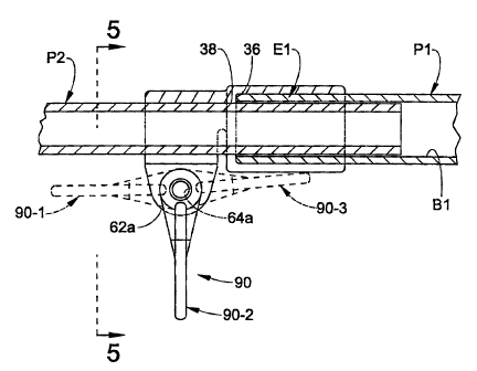
FIGURE 5 is a view taken along line 5-5 of FIGURE 4.
Detailed Description of Preferred Embodiments
Referring now to the drawings, a lever-activated lock formed in
accordance with a preferred embodiment of the present invention is shown at
10.
The lock comprises a body 20 having a base 30 and a collar 50. The body 20
is preferably defined as a one-piece molded plastic construction.
Telescoping poles are generally tubular members and, thus, the
base 30 is preferably an annular member that defines an axial through-bore 32.
The bore 32 includes a first, enlarged portion 34 that is dimensioned and
conformed for close, sliding receipt of an end portion E1 of a first pole
section
P1 therein as shown in FIGURE 4. The end E1 is preferably adhesively and/or
mechanically secured in the enlarged portion 34 of the bore 32. A radially
inwardly extending shoulder 36 is defined at the transition between the
enlarged
first portion 34 of the bore and the remaining second portion 38 of the bore
32.
The shoulder 36 provides a stop for abutment of the pole section P1
thereagainst when the end E1 of the pole section is fully inserted into the
enlarged bore portion 34 as shown in FIGURE 4. Furthermore, with the base 30
operatively secured to the pole section P1 as shown in FIGURE 4, the second
portion 38 of the bore is aligned with the bore B1 formed through the pole
section P1. The dimensions of the base 30 can vary, but one of ordinary skill
in
the art will recognize that it must have sufficient axial length to
accommodate a
sufficient length of the end E1 of the pole section P1 so that a strong
connection
between these two members is possible and so that the base 30 does not
fracture under loads encountered for the expected application of the
telescoping
pole, e.g., window washing, light bulb changing, etc.
The collar 50 of the body 20 is connected to the base 30 by a
5
CA 02436762 2003-06-27
WO 02/051562 PCT/USO1/49658
narrow neck 52 so that a substantial portion of the collar 50 is separated
from
the base 30 by a space 54. This space 54 allows for radial constriction and
expansion of the collar 50 relative to the base 30 as described below.
Referring to FIGURES 1 and 5, the collar 50 is also preferably
conformed as an annular member, but it is split so that a circumferential gap
56
is defined between first and second collar halves 60a,60b. More particularly,
each collar half 60a,60b originates at the neck 52 and terminates in an ear
62a,62b, respectively. The ears 62a,62b are arranged parallel and spaced-apart
from each other. Movement of the ears 62a,62b together causes the collar 50
to constrict radially while movement of the ears 62a,62b away from each other
causes radial enlargement of the collar 50.
The collar 50 also defines an opening or bore 70 therethrough that
is coaxial with the bore 32 defined in the base 30. The opening 70 is
dimensioned and conformed for close sliding receipt of a second pole section
P2
(FIGURE 4) therein when the collar halves 60a,60b are in a free, relaxed
position, i.e., when the collar 50 is neither constricted nor enlarged. The
collar
50 is defined to have an axial length that is sufficient to provide the collar
with
required strength and also so that the inner surface 72 defining the opening
70
contacts a sufficient axial length of the pole section P2 to grip same when
the
collar is constricted. As shown in FIGURE 4, when the second pole section P2
is slidably inserted into the collar 50, the second pole section P2 telescopes
through the base 30 and into the bore B1 of the first pole section P1.
The lock 10 includes a locking mechanism for selectively
constricting the collar 50 about the pole section P2 to prevent sliding
movement
of the pole section P2 relative to the collar. In the illustrated embodiment,
the
ears 62a,62b define respective aligned unthreaded apertures 64a,64b. A
fastener such as a screw 80 is inserted into and through theses aligned
apertures so that the screw head 82 abuts the ear 62a and so that the threaded
distal end 84 of the screw 80 projects through the ear 62b. With brief
reference
to FIGURE 3, it is most preferred that the screw 80 be conformed as shown to
6
CA 02436762 2003-06-27
WO 02/051562 PCT/USO1/49658
have a proximal portion 86 adjacent the head 82 that is purely cylindrical and
unthreaded. This proximal screw portion 86 and the aperture 64a defined in the
ear 62a are dimensioned relative to each other so that the proximal screw
portion 86 is received in the aperture 64a with a tight friction fit
sufficient to
prevent rotation of the screw 80 by means other than a tool acting on the head
82. Thus, once the screw 80 is operatively installed in the lock 10 as shown,
it
is rotationally fixed in position unless manually rotated by a user with a
screwdriver acting on the screw head 82. Both apertures 64a,64b are
unthreaded. With particular reference again to FIGURE 3, it is most preferred
that the distal end 84 of the screw 80 be threaded with a double-lead (two
threads that start at two diametrically opposed positions on the distal screw
end
84), left-handed thread for reasons that will become apparent to those of
ordinary skill in the art upon reading further.
The lock 10 comprises a control member such as a lever 90. The
lever includes a head 92 and a shank 94. The shank 94 is preferably defined as
a wide, flat tab adapted for receipt of manual force thereon. The head 92
includes a threaded aperture 96 defined therethrough. The threaded aperture
96 is adapted for coacting with the threaded distal end 84 of the fastener 80.
To
assemble the lock 10, the screw 80 is first pushed fully into the aligned
apertures
64a,64b until the screw head 82 abuts or nearly abuts the ear 62a. The screw
80 is then rotated with a tool acting on the screw head 82 to advance the head
92 of the lever 90 onto the distal end 84 of the screw until the lever 90
abuts the
ear 62b. Of course, the lever 90 can be replaced by a thumb-screw or any other
suitable control member that mates with the end 84 of fihe fastener 80 without
departing from the overall scope and intent of the present invention.
Once the lock 10 is assembled as described, the screw 80 is
frictionally fixed against further rotation owing to the friction fit of the
proximal
screw portion 86 in the aperture 64a of the ear 62a. In particular, the lever
90
is rotatably moveable on the screw 80 without causing rotation of the screw.
Of
course, other suitable means can be used to fix the screw 80 against
unintended
7
CA 02436762 2003-06-27
WO 02/051562 PCT/USO1/49658
rotation without departing from the overall scope and intent of the present
invention.
During the assembly process, the lever 90 is advanced onto the
screw 80 a sufficient amount by rotation of the screw 80 so that when assembly
is complete, movement of the lever 90 to a first (unlocked) position (shown at
90-
1 in FIGURE 4) causes the lever 90 to be retracted on the screw 80 so that the
collar halves 60a,60b move apart due to their natural resilience a sufficient
amount so that the pole P2 is able to slide freely relative to the collar 50.
Furthermore, when the lever 90 is moved from the first position 90-1 to a
second
(neutral) position 90-2, it is preferred that the pole P2 still be movable
axially and
rotationally relative to the collar 50. On the other hand, movement of the
lever
90 from the neutral position 90-2 to a third (locked) position (shown at 90-3
in
FIGURE 4) causes the lever 90 to be advanced on the screw 80 a sufficient
amount so that the lever 90 bears against the ear 62b and so that the screw
head 82 bears against the ear 62a whereby the ears 62a,62b move toward each
other a sufficient distance to constrict the collar 50 and prevent sliding
and/or
rotational movement of the pole section P2 relative to the collar 50. A user
can
use a screwdriver or like tool to rotate the screw 80 periodically to adjust
the
position of the lever 90 on the screw 80 so that the first, second and third
lever
positions are properly defined even after repetitive movement of the lever 90
between the first, second and third positions. It is most preferred that the
lever
90 abut the body 20 when moved from the neutral position 90-2 to the locked
position 90-3 to prevent over-tightening of the collar 50 about the pole
section
P2.
The preferred double-lead thread on the screw 80 provides for
maximum axial displacement of the lever 90 on the screw 80 when the lever 90
is rotated between its first, second and third operative positions. The left-
hand
thread allows for proper orientation of the lever relative to the poles P1,P2
and
proper orientation of the first and second positions. Of course, the invention
is
not to be construed as limited to use of a left-hand and/or a double-lead
screw
CA 02436762 2003-06-27
WO 02/051562 PCT/USO1/49658
The invention has been described with reference to preferred
embodiments. Modifications will occur to those of ordinary skill in the art to
which the invention pertains upon reading this specification. It is intended
that
the following claims be construed as encompassing all such modifications.
9