Note: Descriptions are shown in the official language in which they were submitted.
CA 02437086 2010-09-23
1
2
3
4
6
7 MULTIPLE PARTIAL ENCRYPTION USING RETUNING
8
9
11
12
13
14
16
17
18
19
21
22
23
24
26 COPYRIGHT NOTICE
27 A portion of the disclosure of this patent document contains material which
28 is subject to copyright protection. The copyright owner has -ho objection
to the
29 facsimile reproduction of the patent, document or the patent disclosure, as
it
-1-
CA 02437086 2003-08-12
1 appears in the Patent and Trademark Office patent file or records, but
otherwise
2 reserves all copyright rights whatsoever.
3
4 FIELD OF THE INVENTION
T his invention relates generally to the field of encryption. More
particularly,
6 in certain embodiments, this invention relates to a multiple encryption
method and
7 apparatus particularly useful -nor multiple encryption of packetized video
content
8 such as that provided by cable and satellite television systems.
9
BACKGROUND OF THE INVENTION
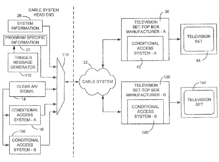
11 A conventional cable system arrangement is depicted in FIGURE 1. in such
12 a system, the cable operator processes audio/video (.A" ) content 14 with
CA
13 technology from manufacturer A (system A) using CA encryption equipment 16
14 compliant with system A at the cable system -headersd22. The encrypted Aa
content along with system information (Sl) 26 and program specific information
16 (PSI) 27 is multiplexed together and transmitted over the cable system 32
to a
17 user's Set-top box (STEM) or other receiver 36. STB 36 incorporates
decrypting CA
18 equipment from system A (manufacturer A) 40 that decrypts the A/V content.
The
19 decrypted A;V content can then be'supplied to a television set 44 for
viewing by the
user.
21 In a cable system such as that of FIGURE 1, digital program streams are
22 broken into packets for transmission. Packets for each component of a
program
23 (video, audio, auxiliary data, etc.) are tagged with, a packet identifier
or Ply. These
24 packet streams for each component of all programs carried within a channel
are
aggregated into one composite stream. Additional packets are also included to
26 provide decryption keys and other overhead information. Otherwise unused
27 bandwidth is filled with null packets.
28 Overhead information usually includes guide data describing what programs
29 are available and how to locate the associated channeis and components.
This
Docket No.: SNY-65158.01 -2- PATENT
CA 02437086 2003-08-12
I guide data is also known as system information or SI. SI may be delivered to
the
2 ST13 in-band (part of the data encoded within a channel) or out-of-band
(using a
3 special channel dedicated to the purpose). Electronically delivered Si may
be
4 partially duplicated in more traditional forms - grids published in
newspapers and
magazines.
6 Since the encryption process defined by conditional access system A is
7 proprietary to the manufacturer of the STB 36, it is difficult and expensive
for a
8 cable operator to utilize alternative sources for this hardware.
Consequently, the
9 cable or satellite operator may be locked in to a particular supplier for
hardware.
The above-referenced commonly owned patent applications address this
11 issue and therein describe inventions relating to various aspects of
methods
12 generally referred to herein as partial encryption or selective encryption.
More
13 particularly, systems are described therein wherein selected portions of a
particular
14 selection of digital content are encrypted using two (or more) encryption
techniques
while other portions of the content are left uÃnencrypted'. By properly
selecting the
16 portions to be encrypted, the content can effectively be encrypted for use
under
17 multiple decryption systems without the necessity of encryption of the
entire
18 selection of content. In some embodiments, only a few percent of data
overhead
19 is needed to effectively encrypt the content using multiple encryption
systems. This
results in a cable or satellite system being able to utilize Set-top boxes
(STB) or
21 other implementations of conditional access (CA) receivers from multiple
22 manufacturers in a single system - thus freeing the cable or satellite
company to
23 competitively shop for providers of Set-top boxes.
24 In each of these disclosures, the content is carried in the clear using a
primary Packet Identifier (P1D). A secondar}.! PIO is also assigned to the
program
26 content. Selected portions of the content are then encrypted under two (or
more)
27 encryption systems and the encrypted content transmitted using both the
primary
28 and secondary PIDs. The so-called legacy STBs operate in a normal manner
29 decrypting encrypted packets arriving under the primary PR[). The newer
STBs
operate by associating both the primary and secondary 'Pis with a single
program.
Docket No.: SNY-55158.01 -3- PATENT
CA 02437086 2003-08-12
1 Packets with a primary PID are decoded normally and packets with a secondary
2 PlO are first decrypted then decoded. The packets associated with both Pips
are
3 then assembled together to make up a single program stream.
4
BRIEF DESCRIPTION OF THE D W I G S
6 The features of the invention believed to be novel are set forth with
7 particularity in the appended claims. The invention itself however, both as
to
8 organization and method of operation, together with objects and advantages
9 thereof, may be best understood by reference to the following detailed
description
of the invention, which describes certain exemplary embodiments of the
invention,
11 taken in conjunction with the accompanying drawings in which:
12 FIGURE 1 is a block diagram of a conventional cable television sys-iem.
13 FIGURE 2 is block diagram of a dual encrypted cable television system
14 consistent with certain embodiments of the present invention.
FIGURE 3 is a flow chart of a head end encryption process consistent with
16 certain embodiments of the present invention.
17 FIGURE 4 illustrates a dual encrypted data stream consistent with
18 certain embodiments of the present invention.
19 FIGURE 5 is a high level block diagram illustrating operation of STS 136
consistent with certain embodiments of the present invention.
21 FIGURE 6 is a high level block diagram illustrating operation of STB 36
22 consistent with certain embodiments of the present invention.
.23 FIGURE 7 is a flow chart of a process for decoding and decrypting
24 content in a manner consistent with certain embodiments of the present
invention.
FIGURE 8 is a flow chart of a process for decoding and decryption of A/V
26 content in a legacy STB consistent with certain embodiments of the present
27 invention.
28
Docket No.: SNY-S5158.0e -4- PATENT
CA 02437086 2003-08-12
1 DETAILED DESK IPTIC _.F THE INVENTION
2 While this invention is susceptible of embodiment in many different forms,
3 there is shown in the drawings and will herein be described in detail
specific
4 embodiments, with the understanding that the present disclosure is to be
considered as an example of the principles of the invention and not intended
to limit
6 the invention to the specific embodiments shown and described. In the
description
7 below, like reference numerals are used to describe the same, similar or
8 corresponding parts in the several views of the drawings.
9 The terms "scramble" and "encrypt" and variations thereof are used
synonymously herein. Also, the term "television program" and similar terms can
11 be interpreted in the normal conversational sense, as well as a meaning
wherein
12 the term means any segment of e content that can be displayed on a
television
13 set or similar monitor device. The term "video" is often used herein to
embrace not
14 only true visual information, but also in the conversational sense (e.g.,
"video tape
recorder") to embrace not only video signals but associated audio and data.
The
16 term "legacy" as used herein refers to existing technology used for
existing cable
17 and satellite systems. The exemplary embodiments disclosed herein are
decoded
18 by a television Set-Top Box ( T ), but it is contemplated That such
technology will
19 soon be incorporated within television receivers of all types whether
housed in a
separate enclosure alone or in conjunction with recording and/or playback
21 equipment or within a television set itself. The present, document
generally uses
22 the example of a "dual partial encryption" embodiment, but those skilled in
the art
23 will recognize that the present invention can be utilized to realize
multiple partial
24 encryption without departing from the invention. Partial encryption and
selective
encryption are used synonymously herein.
26 Turning now to FIGURE 2, a cable television system suitable for use in
27 practicing a dual encryption embodiment of the present invention is
illustrated.
28 Those skilled in the art will appreciate that the present invention could
also be
29 implemented using more than two encryptions systems without departing from
the
Docket No.: SNY-55158.01 - - PATENT
CA 02437086 2003-08-12
1 present invention. The illustrated head end 100 implements the dual partial
2 encryption scenario of the present invention by implementing a retuning to a
3 different channel to accommodate decryption of an encrypted portion of a
partially
4 encrypted selection of content.
6 Head end 100 receives scrambled content from one or more suppliers, for
6' example, using a satellite dish antenna that feeds a satellite receiver
(not shown).
7 The satellite receiver operates to demodulate and descraimble the incoming
content
8 and supplies the content as a stream of clear (unencrypted) data. It is
assumed,
9 for purposes of the present embodiment of the invention, that the data from
the
satellite receiver is supplied as NIPEG (Moving Pictures Expert Group)
compliant
11. packetized data. This unencrypted (clear) digital television signal 14 is
selectively
12 applied to a first conditional access encryption system A 18 as well as to
a second
13 conditional access encryption system B 104. Encryption system 18 can be the
14 legacy encryption system used in the conventional single encryption system
of
FIGURE 1. Encryption system 104 can be a new encryption system that is to be
16 added to the cable (or equivalently satellite) television system. The clear
AN signal
17 14 is also applied to a multip exec 110 for selective transmission over the
cable
18 system as will be described shortly. Encrypted portions of the clear signal
14 as
19 produced by encryption systems 18 and 104 are also selectively applied to
multiplexer 110 in accordance with the present invention as will be described.
In
21 addition to these signals, system information 26 and program specific
information
22. 27 is applied to multiplexer 110.
23 In accordance with the operation of certain embodiments consistent with the
24 present invention, selected segments of the content are encrypted under
both
encryption systems 18 and 104. In accordance with any suitable algorithm,
26 segments of the clear content are selected for encryption. Any given
selected
27 segment that is to be dual encrypted is duplicated and encrypted by both
systems
28 18 and 104. These selected segments are then inserted at Multiplexer 110
into the
29 outbound data stream in place of the corresponding original, unencrypted
content.
These selected encrypted segments are inserted as content in the same channel
Docket No.: >NY-S5158.01 -6- PATENT
CA 02437086 2003-08-12
1 as the unencrypted content (channel A) as well as in a second channel
(channel
2 B).
3 When a segment is selected for encryption, a trigger message is generated
4 (e.g., as a user data message in the Program Specific i form tion (PSI' O,
by a
trigger message generator 116 and transmitted in advance of the encrypted
6 content. This trigger message is used by a Set-top box 136 as a signal that
a
7 portion of the upcoming content will be encrypted and will appear on a
second
8 channel. Thus, when the ST 136 receives this message it prepares to retune
to
9 the second channel (channel B) at a time or packet number prescribed by the
trigger message. Thus, at the prescribed time, STB 13(retunes to channel B and
11 uses a decryptor for conditional access system 140 to decrypt the inc )ming
12 encrypted segment. In this manner, STB 1 36 need not comply with the conc:_-
%onal
13 access system A 40 of ST3 36 and can thus be supplied by a different
14 manufacturer (avoiding need for a license to conditional access system A).
The
unencrypted and decrypted AN signal is then passed to television set 144,
16 At the legacy STS 36 using conditional access system A 40, a mixture of
1 ? encrypted and unencrypted packets are received. Conditional access system
A
1 decrypter 40 on such systems automatically decrypt that which is encrypted
and
1 pass that which is not. Thus, STB 36 operates normally with the dual
encryption
operating transparently.
2 i The operation of the cable system head end I D0 in generating the dual
22 partially encrypted data stream can be described by the process 200 of
23 FIGURE 3 starting at 204. tnencrypted content is seat out on channel A of
the
24 head end 100 to the cable system 32 at 208. If the and of the content is
not
reached at 212, a trigger message is sent to the cable network 32 at 216. This
26 trigger message defines a starting time or packet number (and possibly a
stopping
27 time or packet number) for encrypted content to begin and further specifies
the
28 channel that the next segment of encrypted content will use. The selected
segment
29 of content is then dual encrypted (in this exarnole, but multiply encrypted
in general)
and transmitted using encryption method A and channel A at 220 and using
Docket No.: Si`d`(-55155.01 -7- PATENT
CA 02437086 2003-08-12
1 encryption method B and channel B at 224. If the end of the content is not
reached
2 at 230, another trigger message (according to the current embodiment in
which a
3 stop time or packet number is not defined for the encrypted segment at 216)
is
4 generated at 236 indicating that clear content is to follow at a prescribed
start time
or packet number over channel A. When the end of the content is reached at 212
6 or 230, the process stops at 240.
7 In accordance with one embodiment consistent with the present invention,
8 the ; content can be segmented such that several seconds, e.g., ten seconds,
9 of content is encrypted periodically to encrypt, for example, between 10 and
35
percent of the AN content. This, however, should not be considered limiting
since
11 any desired segmentation can be used to produce segments of encrypted
content.
12 In preferred embodiments, encrypted segments last between several seconds
and
13 several tens of seconds, but this should not be considered limiting. Due to
the
14 nature of MPEG encoding, encryption of certain data such as I Frames and P
Frames, or any packet containing intra-coded data, will result in a further
16 scrambling effect on the picture beyond the encrypted segment for any
hacker
17 attempting to view the A/V content without authorization. Thus, as the
STB's
18 MPEG decoder attempts to recover from loss of data following a segment of
19 encryption, there may be several seconds or longer of content that the
decoder
cannot reconstruct until the next frame or packet of intra-coded data is
received.
21 This results in a greater encryption effect than simply loss of the
encrypted
22 segments of content.
23 The head end 100, thus, produces a stream of NV data that may resemble
24 data stream 250 shown in FIGURE 4. The data stream 250 may start with
either
a clear or encrypted data stream without limitation. A segment of clear data
26 254 in the data stream is followed by a trigger message 256 specifying the
channel
27 and timing of an encrypted segment to follow. Encrypted segments 262 and
266
28 follow in any order (but generally intermingled) with encrypted content on
29 channels A and B using encryption methods A and 8 as previously described.
A
trigger message 270 indicates that unencrypted content will follow at a
specified
Docket No.: SNY-S5158.0i - 3- PATENT
CA 02437086 2003-08-12
I timing on channel A. This is followed by a segment 2714 of clear content on
2 channel A until such time as a next segment is to be encrypted. The next
segment
3 of encrypted content is then s`gnaled by trigger message 280 and so on,
4 Upon receipt of a data stream such as stream 250, STB 136 operates as
illustrated in the block diagram of FIGURE S. The multiplexed AN data stream
6 from multiplexer 110 which is generally quadrature amplitude modulated (QAM)
is
7 received at a tuner/demodulator 302 that tunes to the appropriate carrier
frequency
8 and demodulates the QAM signal into a strew of packets. This stream of
packets
9 is delivered to a demultiplexer 306 that selects appropriate: packets for
further
processing (Note that the strearn of packets may include multiple channels and
11 multiple programs as well as other data packets.) . When, the demuitiplexer
detects
12 a trigger message (which may be a part of the Program Specific Information
13 encoded as user private data, this packet is delivered to a control
processor that
14 incorporates a trigger message decoder 310 in one ernooodirnent. In other
embodiments, the, trigger message decoder may be implemented in any other
16 suitable manner.
17 The trigger message decoder 31 0 decodes the trigger message to determine
18 when the change between encrypted and unencrypted content will occur and
what
channel will bear each. The) trigger message decoder 310 then instructs the
demultiplexer 306 to tune to a specified Packet identifier (PI1)), and if
necessary,
21 to tune the tuner/demodulator 302 to a different frequency channel at the
22 appropriate time to receive and decode the next segment of content.
23 The content is delivered to decrypter 140 Which passes unencrypted packets
24 unaltered and decrypts the encrypted packets when they are encountered. The
content is then passed to an A/V decoder 316 that decodes the content into
26 decoded A/V data (in either analog or digital form as, desired) to the
television
27 receiver 144.
28 The operation of legacy STB 36 is depicted in the block diagram of FIGS
29 6. Tuner/demodulator 330 operates on the multiplexed data stream in a
manner
Docket No.: SNY-S5158, O1 -9- PATENT
CA 02437086 2003-08-12
I similar to that of 302 to tune and demodulate the incoming signal. This
signal is
2 then dermultiplexed at demultiplexer 334 to select the appropriate channel
(channel
3 A). This demultiplexed output is then passed to decrypter 40 which decrypts
4 encrypted packets and passes unencrypted packets undisturbed to the
decoder 340. AN decoder 34=:0 operates in a manner similar to that of A/V
decoder
6 316 to produce decoded AN output.
7 Turning now to FIGU 7, a process 350 rsor decoding a data stream at. STS
6 136 consistent with certain embodiments of the invention is depicted in flow
chart
9 form starting at 354. At 358 the STB tunes to channel A (which may involve a
tuning process in the STB's tuner as well as selection of a particular set of
audio
1111, and video PIDs) associated with a particular program. .jnencrypted
content is then
12 received at 362 using channel A in the illustrated embodiment (but
encrypted
13 content could equally well be received first). If the end the content is
not reached
14 at 366,* a trigger message can be received at 370 signaling a switch to a
new
channel B to receive a segment of encrypted content at a prescribed time or
packet
16 number. At an appropriate time, the ST 1 36 'then tunes to channel B at 374
to
17 begin receiving and decrypting the content on channel 3 at 378. if the and
of the
18 content is not received at 332, another trigger message may be received to
signal
19 a switch to unencrypted content on channel A (or another channel such as
channel
C) at 386. Control then returns to 358 where the STS 136 tunes to the new
channel
21 to receive unencrypted content at the prescribed time. When the and of the
content
22 is received at either 366 or 382, control passes to 380 where the process
stops.
23 Operation of a legacy STB such as 36 is depicted by process 400 of FIGURE
24 8 starting at 402. At 406, the STS 36 tunes to channel A to receive a
selected
program and begins receiving content over channel A at 410. Any trigger
26 messages received are ignored at S T 8 36. If the content is encrypted at
414,
27 control passes to 418 where. the content is decrypted. If the content is
not.
28 encrypted at 414, the data are passed without alteration at 414 by the
decrypter.
29 When the end of the content is reached at 422, the process stops at 428.
Docket No.: SNY-S5158.O1 -10- PATENT
CA 02437086 2003-08-12
1 While the process 400 depicted in connection with operation of legacy S T B
2 36 is the normally contemplated process, it is also possible to direct
trigger
3 messages to the legacy S T 8 36 to cause a channel change for encrypted or
4 unencrypted content, rendering the content more difficult for a hacker to
obtain
without authorization. Similarly, channel changes for the encrypted and
6 unencrypted content can be made to make reception by a hacker more difficult
is
7 _ contemplated in connection withthe operation of STB 135. Also, in a
variation of
8 the present invention a return to the primary (i.e., unencrypted) channel
could be
accomplished by use of a timer such that the trigger signal that signals a
channel
I change from the first segment to the second segment can incorporate a
duration
1 I field that determines when a change back to the primary channel is to
occur. Other
12 variations will occur to those skilled in the art upon consideration of the
present
13 disclosure.
14 Those skilled in the art will recognize that the present invention has been
. described in terms of exemplary embodiments based upon use of a programmed
is processor. However, the invention should not be so limited, since the
present
17 invention could be implemented using hardware component equivalents such as
18 special purpose hardware and/or dedicated processors which are equivalents
to
19 the invention as described and claimed. Similarly, general purpose
computers,
microprocessor based comp~.uytyers, micro-controllers, optical
computtgers,p~anallog
21 co 8n~:. ute , dedicated pr oceesesors a r?d or dedi atedd, haa.I ¾1~j
V~OFir ei`d logic G 1 ECa+@1 be used
22 to construct alternative equivalent embodiments of the present invention.
23 Those skilled in the artwill appreciate that the program steps and
associated
24 data used to implement the embodiments described above can be implemented
using disc storage as well as other forms of storage such as for example Read
26 Only Memory (RO 1) devices, Random Access Memory (RAM) devices; optical
27 storage elements, magnetic storage elements, magneto-optical storage
elements,
28 flash memory, core memory and/or other equivalent storage technologies
without
29 departing from the present Invention. Such alternative storage devices
should be
3 considered equivalents.
Docket No.: SNY-S5158.01 -1 1-- PATENT
CA 02437086 2003-08-12
I The present invention, as described in embodiments herein, is implemented
2 using a programmed processor executing programming instructions that are
3 broadly described above form that can be stored on any suitable electronic
storage
4 medium or transmitted over any suitable electronic communication medium or
otherwise be present in any computer readabie or propagation medium. However,
6 those skilled in the art will appreciate that the processes described above
can be
implemented in any number of variations and in many suitable programming
8 languages without departing from the present invention. For example, the
order of
9 certain operations carried out can often be varied, additional operations
can be
added or operations can be deleted withou departing from the invention. Error
11 trapping can be added and/or enhanced and variations can be made in user
12 interface and information presentation without departing from the present
invention.
13 Such variations are contemplated and considered equivalent.
14 Software code and/or data embodying certain aspects of the present
invention may be present in any computer readable medium, transmission
16 medium, storage medium or propagation medium including, but not limited to,
17 electronic storage . devices such as those described above, as well as
carrier
18 waves, electronic signals, data structures (e.g., trees, linked lists,
tables, packets,
19 frames, etc.) optical signals, propagated signals, broadcast signals, trans
ission
media (e.g., circuit connection, cable, twisted pair, fiber optic cables,
waveguides,
21 antennas, etc.) and other media that stores, carries or passes the code
and/or data.
22 Such media may either store the software code and/or data or serve to
transport
23 the code and/or data from one location to another. in the present exemplary
24 embodiments, IMPEL compliant packets, slices, tables and other data
structures
are used, but this should not be considered limiting since other data
structures can
26 similarly be used without departing from the present invention.
27 While the invention has been described in conjunction with specific
28 embodiments, it is evident that many alternatives, modifications,
permutations and
29 variations will become apparent to those skilled in the art in light of the
foregoing
description. Accordingly, it is intended that the present invention embrace al
such
Docket No.: SNY-55158.01 -12- PATENT
CA 02437086 2003-08-12
s alternatives, modifications and variations as faH within the scope of the
appended
2 chairs.
3
4
Docket No.: SNP"-S5I58.01 -13- PATENT