Note: Descriptions are shown in the official language in which they were submitted.
CA 02437301 2010-09-02
- 1 -
METHOD FOR MONITORING THE REGISTRATION OF ROAD TOLLS
The invention relates to a method for monitoring the
registration of road tolls with a monitoring system.
US 5,757,286 describes such a monitoring system. The
monitoring system is fixed and registers vehicle
information via registration devices and assigns the
vehicle information to the time of monitoring.
WO 99/66455 describes such a monitoring system. It is
used for fixed, automatic monitoring in WO 99/66455. A
vehicle device installed in a vehicle carries out the
registration of tolls autonomously on board the vehicle.
The satisfactory payment of the tolls is monitored by the
road-side fixed monitoring system. For this purpose the
monitoring system communicates with the vehicle device by
means of communication devices. The passing vehicle is
assigned to a specific vehicle class with the aid of
sensors which serve as registration devices for optical
and acoustic measured values. The monitoring system has
a registration device for optically registering the
number plate of the passing vehicle.
The object of the invention is to provide a monitoring
method which improves the present monitoring system to
the effect that each vehicle on each road section can be
monitored by registering usable vehicle information.
In accordance with one aspect of the present invention
there is provided a monitoring method for registration
of road tolls with a monitoring system having a
plurality of different types of registration devices
arranged at different locations for registering
CA 02437301 2010-09-02
- la -
differing kinds of vehicle information, said method
comprising: activating, by way of a trigger device,
each of the registration devices independently of one
another at respective registration times at which a
spatial position of the vehicle relative to a
respective registration device for each particular
type of device is at an optimum; registering various
vehicle information items, separately in spatial and
chronological terms, by way of the registration
devices; assigning, by way of said monitoring system,
said vehicle information items to a reference time by
transforming said vehicle information items relating
to respective registration times into vehicle
information relating to a corresponding reference
time, based on vehicle speed; and associating said
vehicle information with a particular vehicle, based
on said reference time.
In accordance with another aspect of the present
invention there is provided a monitoring method for
registration of road tolls with a monitoring system
having fixed monitoring systems provided for automatic
monitoring and transportable monitoring systems
provided for mobile monitoring, with a plurality of
different types of registration devices arranged at
different locations for registering differing kinds of
vehicle information, said method comprising:
activating, by way of a trigger device, each of the
registration devices independently of one another at
CA 02437301 2010-09-02
- lb -
respective registration times at which a spatial
position of a vehicle relative to a respective
registration device is at an optimum for each
particular type of device; registering various
vehicle information items, separately in spatial and
chronological terms, by way of the registration
devices; and assigning, by way of said monitoring
system, said vehicle information items to the vehicle
and to a reference time based, at least in part, on
vehicle speed; and using a combination of said fixed
and transportable monitoring systems for stationary
monitoring, with an operating mode of the automatic
monitoring station being switchable to stationary
monitoring.
The monitoring method achieves a good quality level of
the registered vehicle information by virtue of the
fact that the vehicle information which is to be
registered is registered by the individual registration
CA 02437301 2003-07-31
p036247/WO/l
devices when the spatial arrangement between the
vehicle and the registration device is at an optimum.
This is the case, for example, with a camera for
recognizing registration numbers when the camera is
placed obliquely in front of the vehicle. For infrared
communication, for example, a line-of-sight connection
is necessary between the registration device and the
infrared communication device in the vehicle.
The vehicle information which is registered in the
monitoring system is registered separately in spatial
and chronological terms and vehicle information which
is associated with a vehicle is assigned to this
vehicle. The vehicle information which has been
registered by a monitoring system is assigned to a
reference time. The reference time can be a single
time, for example the time of the first or the last
registration, the mean between the first and last
registration times or the time at which the vehicle is
located spatially in the center of the registration
area of the monitoring system. When necessary, a
plurality of reference points, to which the values are
then assigned, can also be selected. Assignment makes
it possible to define which vehicle information is
associated with which vehicle, and to assign whei-, the
vehicle has passed the monitoring system, the vehicle
speed being used to compensate for the difference
between the registration time and the reference time.
To do this, vehicle information at the registration
time is transformed into vehicle information at the
reference time- This facilitates the use of vehicle
information in other methods and permits the
registration devices to be mounted in a spatially
concentrated fashion in order to avoid a spatially
extended arrangement.
The monitoring method is distinguished by the fact that
the monitoring system may be embodiedl so as to be fixed
CA 02437301 2003-07-31
P036247/WO/l
3 -
or transportable. All three parts of the monitoring
system basically register the same vehicle information,
but can be used in different ways.
A fixed monitoring system permits automatic monitoring
operation without the use of additional personnel. The
fixed monitoring system provides advantages in carrying
out a preselection as part of a stationary monitoring
process as it registers the vehicle information of all
the passing vehicles without additional expenditure.
When stationary monitoring is carried out, the
transportable monitoring system is used in conjunction
with the fixed monitoring system. Mobile monitoring is
based on the transportable monitoring system. The
flexible use of fixed and transportable monitoring
systems therefore results in a monitoring concept
composed of automatic monitoring, mobile monitoring and
stationary monitoring.
This makes it possible to monitor each vehicle on each
freeway section and to keep the use of the monitoring
systems flexible according to various criteria, for
example the highest possible detection rate of people
making incorrect payments and people who are failing to
pay, the smallest possible deployment of personnel, the
smallest possible number of incorrect detections, the
smallest possible expenditure on collecting fines and
the acquisition of evidence which will as far as
possible stand up in court.
The registration devices can be activated automatically
or manually. For automatic monitoring 200.1, the
triggering of the registration devices takes place
automatically, permitting this monitoring system to be
operated without the direct deployment of personnel.
The registered v,:-! hic..1e information comprises
information on the movement, in particular lane
CA 02437301 2003-07-31
P036247/WO/1
4 -
changes, acceleration, braking operations and the speed
of the vehicle. This permits the vehicle information
which is not regi:,tered simultaneously within a
monitoring system to be assigned to a vehicle and to a
reference time.
The detection of number plates is advantageous, for
example if the monitoring system cannot communicate
with the vehicle, for example because said vehicle does
not have a vehicle device, by virtue of the fact that
it then registers only the number plate and compares it
with the content of databases in order to determine
there, for example, whether there is a valid driving
authorization for the detected vehicle class and for
this time-
Preferred exemplary embodiments of the invention are
described below with reference to the associated
drawings, in which, in each case in a schematic view,
Figure 1 shows a blec:k circuit diagram of a monitoring
system with external interfaces,
Figure 2 shows a block circuit diagram of the
monitoring system with internal interfaces,
Figure 3 shows a diagram of the first part of a
monitoring sequence,
Figure 4 shows a diagram of the second part of a
monitoring sequence,
Figure 5 shows the geometric arrangement of the
sensors of the monitoring system,
Figure 6 shows a plan view of the measurement areas of
the monitoring system on the road,
T--
CA 02437301 2003-07-31
P036247/WO/1.
- 5 -
Figure 7 shows the internal interfaces and data flows
in the monitoring system,
Figure 8 shows the arrangement of an automatic and
stationary monitoring facility on a section
of freeway.
in the following description, toll is to be understood
as fees which have to be paid for the use of a road.
The objective of the monitoring is to ensure that the
obligation to pay a toll is enforced to a high degree,
while treating all persons obliged to pay a toll
equally, by registering persons who do not pay and
persons who pay the incorrect amount, by collecting at
a later time tolls which have not been paid and by
imposing fines.
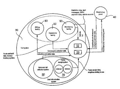
The integration of the monitoring system 10 with
monitoring control center 20 into the toll system 30 is
illustrated in Figure 1. The monitoring system 10
receives road data and tariff data from the operations
facility 50 in order to be able to determine how high
the toll is for the vehicles to be monitored. Key
updates are used for transmitting data in a protected
fashion. The data relating to the toll paid in the dual
toll-collection system is transmitted from the
subsystems of said dual toll-collection system to the
monitoring system 10. The contents which are determined
during the monitoring process are transferred to
relevant locations for processing and then passed on
via the monitoring system 10 to the billing facility 80
for subsequent collection.
There are the following forms of monitoring: automatic
monitoring 200.1,
stationary monitoring with automatic preselection,
mobile monitoring and operational monitoring.
CA 02437301 2003-07-31
P036247/WO/l
- 6 -
The automatic monitoring processes check the
satisfactory payment of tolls in a fixed fashion at
fixedly defined locations in the road network for which
tolls are to be paid, without the assistance of
monitoring personnel and without stopping the vehicles
(50.1., 50.2.). In what follows, a monitoring system
10, which is used for automatic monitoring, is meant by
the term "automatic monitoring system". 150 of the 300
automatic monitoring processes are additionally
performed by the automatic preselection for a
stationary monitoring process- Here, vehicles which are
indicated by the automatic preselection are led off by
personnel from the monitoring point 40 and monitored in
the stopped state.
For mobile monitoring, monitoring vehicles move along
interspersed in the flowing traffic and extract
vehicles (50.1., 50.2.) for which monitoring is
necessary from the traffic at suitable stopping points
in order to monitor whether the stopped vehicle has
complied with the obligation to pay a toll, and if
necessary initiate sanctions. Below, "mobile monitoring
systems" mean transportable monitoring systems which
are used for mobile monitoring.
In contrast to the other forms of monitoring, the
operational monitoring does not check the vehicles
(50.1., 50.2.) directly while the freeway is being used
but rather monitors operational procedures and vehicles
(50.1., 50.2.) subsequently to determine whether routes
for which a toll is due have been used.
The combination of these forms of monitoring and the
configuration provided for them ensures that each
vehicle on each section of freeway can be monitored.
Irrespective of the form of monitoring, the monitoring
process is composed of the following basic functions:
CA 02437301 2003-07-31
P036247/WO/l
- 7 -
determination of the contents of the use of a road for
which a toll is due by a vehicle which is liable to pay
a toll, determination of the contents by checking the
payment of the toll either directly on the vehicle
device, in the database of the central system or by
checking automatically recorded evidence, subsequent
collection of the toll when an infringement is
determined, implementation of proceedings for
collecting a fine, if necessary enforcement of notices
for subsequent collection of tolls and the imposition
of fines. The monitoring processes register all the
vehicles (50.1., 50.2.) which are liable to pay tolls
irrespective of the form of monitoring and the selected
toll-collection system and monitor in particular if no
toll at all has been paid.
This is ensured by virtue of the fact that all the
monitoring systems 10 receive data on the vehicle
(50.1., 50.2.) which is to be monitored and on
associated receipts of funds - specifically both from
the vehicle devices used in the automatic toll-
collection system 60 and from the fund receipt database
of the fund receipt systems 70.
The structural and technical devices of the monitoring
system 10 are summarized in the following table and
explained in brief:
Com onent Description
Central _
Monitoring The monitoring center 20 of the toll
center 20 syst~2m 30 and is equipped with all
the necessary computers, peripherals,
communication paths, personnel and
other resources.
Workstations for PC-supported workstations in the
classifying, monitoring center 20.
identifying and
determining
contents
CA 02437301 2003-07-31
P036247/WO/1
S -
Component Description
Workstations for PC-supported worksl:ations in the
generating monitoring point 40 which have access
orders for the to the evidence data of the
imposition of monitoring center 20 via a fixed
fines link.
Automatic fixed
monitoring
Automatic Fixed, fully automatic monitoring
monitoring 200.1 systems which detect vehicles in all
lanes including the hard shoulder,
classify them and check them for
correct payment of tolJ.s.
They communicate with the monitoring
center 20 and the vehicle devices of
passing vehicles. The transmission is
protected cryptographically.
Special, defined monitoring systems
can perform the function of automatic
preselection for stationary
monitoring.
Stationary
monitoring
Switch cabinet Fixed device for the wire-free
connection of the leading-off aids to
the monitoring station 200.3.
Dependent on the local conditions,
mast for holding the antenna for
communication with the automatic
monitoring system.
Leading-off aids Transportable devices which can
represent an image, the detected
registration number and the result of
the determination of the contents by
the preceding automatic monitoring
200-L.
Monitoring Data radio-enabled, transportable
system for computers for supporting the
stationary determination of the contents for
monitoring vehicles which are led off to a
(transportable monitoring station 200.3.
monitoring They have a GSM interface for calling
system) current funds receipt data for a
specific vehicle registration number
in the monitoring center 20 and the
possibility of interrogating data
from the vehicle device via DSRC or a
cable link.
CA 02437301 2003-07-31
1?036247/WO/l
- 9 -
component Description
Mobile
monitoring
Mobile Supports mobile monitoring while
monitoring traveling and after the truck has
system been led off.
(transportable The monitoring systems are equipped
monitoring with an autonomous section-detection
system) module for detecting and representing
the aection which is being traveled
on al: a particular time and are
connected to a GPS antenna in the
vehicle. The data of the vehicle
device of a monitored truck is
interrogated via a DSRC transceiver
component. The communication with the
monitoring center 20 is carried out
via a suitable communications
interface (GSM/GPRS).
The interfaces and data flows of the monitoring system
which are external from the point of view of the
monitoring system 10 are represented in Figure 1.
5
The monitoring system 10 receives collection data from
the automatic toll-collection system by reading out
from the vehicle devices during a monitoring process.
10 The monitoring system 10 receives funds receipt data
from the fund receipt system. It carries out monitoring
in conjunction with the route data and tariff data from
the operations facility 50 and supplies subsequent
collection data to the billing facility 80 in the case
of infringements of the obligation to pay a toll. The
billing facility 80 processes the subsequent collection
data in a way which is analogous to that for the funds
data which it has received via the dual toll-collection
system-
Figure 2 shows the monitoring-internal data flows
between the monitoring center 20 and monitoring systems
10 in detail. The forms of monitoring are: automatic
CA 02437301 2003-07-31
P036247/WQ/1
i0 -
monitoring 200.1, sLaticnary monitoring and mobile
monitoring.
The automatic monitoring 200.1, with the associated
subsequent processing, subsequent collection and
treatment of the infringements of rules by the
monitoring point 40, takes place in the monitoring
center 20.
Inter alia, automatic monitoring processes 200.1 are
used for determining the contents, are installed on
bridges and carry out the monitoring of all the passing
vehicles (50.1., 50.2.) in the following steps:
detection of vehicles, step 301, classification of
vehicles, step 311, recording and determination of the
motor vehicle registration number, step 309, DSRC
communication with the vehicle device (DSRC: Dedicated
Short-Range Communication), step 317, decision process
and, if appropriate, storage of evidence, steps 318 to
331.
The monitored points are equipped with monitoring
systems 10 in such a way that all the lanes of the
monitoring cross section including the hard shoulder
are registered and monitored. In the process, changes
of lanes as far as the direct vicinity of the
monitoring cross section are registered in order to be
able to assign all the registered data reliably to the
correct vehicle image even under difficult traffic
conditions (congestion) . The action diagram in Figure 3
and Figure 4 shows the provided sequence of an
automatic monitoring process. Using special sensors it
is possible for vehicles (50.1., 50.2.) which are due
to pay tolls to be detected with a high degree of
reliability and for their path to be pursued, step 301.
This takes place irrespective of whether 'there is an
obligation to pay a toll, whether the toll has been
paid at all and what method of payment has been used to
CA 02437301 2003-07-31
P036247/WO/l
- 11 -
do so. The sensors are capable of detecting vehicles
which are obviously not liable to pay a toll, such as
passenger cars and motorbikes as such, and of avoiding
taking a picture of these vehicles.
As soon as a vehicle which has been detected as
possibly liable to pay a toll has approached the
monitoring bridge to a distance of approximately 10 to
12 m, a digital overview, in steps 305 and 306, and a
plurality of digital registration number images - in
order to cover the entire range of the lanes - step
304, are recorded. These are used to identify the
vehicle and can be used later as proof. The number
plate is searched for in the image, the country of
origin is determined and the motor vehicle number
evaluated, step 309. For this purpose, an OCR (OCR:
Optical Character Recognition = automatic
identification of characters) method is implemented for
reading the registration number. The monitoring system
10 determines the country of origin as far as possible
from the letter/number combination. If this is not
sufficient, separation characters and the character
font are used for the classification of nationalities.
Reliable recognition of the country of origin is not
necessary for fault-free decision for a particular
case.
in parallel with this, DSRC communication is used to
check whether the vehicle is equipped with a vehicle
device, and feeds information back to the vehicle
device, step 317. 1E there is -no response by the
vehicle device during the DSRC communication or it
signals a fault, it assumes that the vehicle is
participating in the funds receipt system, branch "no"
of step 319. The registration number which is
determined is then reconciled with a so-called white
list which contains all the funds receipt operations
which have been performed for this time and for this
CA 02437301 2003-07-31
P036247/W0/l ~
- 12 -
monitored section. The white list is present in a
database in the monitoring center 20. Access takes
place via a fixed line--bound data communication link.
When the vehicle passes the monitoring bridge, it is
classified using a measurement, step 311, insofar as
this is possible owing to measurable parameters.
If there are doubts, arising from the preceding steps,
about the declared toll class, the motor vehicle
registration number'or whether the obligation to pay a
toll has been fulfilled correctly, the automatic
recording and protection of proof items takes place in
all cases, step 329.
Optionally, the automatic monitoring system 10 makes
available all the information - via an interface which
can be activated - for subsequent stationary monitoring
which is required to select the vehicles (50.1., 50.2.)
which are to be led off-
In order to determine the toll class and level of
tolls, in the course of the determination of facts,
each vehicle which passes the monitoring cross section
is detected automatically and it is determined as far
as possible whether it is liable to pay a toll or not,
steps 311, 314, 315.
For the classification of a vehicle, various
measurement data are determined as it passes through
the monitored area, steps 304, 305, 306- Its assignment
to a weight class is based on the physical number of
axles, the width of the driver's cab, the height of the
driver's cab, the overall height and the overall width.
In order to be able to assign vehicles (50.1., 50.2-)
between 7.5t and 18t to a permitted overall weight more
accurately, there is provision for possible brand
CA 02437301 2003-07-31
P036247/WO/l
- 13 -
symbols of manufacturing firms to be determined
optoelectronically. The assignment can then be carried
out using specific dal:a on the model series of these
companies, step 310.
Furthermore, during the classification in step 311, the
vertical profile of the vehicle determined in step 306
is evaluated in order to be able to distinguish trucks
from buses and to recognize trucks with and without
trailers. Trailered couplings which are present can be
clearly discerned on the profiles which are recorded.
Individual vehicles (i0.1., 50.2.) can be freed from
the obligation to collect a toll even if they fulfill
the physical conditions for said obligation. This is
determined - after the determination of the motor
vehicle registration number - online by reference to a
list which is stored in the monitoring center 20 and
which contains all the, registration numbers of trucks
which are not liable to pay a toll, step 319. The list
also contains registration numbers of vehicles which
have already been detected in the manual subsequent
processing as not liable to pay a toll or registered as
such. If there is an interface with the Federal Motor
Vehicle Authority available, the enquiry for German
vehicles (50.1., 50.2.) is made via a list called up
from there.
After the toll class has been detected, the level of
toll for the section t=raveled on can be determined by
reference to the calculation parameters and formulas
stored in the monitoring system 10 and compared with
the toll actually paid. If the question of obligation
to pay a toll cannot be clarified unambiguously on the
basis of the external features and if the monitoring
center 20 does not have a corresponding classification
entry, an infringement is hypothetically assumed, step
313 or 329, a proof data record is assembled and it is
CA 02437301 2003-07-31
P036247/WO/l
- 14 -
then presented to the monitoring center 20 for further
manual clarification.
A reliable distinction between vehicles liable to pay
tolls and vehicles which are not liable to pay tolls is
thus ensured with the exception of dubious cases which
can be clarified only through manual post-processing.
Their number will be kept as small as possible by the
automatic monitoring system 10 using its technical
equipment and the detection of the manufacturer- in
order to arrive at a decision in a particular case, the
monitoring system 10 automatically carries out a pre-
decision as to whether the holder or, the driver of a
vehicle is someone who pays up correctly or someone who
3.5 avoids paying a toll- The latter also includes holders
or drivers of incorrectly declared vehicles. in order
to check this, it is necessary to evaluate the DSRC
communication, the ve:hicle`s own classification data
and the classification information of the monitoring
center 20 and of the motor vehicle registration number
which is determined.
Whether or not a vehicle participates in the automatic
toll-collection system can be clarified by means of the
attempt of the monitoring system 10 to establish a DSRC
communication with a vehicle device which is possibly
present, step 317.
If a vehicle device responds correctly, it signals its
operational capability, step 318, branch "yes". If the
toll-related data from the acknowledgement - such as
motor vehicle registration number, toll class and level
of toll, step 320 - correspond to the data of the
automatic classification and determination of the
registration number, step 322, the vehicle is
classified as that of a person who pays up correctly
(branch "yes" from step 322). The recorded image data
is cleared if there is no suspicion of tampering and
CA 02437301 2003-07-31
P036247/WO/l
the vehicle device or the collection card are not on a
blocked list (step 323) . If there is no response from
the vehicle device or if it signals a fault during the
DSRC communication, it is assumed that the vehicle is
-participating in the funds receipt system (branch "no"
of step .318). The registration number which is
determined optoelectronically is then reconciled with
the white list in the monitoring center 20, said white
list containing all the valid funds receipt operations
for the section which is to be monitored and the
monitoring time (step 319, decision in step 321).
In this way, persons who pay correctly are also
detected and are not considered further. The data from
persons who pay correctly are, however, stored in the
monitoring system 10 until the expiry of the validity
of the use authorization in order to be able to prove
its possible multiple use. In this way it is also
possible to reliably rule out a situation in which
incorrect decisions occur owing to doubles - i.e.
vehicles with. the same registration number from
different countries of origin. This is because in this
case it is possible, by means of manual post-
processing, to determine which user is the person
avoiding the payment of tolls.
The data on unambiguously detected incorrect payers and
non-payers which is necessary to provide proof is
registered, stored in a cryptographically protected
form and passed on to the monitoring center 20- If the
situation cannot be determined unambiguously by the
monitoring system 1.0 because, for example, the
registration number of a vehicle without a vehicle
device could not be read automatically, the data which
is necessary for the decision is passed on in the same
way to the monitoring center 20.
CA 02437301 2003-07-31
P036247/WO/l
- .l6 -
If it is not possible to detect unambiguously an
obligation to pay a toll in the case of a vehicle
without a vehicle device, all the data which is
necessary for providing proof is also, passed on to the
monitoring center 20 for clarification. In another
procedure, a large number of vehicles (50.1-, 50.2.)
which are liable to pay toils and types of vehicles
could not be systematically monitored as there is a
series of vehicle models which are entirely or
partially of identical design and whose permitted
overall weight may lie above or below the limit for the
obligation to pay a toll- The automatic monitoring
200.1 could however in principle also follow the other
procedure.
The following table lists the cases which are to be
distinguished:
Case group Case group Explanation
No.
1 Not liable to pay Detected by reference to
(is not a toll the vehicle features or
registered) the registration number
2 Person who makes Functioning vehicle
(is not correct payments device
registered) detected
3 Registration No D$RC communication,
number not receipt of funds cannot
detected be checked
4 Doubts about Vehicle features unclear
obligation to pay
toll
5 Doubts about DSRC communication
fulfillment of present but assignment
obligation to pay to a vehicle not
toll unambiguously possible
because registration
number cannot be read
6 Incorrect payer Different toll class
detected
CA 02437301 2003-07-31
P036247/WO/l
17 -
Case group Case group Explanation
No.
7 Non-payer No functioning vehicle
detected device and no funds
receipt operation
corresponding to
registration number
8 Non-payer Receipt of funds for the
detected vehicle is used twice
9 Non-payer No payment proof for the
detected current section
transmitted via DSRC
Registration Registration from the
number incorrect vehicle device does not
correspond to the
detected registration
number
11 Suspicion of To be concluded from log
tampering with file entry
the vehicle
device
12 Vehicle device or Vehicle device blocked,
collection card for example because the
blocked user does not pay
If the determination of the content cannot clarify
whether a participant in the automatic toll-collection
system has correctly paid the toll, the following data
5 is registered and stored: case group or monitoring
status, location and time of the monitoring, digital
recording or recordings in order to detect the motor
vehicle registration number, a digital overview image,
the registration number which is determined, the
10 associated confidence rate and - if it is determined -
the country of origin or the fact that the registration
number could not be read, information about the toll.
class of the vehicle and the associated confidence
rate, the following data of the vehicle device: the
complete DSRC payment data record', including the
currently entered level of toll, ID and operating state
of the vehicle device and its collection card, the set
tariff class of the vehicle device (in the case of
vehicles with a plurality of possible tariff classes),
CA 02437301 2003-07-31
P036247/WC/l
- 18
if appropriate, log file information which is obtained
and which indicates manipulation of the vehicle device.
to the case of subscribers to the funds receipt system,
the following information is registered and stored in
the corresponding cases: case group or monitoring
status, location and time of monitoring, digital
recording or recordings for detecting the motor vehicle
registration number, a digital overview image, the
registration number which is determined and the
associated confidence rate or the fact that the
registration number could not be read, information
about membership of the vehicle of a toll class and the
associated confidence rate, the data of the associated
use authorization from the funds receipt method insofar
as the registration number could be read and detected.
The identification rate designates the proportion of
the vehicles which are liable to pay tolls and whose
motor vehicle registration number was detected
correctly either by OCR or by means of manual post-
processing- With the currently developed technology and
given average environmental conditions, it is expected
that an identification rate of more than 60% will be
achieved solely by means of automatic detection. If
post-processing is added, an average value of over 90%
can be expected. Given relatively poor weather
conditions with reduced visibility (less than 100 m) or
when there is snow on the carriageway, a value which is
lower, dependent on the visibility, can be expected.
Registration numbers with arabic or cyrillic lettering
cannot be read with the OCR software _ For this reason,
in these vehicles, the image
containing the
registration number is stored and passed on to the
monitoring center 20 for manual post-processing.
CA 02437301 2003-07-31
P036247/WO/l
- 19 -
A confidence rate is calculated for each OCR reading of
a registration number. This is a measure of quality of
the detection. If the confidence rate drops below a
defined value, the registration number is pre-
y positioned for manual post-processing. For the
classification, two scanning laser distance sensors
100.3 measure the vehicles (50.1., 50-2.) from two
sides. The resolution of these sensors is 150 mm for
an individual point measurement. However, as this
measuring error is mainly due to a statistically
distributed imprecision in the determination of the
transit time of the light pulse, it can be reduced to
t 50 mm by averaging a plurality of measured values.
The axle counting is also carried out by means of one
of these laser distance sensors 100.3_ The spatial
resolution is limited by the distance between the
individual measuring points (1 ) and the frequency of
the individual scans at a specific vehicle speed. This
results in vertical resolution of approximately 120 mm
in the wheel region. The horizontal resolution is
approximately 290 mm given a speed of 80 km/h.
A confidence rate which serves as a measure of the
reliability of the assignment to a vehicle class is
calculated for each classification result. At
confidence rates below a threshold which is to be
defined, the classification counts as unsuccessful. As
a result, the vehicle could not be unambiguously
assigned to any toll class.
The ultimate determination as to whether a person who
is liable to pay tolls is to be evaluated, after
automatic monitoring, as a person who pays correctly, a
person who pays incorrectly or a person who avoids
paying tolls, takes place with respect to all certain,
probable or possible infringements in Ithe course of the
post-processing in the monitoring center.
CA 02437301 2003-07-31
P036247/WO/1
20 -
All the proof data records which are received from the
moniLoring system 10 for the determination of the
contents are cataloged in the monitoring center 20 and
stored electronically. Before the data for producing an
order for the imposition of a fine is transferred to
the monitoring point 40, the data records are verified.
All the proof items for which the registration number
could not be read, or could not be read completely, are
firstly completed manually by inputting the
registration number. Before further manual checking,
there is firstly a further automatic check of the data.
This includes: checking whether the vehicle is freed of
liability to pay tolls or has been registered on a
voluntary basis as a vehicle below the limit for the
obligation to pay a toll; an interrogation of the
permitted overall weight in the Federal Motor Vehicle
Authority in the case of German vehicles, the attempt
to assign a DSRC payment data record; in the case of a
vehicle without a vehicle device, further checking to
determine whether a funds receipt data record has been
submitted at the time of the monitoring; checking to
determine whether the registration number in the proof
data record and on the proof image correspond. To do
this, the automatic monitoring systems 10 also transfer
all the DSRC payment, data records to the monitoring
center. If a valid DSRC payment data record or a funds
receipt is present or if becomes apparent that the
vehicle is not liable to pay a toll, the respective
person in the database is marked as a person who pays
correctly or is not liable to pay a toll. Proof images
and registration number information is then deleted. in
all the other cases, the proof images are checked
manually to determine the contents. At the start of a
manual check it is determined whether faults or
failures of the entire system could have erroneously
led to proof data records being recorded at specific
monitoring locations.
CA 02437301 2003-07-31
P036247/W0/l I
- 21 -
This investigation is based on the recorded technical
functional status of the recording monitoring system at
the time when the contents file was created and on the
recorded functional faults which have occurred at the
time when the proof data records were created.
Given knowledge of the system status at the time when
the proof was collected, the contents are determined as
follows: the identification of the registration number
is checked manually and if appropriate corrected. The
country of origin is input or confirmed or corrected.
If the vehicle is not registered as toll-free, the
appropriate trained personnel enter the toll class on
the basis of the overview image.
In the case of a manual change to the registration
number, as described above, a renewed assignment of a
chronologically and locally matching DSRC payment data
record as well as of a funds receipt data record is
attempted. If. these assignments are not found, if
appropriate a renewed enquiry is admitted to the
Federal Motor Vehicle Authority.
I
If the subsequent processing could not resolve the
doubts - for example about the toll class or the
registration number - either or the assessment led to
the determination "not liable to pay a toll" or "person
who pays correctly", the collected data is made
anonymous and registered statistically. The proof data
is cleared. If the post-processing leads to the
determination "person who pays incorrectly" or "person
who avoids paying the toll", the data is stored and
made available to the monitoring point 40.
The results of the determination of the content are
evaluated statistically. All the proof data records on
persons who avoid paying a toll are archived in the
CA 02437301 2003-07-31
P036247/WO/1
22 -
monitoring center 20. Data is cleared automatically
after the legally defined storage period of 24 months.
Moreover, in the Course of the section-related
monitoring of subscribers of the automatic toll-
collection system, the monitoring center 20 passes on
all the DSRG payment data records to the monitoring
facility 90. These are then reconciled to determine
whether the payment information has actually been
transmitted to the central system. In this way,
specific cases of manipulation of the vehicle device
can be detected.
For all the persons who avoid paying a toll and who are
determined unambiguously, there is automatic subsequent
collection for the monitoring section in the funds
receipt system - i.e. without user interventions - if
their vehicle and a corresponding means of payment are
already known in the central system. The necessary
input data - time and location of the monitoring
process, motor vehicle registration number, country of
origin and toll class - are known owing to the
monitoring. The address of the respective person is
stored in the monitoring center 20 and is available for
the proceedings for the imposition of a fine. If no
means of payment was registered in the toll-collection
system for the holder of a German vehicle, the
monitoring center 20 receives his address only for the
purpose of subsequent collection via the interfaces
with the monitoring point 40 or with the Federal Motor
Vehicle Authority.
All other cases are collected in one list for each
German Federal State and transferred at periodic
intervals (weekly/monthly) to the monitoring point 40
for the addresses to be determined.
On the basis of the address data which is transferred
by the monitoring point 40 or already known in the
CA 02437301 2003-07-31
P036247/WO/l
- 23 -
= I
system, subsequent-collection orders are sent to the
holders of the vehicles and the receipt of payment is
monitored. If the toll class of a vehicle is determined
incorrectly owing to the external characteristics of a
vehicle, its holder has to challenge the subsequent
collection. Correction is carried out manually in the
monitoring center. Lists with outstanding demands are
made available to the personnel of the monitoring point
40 for calling up so that such demands can be directly
imposed in a targeted fashion during a stationary
monitoring process.
The subsequent collection is carried out with staggered
timing in order to ensure that a person who avoids
paying a toll is not called to account twice for the
same incident. For this purpose, (there is firstly
checking for duplicates. The necessary waiting time
will be adjustable and depends on the time delay with
which stationary and mobile monitoring facilities
transmit the data on the person who avoids paying a
toll to the monitoring center 20.
At what stage the processing of the detected
infringements takes place can be pursued using the
state attribute which is assigned to a specific
infringement. These state attributes represent the
necessary basis for the monitoring of the receipt of
payment within the framework of the subsequent
collection process and the proceedings for the
imposition of a fine. If payment is not received in a
period which can be defined, the case is transferred to
the monitoring point 40 for further processing. Said
monitoring point 40 then produces its own subsequent
collection orders.
The monitoring point. 40 is equipped with PC work-
stations which have access to the case database of the
monitoring center 20 via a fixed link for the
CA 02437301 2003-07-31
P036247/WO/l
24
transmission of data. Said access fulfills the
following functions: when the function "create order
for the imposition of a fine" is selected, the current
case is displayed on the screen and possible previous
incidents relating to the same vehicle are indicated.
The employee can look. at the current proof images or
load details on the previous cases. He can select or
enter the level of the fine. It is possible to
implement linking to amounts, also subsequent
collections, from cases which are not yet terminated.
The address of the person who has avoided paying a toll
is called up via an interface with a computer of the
monitoring point 40, and automatic printing and
dispatching of the order for the imposition of a fine
are initiated. If an address (for example of foreign
holders of vehicles) is not available, it can also be
input manually.
As confidential data, such as records of payment, is
transmitted between the automatic monitoring system,
the vehicle device and the monitoring center 20, there
is provision for the communications links to be
protected cryptographically. These measures prevent
unauthorized monitoring or modification of the messages
and of the proof items. Glass fibers links are
predominantly used between the components of the
monitoring system 10. This rules out monitoring by
third parties. The recorded proof items are stored at
maximum until the contents are determined, and in the
event of an infringement being determined they are
stored for the legal storage period, of 24 months.
In addition to the actual monitoring and the post-
processing, a series of additional sequences is
necessary to support the monitoring process: the
updating of the blocked lists for the collection cards
of the vehicle devices in the monitoring systems 10,
the interrogation of individual entries of the white
CA 02437301 2003-07-31
P036247/W0/1
-25-
list which is kept in the monitoring center 20, and the
vehicles which are registered as free of tolls, marking
of the funds receipt records of the vehicles (50.1_,
50.2.) which are registered by the monitoring systems
10 in the white list, the updating of the cryptographic
keys via an interface with the security center, the
transfer of all the DSRC communications records from
the monitoring system 10 to the monitoring center 20,
and the transfer to the monitoring system in order to
check receipt of the payment data in the central
system, supply and updating of the, monitoring systems
10 with tariff data, administration of a classification
database, in particular the entry and removal of
vehicle data, acceptance and evaluation of statistical
data of the monitoring systems 10 and forwarding them
to the monitoring system, the acceptance of a maximum
of fifty motor vehicle registration numbers (with
country of origin) by the monitoring system for
selective logging of monitoring of these vehicles. The
last item includes the transfer of these registration
numbers to all the monitoring systems 10, the logging
of each passage through the monitoring systems 10 with
the monitoring result and the transfer of this data to
the monitoring system via the monitoring center 20.
The automatic monitoring facilities automatic
monitoring systems) are mounted on carriers 130, so-
called bridges. The bridges 130 can be walked on for
maintenance purposes, and therefore have a rail. In
addition to the bridges 130 there is in each case a
supply station for the accommodation of the mains
connections and computers. The sensors which are
provided make it possible to dispense with building
double bridges. As a result, adverse effects on the
appearance of the countryside are kept as small as
possible. The design of the automatic monitoring system
is presented below. In order to obtain the required
properties, the automatic monitoring system contains
CA 02437301 2003-07-31
P036247/WO/1
-26-
various optical sensor units. These are in particular,
per lane: a combined laser distance sensor/camera
system for detecting and tracking the vehicles 100.1,
scanning laser distance sensors 100.3 for generating a
3D image of the vehicle and for measuring features with
which the vehicle can be classified as a 'truck above
12t, camera/lighting units for recording and
determining the motor vehicle registration number
100.6, camera/lighting units for recording an overview
image of the truck 100.9.
In addition to the optical sensor units, the system is
also composed of communications and service units.
These are., a communications module 100.12 (ISDN fixed
link and ISDN dial-up link). The ISDN dial.-up link
serves as a backup as well as an additional channel
which can be used for stationary monitoring for the
online interrogations, while the proof items are
transmitted over the ISDN fixed link. A DSRC module
100.13 (DSRC beacon) for communication with the vehicle
devices. Here, infrared technology is used as only this
technology can also be used for mobile monitoring. A
cryptomodule for encryption and decryption of the
messages and for generating a digital signature of the
proof items. For cases in which subsequent stationary
monitoring is provided, a further communications module
is available for exchanging data with the stationary
monitoring facility. The technology to be selected
depends here on the local conditions at the location of
the monitoring system, for example on the distance from
the leading-off point 200.2.
In order to safeguard the functioning of the overall
system, there is cyclical monitoring of the system
state. An alarm is activated if necessary.
The following table describes the properties of the
individual system components in detail:
CA 02437301 2003-07-31
p036247/WO/1
27 -
Component Description
CCD camera 7.00.1, Special high-resolution camera which
100.6, 7.00.9 is sensitive in the near infrared
range and can be asynchronously
shuttered. The lighting parameters
Can be adapted to the ambient
conditions during operation by means
of an external interface. The signal
is transmitted via optical
waveguides.
Lamps 100.15 LED flash in the near infrared range
with extremely high light yield.
Detection unit The detection of vehicles does not
100.2 require a second bridge but is
rather carried out by means of laser
distance sensors which have become
established in the field of
autonomous vehicle guidance.
Measuring sensors The 3-D measurement of the trucks
100.3 fox the purpose of classification is
carried out by means of two 3-D
laser distance scanners.
DSRC beacon Infrared DSRC beacon or possibly
100.13 5,9 GHz DSRC beacon
External data Via ISDN
communication
100.12
Computer 100.4, Standard industry PCs which are
100.5, 100.7, optimized for a long service life,
100.8, 100.10, installed in an air-conditioned
100.11, switch cabinet
Internal l00 Mbit'Fast Ethernet Network with
communication switch
The position of the various components on the bridge is
represented using the example of the equipment of two
lanes of a three-lane freeway in Figure 5. For the sake
of better clarity, the sensor boxes and the
corresponding components for the third lane and the
hard shoulder are not. included, with the exception of
the DSRC beacons 100.7.3 above the hard shoulder.
The cameras for the lane which is to be respectively
monitored are installed 100.6, 100.15 directly over the
center of the lane. The associated lighting systems are
CA 02437301 2003-07-31
P036247/WO/l
- 28 -
located at a certain distance from them- The detection
and tracking units 100.1 monitor the flowing traffic
from an oblique angle above the adjacent lane. The
detection sensors 100.1 for the center lane is
therefore mounted above the right-hand lane. The laser
distance sensors 100.= (3D scanners) for the right-hand
lane are located above the central lane and on the side
of the bridge carrier. The laser distance sensors 100.3
(3D scanners) for the center lane are mounted
symmetrically above the lane to the right and left of
said lane. The cameras for the overview images 100.9
are installed on the side bridge carrier for the right-
hand lane and above the neighboring lane for the center
lane. As is shown by Figure 5, a few sensors are
mounted on the bridge 130, while mounting on the
upright post of the bridge is more favorable for other
sensors. The measuring ranges 150, 160, 170, 180 of the
individual sensors are shown by Figure 6 in a plan
view. The method of operation of the vehicle detection
system is explained in more detail below. The image
processing system 100.2 determines the lane profile in
the camera image in an initialization phase, and a so-
called sliding background image. Moving vehicles
(50.1., 50.2.) are detected as disruptions in this
23 background image and are assigned to a specific
position on the basis of the lane profile and the known
optics. This unit uses daylight as illumination, and
the headlights of oncoming vehicles at night. The laser
distance sensors 100.3 monitor the respectively set
visual range 150, 160, determine visual ranges on the
basis of the backscattered signals and carry out
distance measurement for the vehicles (50.1., 50.2.)
which are discovered, and thus determine their speed.
The detected vehicles (50.1., 50.2.) are assigned to a
lane on the basis of the tracking and the geometric
positioning by means of the sensor. As a result, all
the approaching vehicles (50.1., 50.2_) are detected as
a vehicle independently of their travel class, their
CA 02437301 2003-07-31
P03624'7/WO/l
- 29
speed and their distance, and the speed and the
distance of the vehicles (50.1., 50.2_) are estimated.
The time for the use of the respective sensors to
record images and perform classification is determined
from this. Vehicles (50.2., 50.2.) which follow in
close succession are generally received as two separate
vehicles unless they are traveling extremely close to
one another and a long way away. In this case, during a
renewed measurement cycle at a smaller distance the
system will separate the previously joined objects.
Conversely, in the case of a truck with trailer which
is incorrectly detected as two objects, the objects
will also be fused. The front of the vehicle is tracked
up to a distance of 6 m from the bridge. However, the
laser distance sensor 100.3 generally also detects the
side of the vehicle so that even after this is it still
possible to draw Conclusions about the whereabouts of
the vehicle between the exiting of the detection range
and the measurement range of the 3-D scanners 100.3.
This is essential for handling a congestion situation.
In addition, the information from the DSRC modules
100.13 is added for tracking the vehicle. The data of
the units 100.1 + 100.3 of each lane is combined in an
evaluation unit 100.2. In this way, even lane changes
and vehicles which are traveling bccween two lanes can
be correctly detected and administered. In the event of
congestion, the 3-D scanners 100.13 are switched by the
trigger of the detection unit 100.2 into a standby mode
in which they wait for an object in a specific distance
range. If an object occurs in this range, data is
recorded until the -object has passed the monitoring
facility. In this way, a lane change between the end of
the detection range cf the detection cameras 100.1 and
the measuring range of the 3-D scanners 100.3 is taken
into account by virtue of the fact that more than just
one pair of scanners is switched tolstandby mode. The
detection ranges 150 and 160 are made of the detection
ranges of the detection cameras 100.1 and the measuring
CA 02437301 2003-07-31
P036247/'O/1
- 30 -
ranges of the scanners 100.3. The detection range of
the registration number cameras is indicated by 170 in
Figure 6. The detection unit 100.2 forms the backbone
of the system as only one vehicle that has been
detected can also be handled and processed as such, The
combination of the information from the individual
components is carried out on a central control
computer. It will also handle measurement failures
during individual measurements and the combination of
information from a plurality of sensors.
The part-processes of the indiiidual components
communicate with one another by means of TCP/IP. The
controlling of the recording of measurement data - i.e.
the synchronization of the individual method steps - is
carried out by signaling to the sensor system a system
time at which a measurement is to take place. The data
which is necessary for this is transmitted
simultaneously by TCP/IP.
In the monitoring center 20 of the toll system operator
each workstation has, for the purpose of manual post-
processing, a PC with access to a central database
server system. A communication server, an
administration workstation and cryptocomponents are
made available for operating the external interfaces
and other functions. For reasons of availability the
components are configured redundantly.
In the control point 40, each workstation has, for the
subsequent collection and generation of orders for the
imposition of fines, a PC with access to the central
database server system of the monitoring center. 20 of
the toll system operator. For this purpose there is a
continuous online connection between the monitoring
center 20 and the monitoring point 40 with the
necessary bandwidth, In addition to a communication
server and a cryptocomponent for operating the external
CA 02437301 2003-07-31
P036247/W0/1
- 31 --
interface there is a database for storing person-
related data of the holders of the vehicles.
Figure 7 is a schematic view of the data flows in the
monitoring system 10. It is to be noted that the data
sets relate partially to seconds and partially to a
vehicle.
Here it becomes clear that an enormous reduction in
data takes place between the registration devices
100.1, 100.3, 100.6, 100.9, 100.12 and 100.13 and the
control functions 100.2, 100.4, 100.5, 100-7, 100.8,
100.10 and 100.11. For example the registration number
images have a data volume of more than 2.1 Mbytes,
while the information acquired from them - the
registration number - has 32 bytes. Very large data
sets are sent between the individual computer units
only from the image recording processes 100.7, 100.9,
100.10 to the case database 100.8. Here, a reduction in
the data sets sent is brought about by virtue of the
fact that the image data is not sent until the
preselection has not classified any "vehicle which is
clearly not liable to pay a toll". Furthermore, the
volume of the image data contained is reduced further
by se.Lective, but not completely loss-free reduction in
the steps "identification of the relevant excerpts",
"cutting" and "compressing". In this way, the volume
per tracking case can be expected to be reduced to
approximately 200 kbytes.
Data flow Data contents Size
from - to
Detection camera Camera images of the 9830
100.1 - detection approaching vehicles kbytes/s
unit 100.2
Laser distance Distance data of vehicles 5.1
sensor 100.3 - kbytes/s
detection unit
100.2
CA 02437301 2003-07-31
P036247/WO/1
32 -
Data flow Data contents Size
from - to
Detection unit Distance data from 2.4
100.2 _,. computer vehicles from the kbytes/s
1 100.4 environmental model
Computer 1 100.4 Distance data of the 2.4
- computer 2 respective vehicle kbytes/s
100.5
Recording of Registration number 2100
registration images from the entire kbytes per
number image width of the lane vehicle
100.6 - reading
of registration
number 100.7
Reading of Registration number 1050
registration image/images in which the kbytes per
number 100.7 - registration number is vehicle
case database located
100.8
Recording of Overview image 393 kbytes
overview image per
100.9 - case vehicle
database 100.8
3-D scanner Conditioned 3-D data from 128 kbytes
evaluation 100.10 two laser distance per
- case database sensors vehicle
100.8
3-0 scanner Results of the length, 20 bytes
evaluation 100.10 width and height per
- truck measurements as well as vehicle
classification the counting of axles
100.11
Reading Result of reading of 32 bytes
registration registration number per
number 100.7 - vehicle
com cater 2 100.5
GSM/TSDN module Funds receipt data record 24 bytes
100.12 - computer etc. per
2 100.5 vehicle
DSRC module Data transferred from 116 bytes
100.13 - computer vehicle via DSRC per
2 100.5 vehicle
Lorry Result of classification 8 bytes
classification per
100.11 - computer vehicle
2 100.5
Computer 2 100.5 Evaluation of results 256 bytes
- case database per
100.8 vehicle
CA 02437301 2003-07-31
P036247/WC/1
- 33 -
The stationary monitoring is carried out on selected
car parks in the freeway network and is always based on
the automatic preselection which its made by an
automatic monitoring system. For this purpose, the
monitoring point 40 determines 150 monitoring stations
and deploys 70 monitoring groups. During the stationary
monitoring, the determination of the contents (by the
automatic monitoring system) is carried out in situ, as
well as the detection of the contents (by personnel of
the monitoring point). The subsequent collection and
the imposition of a fine are either also carried out
locally or - if this was not the case - centrally by
the monitoring point.
Information on vehicles (50-1., 50.2.) for which
monitoring is required and which have been determined
by the automatic monitoring system is transferred via
the link between the automatic, fixed monitoring system
and the transportable monitoring system. Here, case
groups are distinguished in accordance with the
following table.:
Case group Case group Explanation
No.
1 Not liable to pay Detected by reference to
(is not a toll the vehicle features or
registered) the registration number
2 Detected aas Functioning vehicle
(is not person who pays device
registered) correctly
3 Registration No DSRC communication,
number not receipt of funds cannot
detected be checked
4 Doubts about Vehicle features unclear
obligation to pay
toll
5 Doubts about DSRC communication
fulfillment of available but assignment
obligation to pay to a vehicle not
toll unambiguous as
registration number not
legible
CA 02437301 2003-07-31
P036247/WO/l
34
Case group Case group Explanation
Na
Doubts about No functioning vehicle
fulfillment of device and registration
obligation to pay number not detected
toll
6 Detected as Different toll class
person making
incorrect payment
7 Detected as No functioning vehicle
person who does device and no receipt of
not pay funds for registration
number
8 Detected as Receipt of funds for the
person who does vehicle is used twice
not pay
9 Detected as No payment record for
person who does current section
not pay transmitted via DSRC
Registration Registration number from
number incorrect vehicle device does not
correspond to the
detected registration
number
11 Suspicion of Can be concluded from log
manipulation of file entry
vehicle device
12 Vehicle device or Vehicle device must not
collection card be used again, for
blocked example because the user
does not pay
The automatic preselection as part of the automatic
monitoring ensures that vehicles which are detected as
not liable to pay a toll are not made available for
5 leading off. For targeted and flexible leading off it
is possible for the number of vehicles which are to be
provided for stationary monitoring, and thus indicated
to the leading-off point, to be determined locally
after any desired combination of case groups. By
10 corresponding setting of the leading-off filter, it is
possible for the monitoring group to facilitate or
prevent a situation in which people who pay correctly
are indicated for leading off- The vehicles (50.1.,
50.2.) which are d(,terrnined for the selected case
CA 02437301 2003-07-31
P036247/WO/1
- 35 -
groups are indicated to the leading-ofif point. However,
a decision about leading off is always) ultimately taken
by the member of the personnel at the monitoring point
40 who is authorized to do so, after a proposal by the
automatic monitoring system. This is necessary as it is
necessary to take into account the capacity of the
monitoring station 200.3 and of the monitoring
personnel. Leading off itself is carried out manually
by a member of the personnel of the monitoring point.
If said member does not operate the leading-off aid
himself, it may also be performed by a further member
of personnel and said person can inform the member of
the personnel of the monitoring point 40 about the
lorries to be led off by calling up or - if present
by radio telephony. The selection of a suitable
communications link ensures that the information of the
automatic monitoring system is displayed on the
leading-off device at the latest after 10 seconds. The
communications link is location-dependent.
The decision about the payment of the toll on a route
section is made by the vehicle device within the first
third of a route section if said section is longer than
2 km. As a result, monitoring is possible in each of
these sections if a monitoring bridge can be installed
further on in the section, and a car park which is
suitable for monitoring is located at a sufficient
distance therefrom. The arrangement of the automatic
monitoring system with preselection, of the leading-off
3D point and of the monitoring station 200.3 is
illustrated schematically in Figure 8. The minimum
distance between the automatic, fixed monitoring system
and the leading-off point is determined by the sum of
the time intervals which are necessary at a vehicle
speed of 120 km/h for calculating the determination of
the contents and for transmitting images. In addition
to this there are 200 m as a pre-warning distance for
the member of personnel from the monitoring point who
CA 02437301 2003-07-31
P036247/WO/l
- 36 -
is performing the leading off operation. The monitoring
data which is necessary for the leading off for
stationary monitoring is present at the stationary
monitoring facility at the latest 10 seconds after the
vehicle has passed through the automatic monitoring
system. In this time, a vehicle traveling at a speed of
120 km/h covers 333 meters. The distance between the
automatic monitoring system and the leading-off point
will therefore generally be at least 533 meters. In the
upward direction, the distance between the automatic
monitoring system and the leading-off point 200.2. is
limited only by the range of the transmission medium
for the monitoring data. The transmission medium for
each individual link of the communications links which
are required is selected in an optimized fashion
according to commercial and technical criteria- Under
the aforesaid conditions, a stationary monitoring
facility can be set up on a freeway section between a
point approximately 1200 meters from its start and the
end of the section without further restrictions. If a
shorter processing and transmission time is necessary
as a result of the distance between the automatic
monitoring system and the leading-off point 200.2, this
can also be ensured given a maximum frequency of one
truck per second down to a lower limit of a minimum of
four seconds if a corresponding cable or broadband
radio link is used. Taking into account the aforesaid
pre-warning distance, approximately 300 m is the
minimum distance between the automatic monitoring 200.1
and the leading-off point 200.2.
For leading off vehicles (50.1., 50.2.) which require
monitoring, the automatic monitoring facility 200.1
transmits the motor vehicle registration number to the
stationary monitoring facility, and an image of the
vehicle 'together with information about the reason for
the leading-off recommendation.
CA 02437301 2003-07-31
P036247/WO/l
T 37 - i
This data is conditioned and clearly displayed to the
member of personnel of the monitoring point 40 on a
device suitable for that purpose- By reference to this
representation, the member of personnel takes the
decision as to whether to actually lead off a specific
truck or not.
The automatic monitoring system transmits the following
information on vehicles detected by the currently set
leading-off filter to the stationary monitoring
facility: an overview image of the vehicle (in black
and white, in a compressed format), the registration
number or the message that said number has not been
detected, the nationality of the vehicle or the message
that this has not been detected, the case group, toll-
related parameters from the funds receipt operation or
the setting of the vehicle device, if appropriate the
type of incorrect payment (registered versus determined
toll class), if appropriate indications of manipulation
(as a code number or in plain text). During the
checking at the monitoring station 200.3, there is the
ultimate determination of the contents to determine
whether the driver or holder of a led-off vehicle is to
be evaluated as a person who pays correctly, as a
person who pays incorrectly or as a person who avoids
paying a toll. For this purpose the monitoring group
uses special monitoring systems 10. On the one hand
these may call up current fund receipt data, via a GSM
interface, for a specific motor vehicle registration
number in the monitoring center 20. On the other hand,
they may interrogate data from the vehicle device via
the DSRC or a cable link to test whether said device is
operating satisfactorily or whether a fault has been
detected. The monitoring group receives in particular
the following information via this interface:
all the log sets which can be interrogated in
individual categories and by reference to which it is
CA 02437301 2003-07-31
P036247/WO/l
38 -
possible to determine, inter alia, which collection
data has been transmitted to the center at what time,
the configuration data of the vehicle device, inter,
alia the stored motor vehicle registration number,
the version of the software used for the vehicle
device, the result of a check as to whether the
software has been manipulated or not.
The monitoring group has to check the vehicle papers
and also investigate whether the vehicle device is
undamaged. In the case of nonpayment it can determine
whether this has been caused by a system fault or by an
intervention by the user. If the monitoring group has
detected an infringement, it is capable of
interrogating historical data on infringements
associated with this vehicle via the GSM link in the
monitoring center 20 in order to be able to determine
an appropriate fine. If the result of the determination
of the contents is that in one case the person is
someone who pays incorrectly or who avoids paying a
toll, the associated data is stored and transmitted to
the monitoring center 20 after monitoring. The results
of the determination of the contents are evaluated and
archived statistically in the monitoring center 20.
This data is cleared automatically after the legal
storage period of 24 months.
The data which is associated with stationary monitoring
relates to the data which the automatic monitoring
system transmits to the leading-off aid of the
monitoring group and the data which is transferred to
the monitoring center 20 after the process of the
determination of the contents by the monitoring group.
The data generated for leading off is cleared in the
leading-off aid after the next vehicle is displayed,
and after a waiting time of one minute. The monitoring
data of each vehicle which is identified as that of a
CA 02437301 2003-07-31
P036247/WO/1
- 39 -
person who avoids paying a toll is transmitted to the
center. This data comprises in particular the time and
location of the monitoring, the identification of the
monitoring group, the motor vehicle registration number
and the nationality of the vehicle, holder data
(determined from the submitted vehicle papers),
permissible overall weight, number of axles and
emissions class of the tractive unit, trailer/semi-
trailer (yes/no), the toll class of the vehicle, the
type of infringement detected, subsequent collection
carried out (yes/no), if appropriate the level of the
subsequently collected toll, level of fine determined
and imposed (yes/no), if appropriate the level of the
fine collected, data from the vehicle device which
proves the infringement. This information is collected
automatically by the application on the basis of the
type of infringement which is input by the member of
personnel of the monitoring point 40.
The toll is generally collected directly from the user
at the car park, in particular if later imposition
appears improbable. In order to avoid unjustified
double subsequent collections, the information on
subsequent collection.; is transmitted at least once a
day to the monitoring enter. If, in exceptional cases,
it is not possible to transmit the monitoring cases . at
the correct time into the monitoring center 20 due to a
fault in the technical systems, it is necessary to
ensure in organizational terms that double collection
is prevented. This is carried out by a written
documentation of the monitoring cases and the
obligation to signal these cases by telephone to a
member of personnel of the monitoring center 20 after
the monitoring operations have been concluded.
Orders for the impositions of fines can be generated
and executed directly in situ by the monitoring group.
In order to be able to determine the correct level of
CA 02437301 2003-07-31
P036241/WQ/1
- 40
the fine and if appropriate to impose old fines which
have not been imposed, historical data on infringements
associated with the monitored vehicle are interrogated
via GSM. The monitoring data which is transmitted to
the monitoring center 20 is correspondingly labeled in
order to prevent double generation of orders for the
imposition of fines.
Only information which is visible in any case is
transmitted between th,~ automatic monitoring system and
the leading-off aid - said information being for
example the overview image and the registration number
of the vehicle - or incomprehensible information such
as the code for the content which is determined. As the
transmission passage can generally be inspected by the
monitoring personnel, attacks aimed at changing data
are not possible without being noticed. Such changes
would also be immediately apparent during the
stationary monitoring. For this reason, special
measures for protecting these data are not necessary.
For interrogations of the monitoring system at the
monitoring center 20, cryptographic methods are used in
order to ensure the authenticity of both sides as well
as data protection and confidentiality. In order to be
able to apply the same methods for all forms of
monitoring, there is provision for a chip card to be
used for the monitoring groups. As in the case of the
automatic monitoring, when an infringement is detected,
the recorded proof is stored at least for the duration
of the fixed storage period of 24 months-
in addition to the monitoring process described above,
a series of additional, supporting sequences are also
necessary. They are part of the sequences which are
necessary for the automatic monitoring systems: the
switching over of the operating mode of the automatic
monitoring station to "stationary monitoring" in order
to ensure authorization by means of cryptographic
CA 02437301 2003-07-31
P036247/W0/1
41 -
methods, this function is carried out b.y the monitoring
systems 10 via the monitoring center,' the updating of
the locking lists for the collection data of the
vehicle devices in the monitoring systems 10, the
marking of the funds receipt records of the vehicles
(50.1., 50.2.) which are signaled by the monitoring
systems 10 in the white list of the monitoring center,
the transfer of all the DSRC communications records
from the monitoring systems 10 to the monitoring center
20 and the transfer to the monitoring system for the
checking of the reception of the collection data in the
central system, the supply and updating of the
monitoring systems 10 with tariff data. In order to
support the quality assurance, possibly detected
malfunctions of the vehicle device, for which the user
is obviously not responsible, are logged. These records
are transmitted to the monitoring center 20.
The members of personnel of the monitoring point 40 use
data-radio-enabled t:ansportable computers as a
monitoring system 10 for stationary monitoring at the
leading-off point 200.2. These computers are equipped
with software which permits access to the databases in
the monitoring center 20. Moreover, they have technical
interfaces for checking vehicle devices and for reading
out log files. If the DSRC interface is implemented in
the microwave range, a cable link can be used. The
monitoring systems 10 for monitoring vehicles have
sufficient free storag=~ space in order to able to store
all the monitoring data of one day, and a chip card
reader for authenticating the monitoring personnel.
Depending on the distance between the automatic
monitoring system and the leading-off point 200.2 and
structural conditions, the following are possible, fox
example, to the communications link between the
automatic monitoring system and the leading-off aid: (a
serial) link via existing cable (shafts) to
CA 02437301 2003-07-31
P036247/WO/l
- 42 -
corresponding power drivers, a link to special
directional antennas using freely available radio
methods, (for example 2.45 GHz radio, DECT, WLAN) in
order to overcome the limitation on power and range,
special directional radio systems such as are used for
connecting LANs over property boundaries, a link via
GSM (for example using the HSCSD or GPRS services)
given an unfavorable position or distance.
A switching cabinet, which permits an employee of the
monitoring point 40 to establish a wire-free
connection, for example using Bluetooth, and thus
provides no mechanical attack points, is installed at
the leading-off point 200.2 independently of the
selected method. The installations for communication
with the automatic monitoring can be supplied with
current via existing cables or using a small
photovoltaic system.
The interface between the portable monitoring system
for stationary monitoring and the monitoring center 20
20 corresponds essentially to that between the
automatic monitoring system and the monitoring center,
only that the former can additionally interrogate
historical data on infringements and can switch over
the operating mode of the automatic monitoring
facility. The information on earlier infringements
associated with a vehicle comprises the following data:
time and location (section of route) of the
infringement, the type of infringement, the level of
the subsequently collected amount, the level of the
fine, a note about when and whether the subsequently
collected amount and/or fine could be collected.
As comparatively few vehicles (50.1., 50.2.) are
monitored and recording and transmission of a proof
image is dispensed with, it is possible to use a GSM
link without difficulty-
CA 02437301 2003-07-31
P03624'7/WO/1
- 43 -
Mobile monitoring is based on monitoring groups which
join the flow of traffic with a monitoring vehicle and
monitor trucks, i.e- carry out a determination of
facts, while driving past. If there is a suspicion of
infringement against the obligation to pay a toll, the
respective vehicle is led off to a car park or into a
suitable freeway exit or the establishment of facts.
The mobile monitoring groups patrol the flowing traffic
and monitor vehicles (50.1., 50.2.) by spot checks.
They are equipped with monitoring systems 10 which make
it possible to communicate with the vehicle device of a
truck via its DSRC interface, and to communicate with
the monitoring center 20 in order to check trucks which
are not equipped with a vehicle device. As in the case
of automatic monitoring, the data of the vehicle device
from participants in the automatic collection method
are available virtually immediately. As the mobile
monitoring system can access the vehicle device via
DSFC, the data is presented in less than five seconds.
As a result of the analysis of the received data, the
following case groups (analogous to those of the
automatic preselection) are distinguished:
_
Case group Case group Explanation
No.
1 No response No vehicle device or
vehicle device defective
2 Person who pays Correct funds receipt
correctly detected with vehicle device
9 Person who does No payment record for
not pay detected the current section
transmitted via DSRC
11 Suspicion of To be concluded from log
manipulation of file entry
vehicle device
12 Vehicle device or Vehicle device is
collection card blocked, for example
blocked because the user does
not pa
CA 02437301 2003-07-31
P036247/WO/l
- 44 -
In order to be able to check the payment of a toll by a
vehicle in case group 1, it is necessary to access the
white list compiled in the monitoring center 20. To do -
this, the monitoring center 10 has an input possibility
for the registration number and the nationality of a
vehicle. After each individual input of a registration
number, an online interrogation is carried out in the
monitoring center 20 for this purpose. The setting up
of a connection to the monitoring center 20 is already
carried out while the registration number is being
input. This makes it possible to ensure that checking
can take place and the response time remains below five
seconds. Exceptional cases are possible only when there
is no GSM supply or if a user sends the funds directly
before starting h .i5 journey, as soon as he drives onto
the freeway and is immediately monitored, as the data
may take several tens, of seconds to travel from the
payment location via the funds receipt center to the
monitoring center 20. If there is no communications
link, corresponding information is displayed on the
monitoring system 10.
The monitoring is supported by an autonomous facility
for determining position and direction of travel in the
monitoring system. The mobile monitoring can be carried
out on any desired section of a route as it is
independent of resources which are tied to locations
and has its own communication paths to the vehicle
device and to the center. In the case of an
infringement, the monitoring group leads the vehicle to
a car park or to an exit in order to establish facts.
The evaluation of the DSRC communication is indicated
to the member of personnel of the monitoring point 40
with explanatory data on the moni.torting system 10. By
reference to this representation he makes the decision
actually to lead off a specific truck or not. The
monitoring system 10 displays the following data which
CA 02437301 2003-07-31
P036247/WO/l
- 45 -
is received via the DSRC interface or derived from it:
the case group according to Table 6, the motor vehicle
registration number, the nationality of the vehicle,
the payment data record (date, time, section of route,
paid toll, toll class), if appropriate indications of
manipulation (as code number or in plain text). In the
case of vehicles without a vehicle device, for which
reconciliation in the white list has been carried out,
the following data is displayed: valid receipt of funds
present (yes/no), funds receipt number, start and end
of validity, the toll parameters (permitted overall
weight, number of axles, emissions class).
The establishment of facts by the monitoring group is
carried out precisely as in the case of stationary
monitoring. The data for the establishment of facts is
the same as in the case of the stationary monitoring
and is transferred to the monitoring center 20.
Subsequent collection of the toll is carried out either
by means of the monitoring group directly from the user
or later by means of the center of the monitoring
point.
Orders for the imposition of a fine are generally
generated directly in situ by the monitoring group and
imposed. In all other cases, the orders for the
imposition of a fine are generated later in the
monitoring point 40.
The information is transmitted between the monitoring
system 10 and the vehicle device in encrypted form via
the DSRC interface. The methods which are to be used
for this are identical to those for automatic
monitoring. For the interrogations of the monitoring
system at the monitoring center 20, cryptographic
methods are used in order to ensure the authenticity of
both sides as well as data protection and
confidentiality. In order to be able to apply the same
CA 02437301 2003-07-31
P036247/WO/1
46 -
methods for all forms of monitoring, there is provision
for a chip card to be used for the monitoring groups.
When an infringement is detected, the recorded proof
items are stored, as in the case of automatic
monitoring, at least for the fixed storage period of
24 months.
In the monitoring vehicles, the DSRC transmitter
(infrared) is fixed for the sake of better handling,
but is mounted in a rotatable and pivotable fashion. A
microwave transmitter is mounted on the vehicle if
possible.
The monitoring systems 10 are equipped with an
autonomous section-detection module in order to detect
and represent the section which is being traveled on at
a particular time, and said monitoring systems 10 are
connected in the vehicle to a GPS antenna. The
interrogation of the data from vehicle devices is
carried out by a DSRC infrared transceiver component
which is connected via a cable link to the actual
monitoring system 10. Communication with the monitoring
center 20 is carried out via a suitable communications
interface (GSM/GPRS). For communication with the
vehicle device it is preferred to use an infrared
interface rather than the microwave interface
(5.8 GHz). According to the DSRC standard for 5.8 GHz
and manufacturing information, the necessary bit error
rate can be ensured for a distance of only up to 2.6 m
between the monitoring system 10 and the vehicle
device, given the maximum permitted transmitting power
of 18 dBm. In contrast, significantly higher distances
(up to 40 m) can be covered using an infrared interface
with a correspondingly equipped transmitter which
strongly focuses the transmission power in the
direction of the vehicle device. For manual monitoring,
the monitoring system 10 can very easily be removed
from the vehicle and then used ;precisely as for
CA 02437301 2003-07-31
P03624?/WO/1
- 47 -
stationary Monitoring. The devices for manual vehicle
monitoring have sufficiently free storage space in
order to be able to store all the monitoring data from
one day, as well as a chip card reader for
authenticating the personnel of the monitoring point.
Owing to the large number of possible funds receipt
operations per section of freeway it is advantageous
not to keep a copy of the white list of the monitoring
center 20 in the monitoring systems 10 and to
continuously update it.