Note: Descriptions are shown in the official language in which they were submitted.
CA 02437796 2003-08-08
WO 02/064204 PCT/USO1/29542
EXTRA-CORPOREAL VASCULAR CONDUIT
Background Of The Invention
Field of the Invention
The present invention relates to an artificial vessel and, in particular, to
an apparatus and method for
permitting long-term extracorporeal circulation of blood flow from and to (he
vasculature of a patient.
Description of the Related Art
It is often necessary to divert the flow of blood from a patient's blood
vessel back to the same or a
different blood vessel as part of treating a patient suffering from one or
more of numerous health impairments,
including cardiovascular ills. In many cases, such efforts involve using
artificial means for carrying the blood
between vessels. The materials selected for doing so depend often on whether
the application is acute (short-
term) or chronic (long-term). In either case, it is beneficial to employ
biocompatible materials, although the
extent of biocompatibility differs depending upon the duration of intended or
expected use with the patient.
Biocompatibility is generally measured by how little the synthetic material
adversely affects the patient's blood
and (issues. Materials that eventually destroy red blood cells or body tissues
are generally not suitable
particularly for long-term applications.
For short-term or acute applications, a wide range of polymer materials are
available, such as
polyethylene, silicone and polyvinyl chloride (PVC). While the level of
biocompatibility for such polymer
materials is not particularly high, for short-term use, the adverse effects on
the patient tend to be minimal. For
chronic or long-term applications of artificial blood vessels used for the
diversion of blood, the need for a
higher level of biocompatibility rises dramatically. Indeed, an entire
industry has evolved around the
development of biocompatible materials that may be formed as conduits to
function as artificial vessels for
carrying diverted blood to and from a patient's vascular system on a long-term
basis. Examples of such
materials are ePTFE (expanded polytetrafluroethylene) such as that
manufactured by Bard Impra and woven
polyester such as that manufactured by W.L. Gore. Discussions of such
synthetic biocompatible materials
may be found in U.S. Patent Nos. 5,718,973, 5,629,008 and 5,549,657.
In many cases, the blood being diverted remains entirely within the patient's
body; i.e., intracorporeal
application, using a graft. Under those circumstances, the material chosen for
long-term, purely internal,
application need only withstand the conditions of a singular environment - the
interior of the patient. In some
cases, a portion of the patient's existing vascular system is used to divert
the blood, ensuring complete
biocompatibility. In other cases, synthetic materials are used for the graft,
such as ePTFE or woven polyester.
In one method of application, both ends of the artificial vessel are grafted
directly to the patient's blood
vessels. Where the artificial vessel is applied entirely within the patient's
thorax, the vessel is often applied
during open-chest surgery. In some cases, the artificial vessel is applied to
blood vessels in a manner that
does not require open-chest surgery. In those cases, the graft may be tunneled
under the skin and surgically
applied at both ends to the respective blood vessels. While common graft
materials such as ePTFE and
1
CA 02437796 2003-08-08
WO 02/064204 PCT/USO1/29542
.,
woven polyester are somewhat porous, it is not a problem as the pores in the
wall of the graft eventually clot
off.
Where there is a desire or need to divert the flow of blood externally to the
patient for some period of
time during treatment, the material selected to carry the blood should be
capable of withstanding the
conditions of two environments, that inside the body and that outside the
body. Presently, the short-term
application of diverting blood extracorporeally, such as perisurgical
environments where the blood is diverted
. through an oxygenator outside the body , e.g., during cardiac surgery, an
artificial vessel made of PVC is used
to carry the blood. The connection to the patient's vascular system is
typically made, under such
circumstances, with cannulas temporarily inserted into the vasculature of the
patient for both the inflow and the
outflow. An example of such an artificial vessel is made by Medtronic, Inc.
The nature of the PVC material is
such that it is not porous, so there is no risk of blood seeping through the
walls of the artificial vessel or
contaminants passing to the blood from the external environment.
The long-term application of diverting blood extracorporeally involves the use
of a bi-material conduit,
where one portion of the conduit is made of a biocompatible material, such as
ePTFE, and the other portion of
the catheter is made of a polymer material such as PVC. Typically, the ePTFE
portion is anastamosed to the
patient's vasculature to permit fluid communication. The polymer portion of
the catheter is used to connect to
a pump and/or other device through which the blood passes.
There is one artificial vessel system manufactured by MEDOS AG, Germany that
includes a closed
end at the proximal end of the catheter, in which a small orthogonally
positioned hole is provided to permit the
physician to grasp the closed end with a hook. A tunneling guide is used to
create a tunnel below the patient's
skin through which the cannula may reside. The guide is then used to grasp the
closed end of the vascular
conduit and pull the proximal end of the vascular conduit through the tunnel
created by the guide. A hemostat
is placed over the proximal end of the conduit to seal the inner lumen and the
closed end is then sliced off,
permitting the proximal end of the cannula to be connected to a pump or other
device. The hemostat can then
be released to permit blood flow to the pump or the other device. This system
provides a means for attaching
the vascular conduit to the patient at a location different than the location
where the vascular conduit exits the
body. Where it is desired to locate the exit site proximate the connection
site, no tunneling may be necessary.
Typical graft materials such as ePTFE and woven polyester are effective at
diverting blood flow
without adversely affecting the properties of the blood or the characteristics
of the flow. However, as alluded
to above, common graft materials are porous and are not successful in
applications outside the body because
of fluid communication with the ambient environment. Materials such as ePTFE
and woven polyester,
however, are simply not capable of withstanding extracorporeal environments
without adversely affecting
blood flow characteristics or without contamination of the blood. Contact of
the blood with air may lead to
contamination and infection or may lead to the more serious event of
introducing air emboli into the blood
stream. Thus, the industry presently relies upon the non-porous polymer
materials to carry the blood outside
the body. While easy to use, the problem with such materials is that they
eventually have an adverse effect on
2
CA 02437796 2003-08-08
WO 02/064204 PCT/USO1/29542
the blood during prolonged use. Moreover, such materials eventually lead to
poor sustained blood flow due to
resulting thrombosis within the artificial vessel. Should the thrombus break
away, it could lead to blood clots in
other parts of the circuit or in the patient, the well known adverse results
of which include occlusion of blood
vessels potentially leading to stroke or myocardial infarction. In some cases,
when using such polymer
materials, a heparin coating has been applied to the polymer graft to minimize
thrombosis. The long-term
effectiveness of such an application is not certain.
Summary Of The Invention
Overcoming many if not all of the limitations of the prior art, the present
invention comprises an
extracorporeal vascular conduit for circulating blood outside a patient's body
over an extended period of time
in a manner that minimizes risk of thrombosis and inflammatory response and
maximizes the ability of a
patient to be ambulatory during recovery stages. The inventive vascular
conduit solves the needs described
above by employing a single lumen vascular conduit comprising a first
biocompatible material that preferably
extends the majority of the length of the cannula and a second material that
surrounds the portion of the
conduit that extends from outside the patient's body to just within the
patient's body. The majority of the
portion of the first material that extends within the patient's body does not
have the second material. A third
interface material is applied close to the distal end of the second material
of the cannula to permit a physician
to more effectively secure the catheter to the patient's skin to minimize
relative movement. Such a unique
arrangement provides for combining the advantage of having the blood come into
contact solely with a proven
biocompatible material with the advantage of using polymer materials that deal
with the external environment
more effectively and the advantage of immobilizing the cannula more
effectively to the patient.
In one preferred embodiment, the present invention comprises an extracorporeal
vascular conduit
comprising a length of material, such as PTFE, which could particularly be
ePTFE if so desired, having a first
diameter, in which a portion of the ePTFE material proximal of the distal end
is enshrouded with a thin coating
of medical grade silicone or polyurethane. The distal end of the vascular
conduit is configured to connect to a
patient's vascular system via, for example, an end-to-side anastomosis
connection. A polyester sleeve is
provided close to the distal end of the thin coating of medical grade silicone
or polyurethane, positioned to
correspond with the skin exit site of the patient. At the proximal end, the
catheter includes a relatively short,
tapered section comprising silicone or polyurethane material for connecting to
a pump or other device. The
length of the conduit not covered by the second material depends upon where
the treating physician desires to
locate the transdermal site relative to the location of the connection to the
patient's vascular system. In
addition, a reinforcing member, such as a helical coil, may be provided for at
least some of the length of the
cannula.
In another embodiment, the distal end of the vascular conduit comprises a
plurality of discrete smaller
conduits each of which may be connected to the patient's vascular system at
different locations. By providing
a plurality of vascular connections, a large volume of flow within the
vascular conduit in fluid communication
with the patient may be achieved while the size of the individual conduits
engaging blood vessels is
3
CA 02437796 2003-08-08
WO 02/064204 PCT/USO1/29542
maintained relatively small. This solves, among other things, sealing problems
that arise as the diameter of
the vascular conduit approaches the diameter of the vessel to which it
attaches. Preferably, the multiple
connection conduits converge distal to the transdermal penetration site so
that blood flows out of the body in
one conduit. As mentioned above, the plurality of discrete conduits may be
made of ePTFE.
In yet another embodiment, the vascular conduit comprises a plurality of
lumens. One of the lumens
may be attached to a blood vessel, for example an artery of the patient's
vascular system, while another lumen
is attached to another blood vessel, for example, a vein of the patient's
vascular system or another artery.
Blood may be withdrawn from one vessel and then returned to the other. For
example, blood in one of the
patient's veins may be withdrawn and then recirculated to one of the patient's
arteries. Alternatively, blood
may be withdrawn from one of the patient's arteries and recirculated to one of
the patient's veins. Of course,
this conduit can also be used to withdraw blood from one of the patient's
arteries and return it to a second
artery; or blood may be withdrawn from one of the patient's veins and returned
to another vein.
The above described embodiments, as well as other embodiments disclosed
herein, could also
employ various additional coatings. For example, an anti-bacterial or anti-
microbial coating may be applied to
reduce infection risk; an anti-thrombotic coating may be applied to reduce
adhesions to the catheter housing
and any other component that comes into contact with blood for any significant
period of time.
In a preferred method of use, the present invention comprises the steps of (a)
providing an
extracorporeal vascular conduit comprising a first synthetic biocompatible
material that extends substantially
the length of the conduit, a second synthetic polymer material employed over
the portion of the conduit
configured to extend outside the patient's body to just within the patient's
body, and a third interface material to
enhance securement of the conduit to the patient's skin at the transdermal
location, (b) securing a distal end of
the extracorporeal vascular conduit to the patient's vascular system, and (c)
connecting a proximal end of the
extracorporeal vascular conduit to a pump, monitor, or other device used in
and/or during the treatment of a
patient. The method may further comprise the step of providing an anti-
bacterial or anti-microbial coating to
lessen infection risk.
Brief Description Of The Invention
Figure 1 is a side view of one embodiment of the present invention.
Figure 2 is a longitudinal cross-sectional view of the embodiment of Figure 1
taken along section 2-2.
Figure 3 is an axial cross-section view of the embodiment of Figure 1 taken
along section 3-3.
Figure 4 is a schematic view showing application of the embodiment of Figure 1
to a patient.
Figure 5 is a schematic view showing application of another embodiment of the
present invention to
the patient.
Figure 6 is a schematic view showing yet another embodiment of the present
invention with multiple
connections to the same vessel.
Figure 7 is a schematic view showing another application of the embodiment
illustrated in Figure 6
with connection to multiple vessels of the patient's vascular system.
4
CA 02437796 2003-08-08
WO 02/064204 PCT/USO1/29542
Figure 8 is a schematic view showing yet another embodiment wherein the first
portion may be
disconnected from the rest of the vascular conduit.
Figures 9A-D illustrate some of the anchoring devices that can be used to
immobilize the vascular
conduit.
Detailed Description Of The Invention
Reference is now made to the figures wherein like parts are designated with
like numerals
throughout. In this document, "distal" refers to the direction of the end of
the conduit designed for connection
to the patient. "Proximal" refers to the direction of the end of the conduit
behind to extend outside the patient's
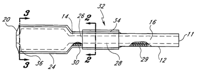
body. Referring to Figures 1 and 2, the present invention comprises an
extracorporeal vascular conduit 10.
The extracorporeal vascular conduit 10 comprises a first portion 12 and a
second portion 14 that, together,
comprise a substantial portion of the conduit 10. Both the first and second
portion 12, 14 comprise a first
synthetic biocompatible material 16, such as PTFE, including expanded PTFE
(ePTFE), or woven polyester, or
some other biocompatible material exhibiting similar characteristics and
qualities. The first portion 12
corresponds to the portion of the conduit 10 that is configured to reside
inside of the patient when the conduit
10 is applied to the patient. The second portion 14 corresponds to the portion
of the conduit 10 that is
configured to reside outside of the patient when the conduit 10 is applied to
the patient. The conduit 10 has a
distal end 18 comprising the distal end of the first portion 12 that is
configured to be secured to a patient's
vascular system. With such a configuration, the distal end 18 of the conduit
10 may be secured to a blood
vessel via, for example, an end-to-side anastomosis connection. If desired,
the biocompatible material 16 of
the first and second portions may have a reinforcing configuration, employing
either a discrete reinforcing
member or, preferably, a helical reinforcement that traverses the length of
the graft that comprises the
biocompatible material, sometimes referred to as beading.
The conduit 10 also has a proximal end 20 that is configured to connect to a
medical device (not
shown) usable in the treatment of a patient, including but not limited to a
pump, a vent, a sample site, a flow
meter, or an oxygenator. In the preferred embodiment, the proximal end 20 of
fhe conduit 10 comprises a
third portion 24 that, if desired, may comprise a tapered section with its
diameter larger from the distal to the
proximal. The tapered section permits accommodation of a medical device having
a diameter greater than the
diameter of the conduit 10 at the first and second portions 12,14. If desired,
the present catheter may include
a tapered section that has a smaller diameter from the distal to the proximal
to accommodate a medical device
having a diameter lesser than the diameter of the first and second portions of
the catheter. Of course, no
taper may be necessary, depending upon the size of the connection of the
medical device. In a preferred
embodiment, the inner diameter of the first and second portions 12,14 is 6.0
mm and the outer diameter is 7.2
mm. Also, the inner diameter of the proximal end of the third portion 24 is
0.375 (318) inches to permit
connection to medical devices having standard sized fittings.
Still referring to Figures 1 and 2, the present conduit 10 further comprises a
second synthetic material
26 that surrounds the biocompatible material substantially along the length of
the second portion 14 to form a
5
CA 02437796 2003-08-08
WO 02/064204 PCT/USO1/29542
second wall layer 28 of the conduit 10. In the preferred embodiment, the
second synthetic material is silicone
or urethane, although other materials having similar characteristics such as
durability, resiliency, and
imperviousness would be acceptable, including other polymers and rubbers. Like
the first synthetic
biocompatible material, the second synthetic material should be sufficiently
resilient to bend easily so as to
avoid significant discomfort to a patient during use. That is particularly
important where it is desired that the
patient be ambulatory when the extracorporeal vascular conduit is secured to
the patient.
The second synthetic material 26 functions to overcoat the first synthetic
biocompatible material 16 to
form the second wall layer 28 (or overcoat) to prevent exposure of the
biocompatible material 16 to the
ambient environment. With such an arrangement, the vascular conduit 10 may be
used extracorporeally for
extended periods of time without significantly adversely affecting the
patient's blood or its characteristics. The
biocompatible material 16 minimizes risk of thrombosis and inflammatory
response while the second synthetic
material prevents seepage of the blood through the graft conduit walls and
minimizes, thereby, risk of infection
or the risk of air emboli. Preferably, the distal end of the second synthetic
material 26 is located distal to the
transdermal penetration site when the conduit 10 is applied to the patient. In
other words, the point on the
conduit 10 that protrudes through the skin of the patient should be proximal
to the distal end of the second
synthetic material 26, although alignment of the second synthetic material 26
and the transdermal penetration
site would be acceptable while still preserving the functional advantages of
the present invention. The length of
the non-coated first portion depends upon where the treating physician desires
to locate the exit site relative to
the location of the connection to the patient's vascular system. For example,
where the exit site of the patient
is close to the vessel connection site, the length of non-coated portion would
be relatively short.
The second synthetic material 26 may be applied in one of multiple acceptable
manufacturing
techniques, including dipping the first biocompatible material into a source
of second synthetic material that
hardens and cures securely around the first biocompatible material after
removal from the source. Another
acceptable technique would be pre-forming a sleeve of second synthetic
material having an appropriate inner
diameter that is slipped over the first biocompatible material and positioned
at a desired location for welding or
bonding in place. An injection molding technique may also be acceptable. Other
techniques may be
acceptable that effectively secure the second synthetic material at a fixed
location around at least a portion of
the first synthetic biocompatible material to prevent seepage of the interior
fluid contents of the catheter to the
ambient and to prevent exposure of the same to air-borne contaminants.
Preferably, the third portion 24 of the conduit 10, including any tapered
section, is made from the
second synthetic material, such as silicone, PVC or polyurethane, or other
material exhibiting similar qualities
and characteristics. Where the material selected for the overcoat 30 and the
material selected for the third
portion are the same, they may be made integral to each other in an acceptable
manufacturing technique,
such as those identified above. If not of the same material, or even if of the
same material, the overcoat 28 of
the second portion 14 and the third portion 24 may be made discretely and
connected together using a
mechanical connection or bonding. In either case, it is desired that the
transition be as smooth as possible to
6
CA 02437796 2003-08-08
WO 02/064204 PCT/USO1/29542
avoid disrupting fluid flow and to avoid locations for potential thrombosis.
Preferably, regardless of the
manufacturing technique selected, the inner diameter of the second portion 14
of the conduit 10 is flush with
the inner diameter of the third portion 24 so that the fluid sees no
discontinuity in the wall surface, even where
a taper is provided. That requires that the inner diameter of the distal end
of the third portion 24 be the same
as the inner diameter of the proximal end of the second portion 14. With the
preferred embodiment, the
proximal end of the biocompatible material (i.e., the proximal end of the
second portion 14), therefore, abuts
against the distal end of the third portion 24. In addition, gradual
transitions are preferred from the inner
diameter of the second portion 14 to the inner diameter of the third portion
24. Such gradual transitions may
prevent undesirable turbulent flow.
Still referring to Figure 1, a preferred embodiment of the conduit further
comprises axial reinforcing
member 30 preferably extending through all or a part of the conduit 10 to
addstiffness to the conduit 10. The
reinforcing member 30 may be a helical coil, as is known in the art. It need
not be limited to helical coils,
however, as other reinforcement means may be used. The axial reinforcing
member 30 may not be
necessary so long as the conduit 10 is sufficiently stiff to avoid kinking
during use.
Still referring to Figures 1 and 2, the vascular conduit 10 further comprises
an interface portion 32
that comprises a sleeve 34 comprising a third synthetic material for
permitting enhanced securement of the
vascular conduit 10 to a patient during use. During use, particularly when the
patient is ambulatory, there is a
tendency for a transdermal conduit to move relative to the patient at the exit
site. Having an anchoring device
with a configuration and characteristic that permits a physician to suture the
conduit to the patient would be a
significant advantage. Preferably, the anchoring device comprises a sleeve 34
comprised of a third synthetic
material having a textile property to enhance the use of sutures as a means
for securing the catheter to the
patient. More preferably, the sleeve 34 is made of polyester or other material
having similar properties. The
sleeve 34 is bonded to the conduit 10 in a manner to prevent relative movement
between the sleeve and the
catheter. The length of the sleeve 34 should be sufficient to give some
flexibility to the physician in the
placement of the cannula with respect to the exit site. In one embodiment, the
sleeve 34 is manufactured
already bonded to the catheter with a length pre-selected to give flexibility
to the physician. If desired, the
sleeve length may be kept at a minimum but be manufactured discretely from the
conduit, permitting the
physician to locate the sleeve where desired and then to bond the sleeve to
the catheter after it is optimally
positioned on the catheter. For short-term use, a technique as simple as
clamping the extracorporeal portion
of the sleeve to the catheter wall without occluding the inner flow path might
be acceptable. For longer term
use, bonding with an adhesive at the proximal end of the sleeve with a bonding
material that would not travel
undesirably toward the skin and into the patient would be desired.
Referring to Figures 3 and 4, the conduit 10 may further comprise a small vent
36 in the vascular
conduit 10 at the proximal end of the third portion 24 to vent air undesirably
trapped in the conduit during use.
The vent 36 is sufficiently large to permit air to pass through but
sufficiently small to preclude the passage of
blood.
7
CA 02437796 2003-08-08
WO 02/064204 PCT/USO1/29542
As shown in Figure 5, the present invention may further comprise a vascular
shunt 38 having
opposing ends 40, 42 that are configured to attach to a patient's vascular
system. The vascular shunt ends
40, 42 may be secured to a blood vessel via, for example, an end-to-side
anastomosis connection. Like the
first and second portions 12, 14 of the conduit 10, the vascular shunt 38
comprises a first biocompatible
material 16, such as PTFE, including ePTFE, or woven polyester. The vascular
shunt provides an alternative
path for blood flow, and as a result, the vascular shunt remains free from
thrombi and blood can freely flow.
The vascular shunt 38 comprises one or more access ports 44 for connecting the
extracorporeal conduit 10.
The access port 44 may be, for example, a self-sealing membrane or a bio-
compatible valve. In this
embodiment, therefore, the conduit can be repeatably connected and
disconnected to the patients vascular
system, via the shunt 38 through the access ports) 44 without degrading the
vessel wall strength. The
advantage of this alternative embodiment is that a patient may be subject to
periodic treatments (or periodic
blood monitoring or drug infusion) without having to repeatably connect and
disconnect to the patient's blood
vessel. With this arrangement, the treating physician need only connect the
vascular conduit 10 to the
vascular shunt 38 and treat the patient as desired.
As can be seen in Figure 6, another embodiment of the present invention
comprises a conduit 110
comprising a plurality of discrete smaller conduits 46, each of which may be
connected to the patient's
vascular system at different locations at the distal end 18 of the vascular
conduit 10. By providing multiple
connection conduits 46, smaller conduits can be used while maintaining a
sufficient volume of blood flow. This
addresses, among other things, sealing problems encountered when large
conduits are connected to small
vessels. The connection conduits 46 converge at a junction 48 proximal to the
point of blood vessel
penetration, but distal of the penetration site through the patient's body so
that blood flows out of the body in
one conduit. Each of the connection conduits 46 may be connected to a
patient's vascular system via, for
example, an end-to-side anastomosis connection.
Figure 7 shows another application of the embodiment illustrated in Figure 6
wherein the vascular
conduit 10 comprises a plurality of connection conduits 54, 56. The connection
conduits 54, 56 are separated
at their distal ends 58, 60 and each is configured to connect to different
blood vessels within the patient's
vascular system. The connection conduits 54, 56 converge at a junction 62,
which is located within the first
portion 12. Each of the distal ends 58, 60 may be connected to a patient's
vascular system via, for example,
an end-to-side anastomosis connection. in this way, blood may flow out of two
different blood vessels in the
patient's vascular system into the conduit 10. Of course, the conduit 10 can
also be used to carry blood into
two different blood vessels through the two lumens 50, 5'2.
In an alternative embodiment shown in Figure 8, the vascular conduit 10 may pe
configured so that
the first portion 12 is made discrete from the second portion 14 so as to be
repeatably disconnectable. In
other words, it is contemplated that a mechanical connection be provided at
the junction of the first and second
portions to permit connection and disconnection thereof without adversely
affecting fluid flow when connected
or adversely affecting the patient when disconnected. Obviously, some means
for abating blood flow would be
8
CA 02437796 2003-08-08
WO 02/064204 PCT/USO1/29542
necessary with such an alternative embodiment, such as a valve, preferably
positioned just outside the
patient's body. By doing so, the abatement means may be easily accessed when
it is desired to connect or
disconnect the first and second discrete portions during treatment. With
application of the present inventive
extracorporeal graft catheter, the abatement means may be a hemostat to clamp
the proximal end of the first
portion that protrudes a short distance outside the patient. With longer term
and extended application, a more
durable and safe valve may be employed. The advantage of this alternative
embodiment is that a patient may
be subject to periodic treatments (or periodic blood monitoring or drug
infusion) without having to remove the
distal portion of the extracorporeal graft from the patient's blood vessel.
With this arrangement, the treating
physician need only connect the second portion of the catheter to the
abatement means at the proximal end of
the first portion and treat the patient as desired.
Thrombosis is a common reaction when blood comes into contact with foreign
matter inside or
outside of the vasculature. This can interfere with treatments involving
contact with foreign matter, such as the
conduits herein described. This problem is especially acute in longer term
treatments where significant build-
up can occur due to the length of time blood is flowing in the vascular
conduits. As a result, certain coatings
can be beneficial if applied to cannulae inserted into the vasculature. For
example, an anti-thrombotic coating
is especially useful for long-term treatments because it prevents adhesion of
blood components to the coated
surface, which might otherwise eventually block or severely restrict a lumen.
For this reason, at least the
interior of the first portion 12, the second portion 14 and the third portion
24 may have an anti-thrombotic
coating. Also, if any other vascular conduit component is exposed to the
interior lumens) of the vascular
conduit 10, it too may have an anti-thrombotic coating, if desired.
Because patients using this vascular conduit preferably are ambulatory, there
is an increased risk of
infection at the patient's exit site. Consequently, anti-microbial or anti-
bacterial coating may be beneficial,
especially in long-term treatments. When placed at least on the exterior
surface of the vascular conduit 10,
this coating reduces the chance of infection occurring at or near the
patient's exit site. Of course, any securing
device used in connection with the vascular conduit 10, such as the sleeve 34,
may also advantageously use
an anti-microbial or anti-bacterial coating to reduce the risk of infection of
the patient's exit site.
A preferred method of use of the present invention comprises the steps of (a)
providing an
extracorporeal vascular conduit comprising a first synthetic biocompatible
material that extends substantially
the length of the catheter, a second synthetic coating material employed over
the portion of the catheter that
extends outside the patient's body so as to form generally first and second
portions of the catheter, and a third
synthetic interface material to enhance securement of the catheter to the
patient's skin, (b) securing a distal
end of the extracorporeal vascular conduit to the patient's vascular system,
and (c) connecting a proximal end
of the extracorporeal vascular conduit to a pump, monitor, or other medical
device used in andlor during the
treatment of the patient. The present method could further include the steps
of (d) providing a vascular shunt
comprising a conduit made of synthetic biocompatible material, (e) securing a
first end of the shunt and a
second end of the vascular shunt to the patient's vascular system, and (f)
securing a distal end of the
9
CA 02437796 2003-08-08
WO 02/064204 PCT/USO1/29542
extracorporeal vascular conduit to the vascular shunt when it is desired to
effect treatment of the patient.
Other variations in these two methods are contemplated that provide for the
advantages described herein.
The present invention has, as one advantage, effectively permitting extended
extracorporeal blood
diversion during treatment of a patient. For example, the present invention
could be used with the system and
method for treating, inter alia, congestive head failure that was developed by
Orqis Medical, Inc., formerly Fore
Flow Corporation. Details of such system and method are found in U.S. Serial
No. 091166,055, now U.S.
Patent No. to Boiling, and U.S. Serial Nos. 091289,231 to Boiling, 09/470,841
to Boiling et al.,
and 091552,979 to Boiling et al., each of which are incorporated in their
entirety by reference. The present
invention could be particularly useful in enhancing the beneficial effects of
such a system on the patient by
minimizing the potential adverse effects of using synthetic materials for
extracorporeal blood flow. The present
invention could also be particularly useful where there is a desire to
establish a single connection to the
patient's vascular system for repeated monitoring of blood or for repeated
infusion of drugs or other fluids over
an extended period of treatment. Where it is desired to implement the system,
as described in the above-
identified patent applications incorporated by reference herein, in a manner
where the pump is positioned
external to the patient, a treating physician may connect the present
extracorporeal vascular conduit 10 at both
the inflow connection site and the outflow connection site; e.g., the left
axillary artery and the left femoral
artery, respectively.
In an alternative embodiment of the present extracorporeal vascular conduit,
more than one lumen
may be provided. In the embodiments described above, a single lumen was
provided. Where it desired to
have more than one path for fluid flow at a single site, a multi-lumen
extracorporeal vascular conduit may be
employed. Because it is contemplated that the present invention vascular
conduit would be surgically
connected to the patient's vasculature, the multi-lumen embodiment may be
fashioned in at least one of two
ways. In one version, a single housing having two lumens created therein may
be provided, wherein the
single housing is made of biocompatible material for substantially all of the
first and second portions, with a
protective coating provided on substantially all of the second portion
intended to project outside the patient's
body. The distal ends of the two lumens may then project outside the housing
in a manner that would permit
connection of each lumen separately to two positions on the same blood vessel
or to two separate blood
vessels. Likewise, the proximal ends of the two lumens would project outside
the housing in a manner that
would permit connection of each lumen to two separate medical devices or to an
inflow and outlet end of a
single pump. In an alternative version, the two lumens would be discrete but
secured together so as to
eliminate an integrating housing.
With regard to anchoring the present invention extracorporeal conduit to a
patient, anchoring devices
other than the sleeve 34 would be acceptable. For example, as shown is Figure
9, a semi-circular bracket 70
having a inner diameter approximately equal to the outer diameter of the
conduit near the skin exit and having
tabs extending outwardly from the conduit near the skin could be used. The
bracket should be dimensioned
such that the semi-circular portion accepts a portion of the conduit,
providing a friction fit with the conduit when
CA 02437796 2003-08-08
WO 02/064204 PCT/USO1/29542
the bracket is secured to the patient, The outwardly extending tabs could be
connected to the skin to
immobilize the conduit, preventing movement of the conduit with respect to the
vessel to which it is attached.
The outwardly extending tabs might be made with holes or some other feature to
facilitate immobilization of
the conduit via, for example, sutures.
Another suitable example of an anchoring mechanism would be a ring 72 having
an inner perimeter
approximately equal to the outer perimeter of the conduit near the skin exit.
The ring would be slideable with
respect to the conduit, but would provide sufficient friction fit to
immobilize the conduit with respect to the
vessel. As with the bracket, the ring would likely be made with some type of
anchoring feature. This could
include flanges extending outwardly from the ring on the side of the ring that
lies between the patient and the
conduit housing. These flanges could have suturing feature, such as holes or
posts making securing of the
anchoring device easier and less prone to break free from the skin.
Yet another example anchoring mechanism that could be used in conjunction with
the ring or the
semi-circular bracket described above would be a Velcro pad 74 with medical
grade adhesive on the back
side, which could be secured to the patient's skin. A mating Velcro portion
could be affixed to the ring, bracket
or other similar anchoring device, immobilizing the conduit with respect to
the vessel to which it is attached.
Another anchoring device would be a cloth loop 76 which could be wrapped
around the conduit near
the patient's exit site. This loop could be pulled sufficiently tight to
provide a snug fit around the conduit. The
ends of the cloth could be used to suture the conduit to the patient to
immobilize the conduit and prevent
relative motion between the conduit and the patient's vessels. Also, suturing
features could be attached to the
ends of the cloth strip to facilitate securement of the cloth loop anchoring
device to the patient. As discussed
above, the Velcro approach could also be used with the cloth loop to
immobilize the conduit.
Suitable materials for the anchoring devices include silicones, polymers (for
example, polyethylene
and polyurethane), rubber and.others known to those skilled in the art. Of
course, these materials and
anchoring devices are merely examples of the numerous different structures
that can be used to immobilize
the conduit to prevent relative motion between the conduit and the patients
vessel.
The invention may be embodied in other specific forms without departing from
its spirit or essential
characteristics. The described embodiment is to be considered in all respects
only as illustrative and not
restrictive and the scope of the invention is, therefore, indicated by the
appended claims rather than by the
foregoing description. All changes which come within the meaning and range of
equivalency of the claims are
to be embraced within their scope.
11