Note: Descriptions are shown in the official language in which they were submitted.
1
i
CA 02438496 2003-08-14
- 1
ELECTRONIC DEVICE
BACKGROUND OF THE INVENTION
Field of the Invention
The present invention relates to an electronic
device containing a circuit board mounted with an integrated
circuit element such as a CPU or an LSI requiring measures
against heat generation in a single case.
Related Background Art
In recent years, there is a trend toward a heavy use
of an element provided with numerous semiconductors or a
semiconductor integrated circuit element such as a CPU or an
LSI having a microelectronic circuit whose internal wires are
connected as a single solid in a special method. The
integrated circuit element having the microelectronic circuit
generates a large amount of heat in a process of operation.
A temperature rise of the integrated circuit element may
cause a defect such that the operation of the integrated
circuit element becomes unstable. A further temperature rise
may destroy the semiconductor. Therefore, conventionally a
heat sink has been mounted on the integrated circuit element
for a heat exchange between the heat sink and an air to cool
the integrated circuit element by releasing heat of the
integrated circuit element to the air, thereby preventing the
integrated circuit element such as a CPU or an LSI from
getting unstable in its operation due to the high temperature
or from being destroyed by heat.
0
CA 02438496 2003-08-14
- 2 -
On the other hand, a server is provided with
numerous electronic devices using the integrated circuit
element as set forth in the above for use in a data
communication network with communication lines or a computer
network (LAN) for a high-speed data transfer with privately
owned lines within a limited range such as a building or a
premise. In other words, a significant temperature rise
occurs due to the operation of numerous integrated circuit
elements in a server of the kind described above. Therefore,
conventionally there has been applied a method of cooling an
entire room where the server is installed with a cooling unit
and taking the cold air into the electronic devices to cool
the integrated circuit elements.
In the conventional method, however, in which the
cold air is taken with a propeller fan (air blower) provided
at the rear of the electronic device and the cold air
generated within the electronic device is blown against the
integrated circuit element, the cold air is applied to only a
part of the integrated circuit element inefficiently in
cooling.
Therefore, a part of the cold air taken into a case
with the air blower has been ejected to an outside of the
electronic device without cooling the integrated circuit
element.
SUMMARY OF THE INVENTION
The present invention has been provided to resolve
i
CA 02438496 2003-08-14
- 3 -
the above conventional problem. It is an object of the
present invention to provide an electronic device capable of
efficiently cooling an integrated circuit element provided in
such a way as to enable a heat exchange on a cold plate.
In accordance with a first aspect of the present
invention, there is provided an electronic device containing
a circuit board mounted with an integrated circuit element
requiring measures against heat generation in a single case,
comprising: a cold plate mounted on the integrated circuit
element in such a way as to enable a heat transfer from the
integrated circuit element; a heat exchanger for cooling
brine heated by the cold plate by circulating the brine; a
fan casing forming an air way from a blower fan at an opening
on a surface of the case to the heat exchanger; a reserve
tank for storing the brine and a pump for circulating the
brine, which are provided in order in a brine flow from the
heat exchanger to the cold plate; and a linear brine passage
formed in the cold plate and having at least one pair of back
and forth channels.
With these features, the electronic device has a
control unit for controlling at least one of the blower fan
and the pump in such a way as to maintain a temperature of
the cold plate at +70°C or lower when a temperature of a
periphery of the case is at +35°C or higher.
Furthermore, with the above features, a plurality of
the integrated circuit elements are mounted on the circuit
board and the cold plate is provided for each of the
> >
CA 02438496 2003-08-14
- 4 -
integrated circuit elements.
Still further, with the above features, heat
conductive material is provided between the integrated
circuit element and the cold plate, and the integrated
circuit element is put between the cold plate and a socket
holding the integrated circuit element by using elastic
material.
In addition, with the above features, the blower fan
is a cross flow fan, which is provided in the vicinity of the
opening of the case and supplies an air taken from the
opening linearly along a long side of the heat exchanger.
With the above features, the fan casing is
configured in such a way as to take in an air from below with
its opening facing downward.
Furthermore, with the above features, the blower fan
is a cross flow fan, which is provided in the vicinity of the
opening of the case and discharges an air heated by the heat
exchanger from the opening.
Still further, with the above features, the fan
casing is configured in such a way as to discharge an air to
above with its opening facing upward.
Additionally, with the above features, an angle of
the opening of the fan casing is adjustable.
With the above features, the cold plate comprises
two pieces of heat conductive material laminated to each
other with a concavity and a convexity formed thereon engaged
with each other so as to sandwich a pipe through which the
> >
CA 02438496 2003-08-14
- 5 -
brine flows between them.
Furthermore, with the above features, there is heat
conductance between the heat conductive material and the pipe
and sheet material having elasticity is sandwiched
therebetween.
Still further, with the above features, bottlenecks
are provided in positions corresponding to the upstream of
the brine flow within the pipe put between two pieces of the
heat conductive material.
With the above features, the heat exchanger
comprises a plurality of plates having heat conductance and a
pipe through which the brine flows with penetrating the
plates in such a way as to enable a heat transfer, wherein a
part of a casing covering the heat exchanger is formed by the
fan casing or an extension thereof, and wherein the fan
casing has a shape causing the air to be collected on the
plates of the heat exchanger.
Furthermore, with the above features, a plurality of
vent holes are provided in the position opposed to the
circuit board on a surface of the case enclosing the circuit
board.
Still further, with the above features, the vent
holes are formed by cutting and raising a part of the case.
With the above features, a line forming a
circulation path of the brine circulating between the cold
plate and the heat exchanger is arranged in one side portion
within the case and a bottom face of the side portion is
> >
CA 02438496 2003-08-14
- 6 -
formed lower than the heat exchanger.
With the above features, the reserve tank and the
pump are arranged in the side portion within the case.
With the above features, the bottom face of the side
portion within the case slopes downwardly in a predetermined
direction.
Furthermore, with the above features, a brine
detection sensor is provided in the lowest position of the
bottom face within the case or in the vicinity thereof and a
detection unit is provided for outputting an alarm in
response to an output from the brine detection sensor.
Still further, with the above features, a plurality
of cooling fins are provided in the side opposed to the
integrated circuit element on the cold plate.
With the above features, an air blower for the cold
plate is mounted on the cooling fins.
With the above features, the air blower for the cold
plate has a centrifugal fan.
Furthermore, with the above features, the heat
exchanger comprises a plurality of plates having heat
conductance and a pipe through which the brine flows with
penetrating the plates in such a way as to enable a heat
transfer, wherein an outlet from the heat exchanger for the
brine flowing from the pipe to the cold plate is provided in
a position higher than the cold plate.
BRIEF DESCRIPTION OF THE DRAWINGS
Y
CA 02438496 2003-08-14
Fig. 1 is a front view of a server rack containing
stacked servers,
each of which
is an embodiment
of an
electronic
device according
to the present
invention;
Fig. 2 is a perspective view of the server as an
embodiment f the electronic device according to the present
o
invention;
Fig. 3 is a perspective view showing a condition
where a top cover of a case of the server shown in Fig. 2;
Fig. 4 is a top sectional view of the server shown
in Fig. 3;
Fig. 5 is a vertical side view of a front end of the
server shown in Fig. 2;
Fig. 6 is an expanded view of vent holes on a side
surface of he case of the server shown in Fig. 2;
t
Fig. 7 is a vertical rear view of the server shown
in Fig. 3;
Fig. 8 is a vertical side view of the server shown
in Fig. 3;
Fig. 9 is a side view of an integrated circuit
element and
a cold plate
mounted on
a circuit
board of the
server shown in Fig. 3;
Fig. 10 is an exploded perspective view of the cold
plate shown
in Fig. 9;
Fig. 11 is an electrical diagram of a brine cooling
unit of the
server shown
in Fig. 3;
Fig. 12 is a flowchart illustrating a control
operation of the microcomputer shown in Fig. 11;
CA 02438496 2003-08-14
Fig. 13 is another flowchart illustrating the
control operation of the microcomputer shown in Fig. 11;
Fig. 14 is still another flowchart illustrating the
control operation of the microcomputer shown in Fig. 11;
Fig. 15 is a flowchart illustrating a control
operation of another embodiment of the microcomputer shown in
Fig. 11;
Fig. 16 is another flowchart illustrating the
control operation of another embodiment of the microcomputer
shown in Fig. 15;
Fig. 17 is a top sectional view of a server of
another embodiment of an electronic device according to the
present invention;
Fig. 18 is a vertical side view of a rear of the
server shown in Fig. 17;
Fig. 19 is a perspective view of a cold plate and an
integrated circuit element of the server of another
embodiment of the electronic device according to the present
invention;
Fig. 20 is a diagram showing another mounting
structure of the integrated circuit element to the cold plate
in the electronic device according to the present invention;
Fig. 21 is a diagram showing still another mounting
structure of the integrated circuit element to the cold plate
in the electronic device according to the present invention;
Fig. 22 is a diagram showing further another
mounting structure of the integrated circuit element to the
CA 02438496 2003-08-14
g _
cold plate in the electronic device according to the present
invention;
Fig. 23 is a front view showing another embodiment
of the cold plate in the electronic device according to the
present invention; and
Fig. 24 is a sectional view taken along line A-A of
Fig. 23.
DETAILED DESCRIPTION OF THE PREFERRED EMBODIMENTS
The preferred embodiments of the present invention
will now be described in detail hereinafter with reference to
the accompanying drawings.
In the diagrams, a server (a single server) 1 of
this embodiment is central to providing various services to
computers connected to a network. It is mounted in a frame
2B of a server rack 2 having casters 2A for carrying at the
bottom. A plurality of the servers are vertically installed
in a plurality of stages. Each server 1 contains a circuit
board 5 mounted with a plurality of (or a single)
semiconductor integrated circuit elements 6 such as LSIs or
CPUs. Furthermore, a controller 52 is provided at the lower
part of the server rack 2 for management of task allocation
to the servers 1 or of operating conditions.
The server 1 contains and comprises the circuit
board 5, a floppy disk drive 31, a CD-ROM. drive 32, a supply
circuit (power) 9, a connector (I/O) 8, and other electronic
components, a plate-fin type heat exchanger 11, a cross flow
CA 02438496 2003-08-14
- 10 -
fan 14, a brine circulation pump 15, a reserve tank 26 for
storing brine, and a brine cooling unit 10 comprising cold
plates 16 mounted in such a way as to enable a heat transfer
from integrated circuit elements 6 and for cooling the
integrated circuit elements 6, within a thin rectangular case
3, for example, having a height of 45 mm, a width of 450 mm,
and a depth of 530 mm. The case 3 has a front face 3A, a
bottom face 3B, a rear face 3C, right and left side faces 3D
and 3D, with a top face covered with a detachable top cover 4.
In this case, the floppy disk drive 31 and the CD-
ROM drive 32 face the front face 3A of the case 3 on its
right and an opening 30 is formed on the left-hand side of
the components. Furthermore, the heat exchanger 11 is
arranged within the case 3 in such a way as to correspond to
the inward portion of the opening 30. The heat exchanger 11
comprises a plurality of plates 12 having a transcalent
property such as sheet aluminum arranged at 1-mm to 5-mm
intervals and a meandering aluminum pipe 13, through which
brine flows as described below, penetrating the plates 12 in
such a way as to enable a heat transfer. If the plates 12
are arranged at short intervals, an air filter 34 having an
appropriate size of mesh described later is preferably used.
If they are arranged at long intervals,.a safety structure
such as a slit is used instead of the air filter 34.
Furthermore, a fan casing 39 for the cross flow fan
14 is arranged opposing to the opening 30 in the side of the
opening 30 of the heat exchanger 11. Accordingly, the cross
a ~ CA 02438496 2003-08-14
- 11 -
flow fan 14 is provided in the vicinity of the opening 30.
The fan casing 39 is for use in forming an air way
communicating from the opening 30 to the heat exchanger 11.
The opening 33 of the fan casing 39 faces the outside with
oriented downward from the opening 30 of the case 3 and the
air filter 34 for dust exclusion is attached to the opening
33.
A curved opening angle adjustment plate 36 is
attached like a window roof to the upper edge of the opening
33 of the fan casing 39.. The opening angle adjustment plate
36 is free to be latched or released by ribs 37A, which is
longitudinally provided in a protruding condition at
specified intervals on a latch plate 37 provided in the upper
portion of the inside of the opening 33. By changing the
positions of the ribs 37A by moving them longitudinally for
latching, an amount of protrusion from the upper edge of the
opening 33 can be changed in three steps. This enables a
change of an amount of protrusion in the extension of the fan
casing 39, in other words, a change of the downward angle of
the opening 33 in three steps such as, for example, 15 deg,
deg, and 45 deg to horizontal, thus achieving an effective
air suction from a direction adjusted to the angle.
In this connection, in a computer room where this
type of server rack 2 is installed, there is a circulation in
25 which a cooling air is blown from the floor side and the air
is taken into the ceiling side. On the other hand, a
plurality of the servers 1 are installed in the server rack 2
CA 02438496 2003-08-14
- 12 -
as set forth in the above. Therefore, by adjusting the
downward angle of the opening 33 to be smaller (closer to
horizontal) for the upper servers 1 and adjusting the
downward angle of the opening 33 to be larger (more
downwardly oriented) for the lower servers 1, the cooling air
coming up from the floor side can be easily and smoothly
taken into the case 3 from the openings 33 of the servers 1
in respective stages for circulation within the case 3. The
cooling air (cold air) is circulated in the case and then
discharged from the rear face (back face) of the case 3.
The fan casing 39 is provided with a flap 38 for
rectification located at the back of the cross flow fan 14,
in other words, in the side of the heat exchanger 11, to
prevent the air from the cross flow fan 14 from leaning to
one side of the heat exchanger 11. In addition, the fan
casing 39 is extended on both sides integrally with an air
trunk member 41 extending to both sides of the plurality of
plates 12 of the heat exchanger 11 at the back of the fan
casing 39 and to the lower side of the plates 12. It should
be noted that the air trunk member 41 may be formed by an
extension separated from the fan casing 39.
In this connection, the upper edges of the plates 12
of the heat exchanger 11 contact against the top cover 4 of
the case 3, while the lower edges of the plates 12 contact
against the under surface of the air trunk member 41
contacting against the bottom face 3B of the case 3.
Furthermore, the right and left faces of the air trunk member
CA 02438496 2003-08-14
- 13 -
41 are located in the right and left sides of the outermost
plates 12, thus forming the casing of the heat exchanger 11.
The air trunk member 41 of the fan casing 39 causes an air
from the cross flow fan 14 to center on the plates 12 of the
heat exchanger 11. This causes an air taken into the case 3
to be guided only to portions between the plates 12 of the
heat exchanger, thus preventing deterioration in the heat
exchange efficiency that occurs if the air is leaked to other
portions and thus improving the efficiency of the heat
exchange with a brine flow in the heat exchanger 11 described
later.
In this case, the cross flow fan 14 is placed
opposite in the longitudinal (horizontal) direction to the
air inflow side (front side) of the heat exchanger 1.l. An
air taken from the opening 30 (opening 33) is supplied
linearly in the longitudinal direction of the heat exchanger
11. This enables an efficient air blow to the heat exchanger
11 by supplying the air taken into the case 3 by the cross
flow fan 14 from the opening 30. Note that reference
character 14M indicates a motor (a DC motor whose revolution
speed changes according to an applied voltage) of the cross
flow fan 14 and it is attached to an outer face of the fan
casing 39.
On the other hand, vent holes 42 and 42 are formed
in the left and right portions on the rear face 3C of the
case 3 and a blower fan 43 for exhaust ventilation is
attached to each of the vent holes 42 and 42. The circuit
CA 02438496 2003-08-14
- 14 -
board 5 is located between the heat exchanger 11 and the vent
holes 42 and 42 and attached to the bottom face 3B of the
case 3. Furthermore, the power supply circuit 9 is placed
opposite to the left vent hole 42 inside. In addition, on
the left and right side faces 3D and 3D of the case 3 in the
position enclosing the circuit board 5, a plurality of vent
holes 44 are formed by inwardly cutting and raising a part of
the side faces 3D and 3D opposite to the circuit board 5 (Fig.
6). The cut and raised portions for the vent holes 44 are
oriented obliquely toward behind.
When the cross flow fan 14 starts to operate, air
taken into the case 3 from the opening 30 is blown against
the heat exchanger 11 and passes through the portions between
the plates 12 to reach the circuit board 5. Thereafter, the
air passes around the cold plates 16 and the power supply
circuit 9 and it is sucked into the blower fans 43 and 43 so
as to be discharged to the outside from the vent holes 42 and
42. This forms a series of air ways from the opening 30 to
the vent holes 42 and 42 in the case 3.
In addition, a fresh air (an air before passing the
heat exchanger 11) is taken into the vent holes 44 formed on
the side faces 3D and 3D by the above ventilation, passes
around the cold plates 16 on the circuit board 5, and is
discharged from the vent holes 42, 42 similarly. This
prevents an abnormal temperature rise in the inside of the
case 3 by using the air exposed to the heat exchange with the
heat exchanger 11 and improves an air cooling effect of the
CA 02438496 2003-08-14
- 15 -
cold plates 16. Furthermore, the vent holes 44 are formed by
the cut and raised configuration, thereby improving
productivity of the case 3.
An outlet 13A for the brine in the pipe 13 of the
heat exchanger 11 is arranged at the upper end on the left
side of the front as facing toward the heat exchanger 11. A
pipe 46 connected to the outlet 13A is connected to an inlet
of the reserve tank 26. A pipe 47 connected from an outlet
of the reserve tank 26 is connected to a suction opening of
the pump 15. A discharge opening of the pump 15 is connected
to an inlet of an aluminum pipe 23 of the cold plates 16. An
outlet of the pipe 23 is connected to a brine inlet 13B of
the pipe 13 for the heat exchanger 11 via a pipe 48, thus
forming a ring brine circulation path of the brine cooling
unit 10. More specifically, the reserve tank 26 and the pump
15 are arranged in order in a brine stream flowing from the
outlet 13A of the heat exchanger 11 to the cold plates 16.
Furthermore, the brine is enclosed in the ring brine
circulation path.
The brine is a liquid heat medium that will never be
boiled by the heat generation of the integrated circuit
elements 6: antifreeze liquid is enclosed in this embodiment.
In addition, the brine can be normal water, purified water,
or HFE (hydrofluoroether).
In this case, the inlet 13B of the pipe 13 for the
heat exchanger 11 is located just under the outlet 13A on the
left side of the front of the heat exchanger 11. The inlet
CA 02438496 2003-08-14
- 16 -
13B and the outlet 13A (at least the outlet 13A) are arranged
in positions higher than the cold plates 16. The bottom face
3B of the case 3 in the position corresponding to the
downward portion of the heat exchanger 11 is set up higher
than other parts (Fig. 7). This forms a lower portion 49
lower than a bottom edge of the heat exchanger 11 on the left
side of the heat exchanger 11. All of the outlet 13A and the
inlet 13B of the pipe 13 for the heat exchanger 11, the pipes
45 and 48, the reserve tank 26, the pump 15, and the pipe 47
(these pipes form a brine circulation line) are arranged in
the lower portion 49 or above it correspondingly.
The circuit board 5 is raised with spacers and
attached in a position higher than the upper surface of the
lower portion 49. The reserve tank 26 and the pump 15 are
arranged at a front end on the lower portion 49. Furthermore,
the upper surface of the lower portion 49 is sloping forward
downwardly as a whole (Fig. 8). At the lowest forward end, a
detection sensor 51 is attached to detect brine standing
there, if any.
According to this constitution, even if brine leaks
due to any crack or damage on the connections between the
outlet 13A and the inlet 13B of the pipe 13 for the heat
exchanger 11, the pipes 46, 47, 48, and 23, the reserve tank
26, and the pump 15 or on these components, the brine leakage
flows down along the slope of the lower portion 49 on the
bottom face 3B of the case 3 so as to be collected in the
front end inside the lower portion 49. This enables as much
CA 02438496 2003-08-14
- 17 -
delay as possible and leads to a prevention of a disadvantage
such as a failure caused by the brine leakage into the
circuit board 5, the integrated circuit elements 6 mounted
thereon, the pump 15, and the heat exchanger 11.
Particularly the outlet 13A of the heat exchanger 11 is
located in a position higher than the cold plates 16.
Therefore, even if a poor connection occurs between the
outlet 13A and the pipe 48, it becomes possible to minimize
the amount of brine leaking from the heat exchanger 11 until
the pump 15 is stopped as described later. The brine having
leaked to the lower portion 49 is detected.by the detection
sensor 51 as described above and then the pump 15 is halted
and an alarm is output as described later. Between the lower
portion 49 and the heat exchanger 11 and the circuit board 5,
a rib 50 is arranged in a standing condition from the bottom
face 3B of the case 3 to prevent the brine leakage from
flowing into the circuit board 5.
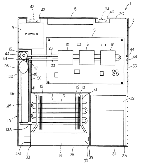
On the circuit board 5, the plurality of (three in
this embodiment, though one is possible) semiconductor
integrated circuit elements 6 are mounted as set forth above.
The integrated circuit elements 6 are arranged linearly at
specified intervals and they are mounted on the circuit board
5 via sockets, respectively (Fig. 9). The cold plates 16 are
mounted on the integrated circuit elements 6, respectively,
in such a way as to exchange heat and grease 24 having high
heat conductivity is applied to a portion between each cold
plate 16 and each integrated circuit element 6. The grease
CA 02438496 2003-08-14
- 18 -
24 makes the integrated circuit element 6 and the cold plate
16 closely stick together, thereby transmitting the heat of
the integrated circuit element 6 to the cold plate
efficiently. Note that it is also possible to use elastic
sheet material having good heat conductance as described
later instead of the grease 24.
The cold plate 16 is formed, for example, by
laminating two aluminum plates (heat conductive material)
having high heat conductivity (good heat conductance) with
caulking. More specifically, the cold plate 16 comprises a
plate-type base member 17 as the heat conductive material
located on the side of the integrated circuit element 6 and a
plate-type cover member 18 as the heat conductive material
laminated and stick close to the base member 17, with the
pipe 23 sandwiched between the base member 17 and the cover
member 18 as set forth in the above (Fig. 9).
The base member 17 has a plurality of (in this
embodiment, a pair of) pipe grooves 21 from its front end to
rear end: the pipe grooves 21 are formed in parallel at
specified intervals (Fig. 10). The pipe grooves 21 and 21
are formed into a concavity as a semicircular arc
corresponding to the outer circumferential shape of the pipe
23 and both pipe grooves 21 and 21 are formed at a given
distance from both sides of the base member 17 on the inside
thereof.
In addition, an engagement groove (concavity) 19
having a given depth and a given width is formed between one
CA 02438496 2003-08-14
- 19 -
pipe groove 21 and one side portion of the base member 17
from the front end to rear end of the base member 17. The
engagement groove 19 is formed in an almost U-shaped cross
section and in a concavity on the base member 17 almost in
parallel to the pipe groove 21. Furthermore, an engagement
groove 19A is formed in parallel to the pipe groove 21 from
the front end to rear end of the base member 17 between both
pipe grooves 21 and the engagement groove 19A is formed in
the same manner as for the engagement groove 19.
The base member 17 also has an engagement protrusion
(convexity) 20B having a given height and a given width
formed from its front end to rear end. The engagement
protrusion 20B is formed in such a way as to be protruding
from the base member 17 and it is located between one pipe
groove 21 and the engagement groove 19A in such a way as to
be formed in parallel to the pipe groove 21. Furthermore,
the base member 17 has an engagement protrusion 20C formed
from its front end to rear end. The engagement protrusion
20C is formed in the same shape as for the engagement
protrusion 20B and it is located on the other side of the
other pipe groove 21, which is the opposite side to the
engagement groove 19A. In other words, the engagement groove
19, the pipe groove 21, the engagement protrusion 20B, the
engagement groove 19A, the pipe groove 21, and the engagement
protrusion 20C are formed at specified intervals in order
from one side of the base member 17, and all of them are
formed on one side of the base member 17.
CA 02438496 2003-08-14
- 20 -
On the other hand, a plurality of (two) pipe grooves
21 are formed on the cover member 18. These pipe grooves 21
are formed in the same shapes as for the pipe grooves 21
formed on the base member 17. The pipe grooves 21 on the
cover member 18 are formed in the positions opposite to the
pipe grooves 21 on the base member 17 when the cover member
18 is placed on the base member 17 in superposed relation, by
which the pipes 23 and 23 are sandwiched between the pipe
grooves 21 formed on the base member 17 and the cover member
18.
At this point, there is provided sheet material 53
having heat conductance and elasticity made of a thin
graphite sheet or the like having a thickness of 50 ~, or so
between the pipe 23 and the cover member 18 so as to be
sandwiched between the base member 1? and the pipe 23 and the
cover member I8. Note that the sheet material can be put on
the other side of the pipe 23 or on the side of the base
member 17. Furthermore, it can be provided between the
integrated circuit element 6 and the cold plate 16 as set
forth in the above or can be attached to the upper surface of
the cold plate 16. As the material of the sheet material 53,
it is possible to use a copper foil.
The sheet material 53 has good heat conductance in
the surface direction, thus enabling a good heat transfer
between the pipe 23 and the base member 17 and the cover
member 18 in a wide range and improving the heat conductance
efficiency. The action causes a very smooth heat transfer
CA 02438496 2003-08-14
- 21 -
from the integrated circuit element 6 to the brine flowing
through the pipe 23 of the cold plate 16. Note that the
grease described above can be applied to a surface where the
sheet material 53 is not provided (for example, the upper
surface of the base member l7 in Fig. 10).
In this case, the cover member 18 has engagement
protrusions 20 and 20A similar to the engagement protrusions
20B and 20C from its front end to rear end. The engagement
protrusions 20 and 20A are formed in positions opposite to
the engagement grooves 19 and 19A on the base member 17. The
both engagement protrusions 20 and 20A are pushed and mated
in the engagement grooves 19 and 19A, respectively, when the
cover member 18 is placed on the base member 17 in superposed
relation. Furthermore, the cover member 18 has engagement
groves 19B and 19C similar to the engagement grooves 19 and
19A from its front end to rear end. The engagement grooves
19B and 19C are formed in positions opposite to the
engagement protrusions 20B and 20C on the base member 17.
When the cover member 18 is placed on the base member 17 in
superposed relation, the engagement protrusions 20B and 20C
are pushed and mated in the engagement.grooves I9B and 19C,
respectively.
More specifically, for the cold plate 16, the pipes
23, 23 and the sheet material 53 described above are
sandwiched between the base member I7 and the cover member 18
(pipe grooves 21 and 21) in superposed relation. Then, the
engagement protrusions 20 and 20A and the engagement
,. CA 02438496 2003-08-14
- 22 -
protrusions 20B and 20C are pushed and mated in the
engagement groves 19 and 19A and the engagement grooves 19B
and 19C, respectively, for caulking, thereby fixing the base
member 17 and the cover member 18 by close contact. At this
point, the peripheries of the pipes 23 and 23 are closely
fixed to the base member 17 and the cover member 18 (via the
sheet material). Both of the pipes 23 and 23 are protruding
from the front and rear ends of the base member 17 and the
cover member 18.
Three cold plates 16 in the above configuration are
prepared in this embodiment. The ends of the pipes 23 of the
cold plates 16 are connected with connectors 23A. At this
point, the cold plates l6 are connected to each other on the
three integrated circuit elements 6 mounted on the circuit
board 5 with dimensions corresponding to the locations, and
the pipes 23 of the cold plate 16 in one side are connected
to each other with a bend pipe (circular pipe) 23B.
With this connection of the cold plates 16, a linear
brine passage with a pair of back and forth channels is
formed between the cold plates 16. It is also possible to
make a linear brine passage having a plurality of pairs of
back and forth channels between the cold plates 16 by
providing more pipes 23. The cold plates 16 are fixed with a
contact to the respective integrated circuit elements 6 via
the grease 24 having a high heat conductivity as described
above (Fig. 9).
In the three cold plates 16 connected in this manner,
~" CA 02438496 2003-08-14
- 23 -
the left ends of the pipes 23 for the cold plates 16 located
in the opposite position to the bend pipe 23B are connected
to the discharge opening from the pump 15 and to the pipe 48
connected to the heat exchanger 11 in the upper part of the
lower portion 49.
Subsequently, referring to Fig. 11, there is shown
an electrical diagram of the brine cooling unit 10 for the
server 1. In this diagram, there is shown a general-purpose
microcomputer comprising a control unit and a detection unit.
An input port of the microcomputer 54 is connected to
thermistors THl, TH2, and TH3 for detecting temperatures of
the cold plates 16 with being attached to the cold plates 16
so as to exchange heat (or for detecting the temperatures in
the vicinity of the integrated circuit elements 6) and to a
thermistor TH4 for detecting a brine return temperature to
the heat exchanger 11 with being attached to the inlet 13B of
the pipe 13 for the heat exchanger 11 or to the pipe 48
connected thereto in such a way as to exchange heat.
Furthermore, the input port of the microcomputer 54
is also connected to a resistance 56 (such as a volume) for
setting the maximum value Tmax (for example, +80°C) of the
brine return temperature and to a mode switch 57. A voltage
varying based on a temperature detection of the detection
sensor 51 is applied to an A/D (analog/digital conversion)
input port of the microcomputer 54. A power ON (coupled to
the power supply) reset signal is input to the reset input
port of the microcomputer 54. Furthermore, the microcomputer
r CA 02438496 2003-08-14
- 24 -
54 exchanges data to or from the controller 52.
A signal output from an output port of the
microcomputer 54 is supplied to switching power supply
circuits SW1 and SW2 via a buffer and output voltages of the
switching power supply circuits SW1 and SW2 are controlled
within a range of +6V to +12V in this embodiment. A
transistor 59 controlling whether a relay 58 (relay coil) is
energized is connected via a buffer to the microcomputer 54,
which controls the ON/OFF switching. In addition, the output
of the microcomputer 54 is connected to an LED indicator 61.
A voltage DC +12V output from the power supply
circuit 9 is supplied to the switching power supply circuits
SW1 and SW2. An output from the switching power supply
circuit SW1 is supplied to a motor 15M of the pump 15 via a
resistance 62 and a normally open contact 58A of the relay 58.
An output from the switching power supply circuit SW2 is
supplied to a motor 14M of the cross flow fan 14 via a
resistance 63 and a normally open contact 58B of the relay 58.
Furthermore, a resistance 64 and a series circuit of
a light-emitting diode of a photo coupler PH1 are connected
in parallel with the resistance 62 in the output side of the
switching power supply circuit SW1. An output of a
phototransistor of the photo coupler PH1 is connected to the
input port of the microcomputer 54. A resistance 66 and a
series circuit of a light-emitting diode of a photo coupler
PH2 are connected in parallel with the resistance 63 in the
output side of the switching power supply circuit SW2. An
t ~, CA 02438496 2003-08-14
- 25 -
output of a phototransistor of the photo coupler PH2 is
connected to the input port of the microcomputer 54.
With the above constitution, an operation of the
brine cooling unit 10 for the server 1 with controls of the
microcomputer 54 will be described hereinafter by referring
to flowcharts shown in Figs. 12 to 14. When the power is
turned on, a power ON reset signal is input to the
microcomputer 54 in step Sl in Fig. 12. For the reset signal,
the microcomputer 54 uses an edge trigger of DC +5V to be a
power supply of the relay 58 and the photo couplers PH1 and
PH2.
Subsequently, the microcomputer 54 determines the
maximum Tmax of the brine return temperature set at the
resistance 56 and stores it into the storage unit (memory) in
step S2. In this embodiment, Tmax is assumed to be set to
+80°C. Then, the microcomputer 54 starts counting on a timer
(for example, 5-min timer), which is its own function, in
step 53. In step S4, it determines whether a time of five
minutes has elapsed since the timer counting is started.
Unless the time has elapsed, the control progresses to step
S5, in which voltage signals indicating an output of DC +12V
are output to the switching power supply circuits SW1 and SW2,
respectively, and then the transistor 59 is turned on to
energize the relay 58. The energized relay 58 closes the
contacts 58A and 58B.
By this operation, DC +12V is supplied to the motor
15M of the pump 15 and the motor 14M of the cross flow fan I4,
CA 02438496 2003-08-14
- 26 -
thereby both of which are operated with the maximum power.
When the cross flow fan 14 is operated, an air is sucked from
the opening 30 of the case 3 as described above and blown
against the heat exchanger 11 linearly in a longitudinal
direction. Thereafter, the air after cooling the plates 12
of the heat exchanger 11 and the pipe 13 passes around the
cold plates 16 on the circuit board 5 and the power supply
circuit 9 for cooling. Then, the air is discharged to the
outside from the vent holes 42 and 42 by means of the blower
fans 43 and 43.
As set forth in the above, a fresh air is taken into
the vent holes 44 formed on the side faces 3D and 3D and
passes around the cold plates 16 on the circuit board 5 and
the power supply circuit 9 for cooling. Thereafter, the air
is discharged to the outside from the vent holes 42 and 42
similarly.
On the other hand, an operation of the pump 15
causes brine to be discharged from the discharge opening. In
a process of passing through the pipe 23, the brine exchanges
heat with the cold plates 16 sequentially and then reaches
the inlet 13B of the pipe 13, flowing through the pipe 48.
The brine that has entered the inlet 13B exchanges heat with
the pipe 13 and the plates 12 in a process of meandering in
the pipe 13 within the heat exchanger 11 and it is cooled by
the ventilating air from the cross flow fan 14.
The brine discharged from the outlet 13A of the pipe
13 for the heat exchanger 11 reaches the reserve tank 26 via
w CA 02438496 2003-08-14
2~ -
the pipe 46 and then it is sucked from the suction opening of
the pump 15 via the reserve tank 26 to repeat the circulation.
In this manner, the brine cooled by the heat exchanger 11
cools the cold plates 16 and then the cold plates 16 cool the
integrated circuit elements 6.
In step S6, the microcomputer 54 determines whether
the phototransistors of the photo couplers PHl and PH2 are on.
If no output is generated from the switching power supply
circuit SWl nor SW2, the light-emitting diodes of the photo
coupler PH1 and PH2 do not emit light and the
phototransistors are off. If the phototransistors of the
photo couplers PH1 and PH2 are on, the microcomputer 54
determines that the outputs are generated from the switching
power supply circuits SW1 and SW2 and then returns to step S4.
If the phototransistors of the photo couplers PH1 and PH2 are
off, an error is expected in the pump 15 or the cross flow
fan 14 and therefore the control progresses from step S6 to
step S7 to indicate an error on the LED indicator 61, thereby
outputting an alarm.
After turning on the power supply, the microcomputer
54 continues the operation of the cross flow fan 14 and the
pump 15 at the maximum power until the timer counts up the
predetermined time to cope with the heat generation at the
startup of the server 1_and to stabilize the cooling capacity
of the brine cooling unit 10. When the timer counts up the
time after an elapse of five minutes since the power supply
is turned on, the microcomputer 54 progresses from step S4 to
CA 02438496 2003-08-14
- 28 -
step S8 to determine whether the brine return temperature
detected by the thermistor TH4 is equal to or higher than the
maximum value Tmax.
If the temperature of the brine that has returned
after the heat exchange with the cold plates 16 rises to a
temperature equal to or higher than Tmax, the microcomputer
54 progresses to step S12 to continue the operation of the
cross flow fan 14 and the pump 15 at the maximum power in the
same manner as for the above, indicates an error on the LED
indicator 61, and returns to step S8. This suggests a
condition where the cold plates 16 do not cool the integrated
circuit elements 6 effectively, by which an alarm is output.
On the other hand, if the brine return temperature
is lower than Tmax in step S8, the microcomputer 54
progresses to step S9 to download temperatures of the cold
plates 16 detected by the thermistors THl, TH2, and TH3.
Then, the highest temperature is selected out of the
temperatures detected by the thermistors THl to TH3 and it is
considered T0. Subsequently, it is determined whether TO is
equal to or higher than Tmax minus 5 (or +75°C) in step 510.
If it is equal to or higher than the temperature, the
microcomputer 54 progresses to step S14 to operate the cross
flow fan 14 and the pump 15 at the maximum power in the same
manner as for the above. Then, it returns to step S8.
If TO is lower than Tmax minus 5 in step 510, the
microcomputer 54 progresses to step S11 to determine whether
TO is equal to or higher than Tmax minus 40 (or +40°C). If
CA 02438496 2003-08-14
- 29 -
TO is equal to or higher than Tmax minus 40 and lower than
Tmax minus 5 (in other words, equal to or higher than +40°C
and lower than +75°C), the microcomputer 54 progresses to
step S20 in Fig. 13.
In step 520, increase or decrease values ~V of the
output voltages of the switching power supply circuits SW1
and SW2 are obtained from a data table previously computed by
the PID (proportional plus integral plus derivative) or fuzzy
operation on the basis of OT obtained from a deviation
(change) of the current TO from the previous T0. A routine
cycle in this case is, for example, 0.5 sec. In the
operation in step S20, the computation is made in such a way
that the power of the pump 15 or the cross flow fan 14 is.
increased in response to a brine temperature rise and it is
decreased in response to a temperature drop so that the
temperature of the cold plates 16 becomes a setting value
within the range of +50°C to +70°C when the temperature of
the periphery of the case 3 is equal to or higher than +35°C.
The setting value can also be controlled by the controller 52
according to the operating ratio of the server 1 or can be
arbitrarily set manually.
Subsequently, in step 521, the microcomputer 54
controls a voltage signal Vnew output to the switching power
supply circuit SW1 and SW2 to be the current voltage signal
plus t1V in the above. Then, in step 522, it corrects the
voltage signal so that the voltage signal Vnew does not
exceed the range of the lower limit DC +8V to the upper limit
a . CA 02438496 2003-08-14
- 30
+12V and energizes the relay 58. By this operation, the pump
15 and the cross flow fan 14 are operated at the adjusted
power.
In step 524, the microcomputer 54 determines whether
the phototransistors of the photo couplers PH1 and PH2 are on
in the same manner as for the above. If no output is
generated from the switching power supply circuits SW1 and
SW2, the light-emitting diodes of the photo couplers PHl and
PH2 emit no light, and the phototransistors are off, an error
is indicated on the LED indicator 61 to output an alarm in
the same manner as for the above in step 525. If the
switching power supply circuits SW1 and SW2 are normal, the
microcomputer 54 returns to step S8.
On the other hand, in step 511, if TO is lower than
Tmax minus 40 (or +40°C), the microcomputer 54 progresses to
step S15 in Fig. 14 to determine whether the mode switch 57
is on. Assuming that the mode switch 57 is on at this point,
the.microcomputer 54 progresses from step S15 to step S17 to
output a voltage signal of DC +8V to the switching power
supply circuit SWl, to output a voltage signal of OV to the
switching power supply circuit SW2, and to energize the relay
58.
This causes the pump 15 to be operated at the lowest
power, by which the minimum brine circulation is secured in
the brine circulation path of the brine cooling unit 10,
while the cross flow fan 14 is halted to interrupt the
ventilation. Accordingly, if the brine return temperature is
' CA 02438496 2003-08-14
- 31 -
lower than +40°C, the microcomputer 54 maintains the minimum
cooling of the integrated circuit elements 6 with the brine
cooling unit 10 when the mode switch 57 is on. In step 518,
the microcomputer 54 determines whether an output is
generated from the switching power supply circuit SWl by
means of the phototransistor of the photo coupler PH1 in the
same manner as for the above. If no output is generated, an
error is indicated on the LED indicator 61 similarly. In
either case, the microcomputer 54 returns to step S8.
On the other hand, if the mode switch 57 is off, the
microcomputer 54 progresses from step S15 to step S16 to
output a voltage signal of OV to the switching power supply
circuits SW1 and SW2 so that the relay 58 is not energized
and to return to step S8. In other words, if the brine
return temperature is lower than +40°C and the mode switch 57
is off, the microcomputer 54 halts the cooling of the
integrated circuit elements 6 with the brine cooling unit 10.
Subsequently, referring to Figs. 15 and 16, there is
shown a flowchart of the control with the microcomputer 54
according to another embodiment. The controller 52 provided
in the server rack 2 computes an operating ratio of the
integrated circuit elements 6 through data communication with
each server 1. A temperature rise of the integrated circuit
elements 6 can be grasped from the operating ratio and the
operating ratio is transmitted to the microcomputer 54. This
flowchart shows a control with the operating ratio.
More specifically, when the power supply is turned
' ~ CA 02438496 2003-08-14
- 32 -
on, a power ON reset signal as described above is input to
the microcomputer 54 in step S31 in Fig. 15. Subsequently,
the microcomputer 54 determines the maximum value Tmax of the
brine return temperature set at the resistance 56 and stores
it into the storage unit (memory) in step 532. In this case,
Tmax is assumed to be set to +80°C, too. Then, the
microcomputer 54 starts counting on the timer (5-min timer
described above), which it has as its own function, in step
533. In step 534, the microcomputer 54 determines whether a
time of five minutes has elapsed since the timer counting is
started. Unless the time has elapsed, the microcomputer 54
progresses to step S35 to output a voltage signal indicating
that DC +12V is output to the switching power supply circuits
SWl and SW2 to turn on the transistor 59, thereby energizing
the relay 58. The energized relay 58 causes the contacts
58A and 58B to be closed.
By this operation, DC +12V is supplied to the motor
15M of the pump 15 an the motor 14M of the cross flow fan 14
and both are operated at the maximum power in the same manner
as for the above. The microcomputer 54 determines whether
the phototransistors of the photo couplers PHl and PH2 are on
in step 536. If outputs are generated from the switching
power supply circuit SWl and SW2 and the phototransistors of
the photo couplers PH1 and PH2 are on, the microcomputer 59
determines that the outputs are generated from the switching
power supply circuits SWl and SW2 and returns to step 534.
If the phototransistors of the photo couplers PHl and PH2 are
' CA 02438496 2003-08-14
- 33 -
off, the microcomputer 54 progresses from step S36 to step
S37 to indicate an error on the LED indicator 61, thereby
outputting an alarm.
After turning on the power supply, the microcomputer
54 continues the operation of the cross flow fan 14 and the
pump 15 at the maximum power until the timer counts up the
predetermined time to stabilize the cooling capacity of the
brine cooling unit 10. When the timer counts up the time
after an elapse of five minutes since the power supply is
turned on, the microcomputer 54 progresses~from step S34 to
step S38 to determine whether the brine return temperature
detected by the thermistor TH4 is equal to or higher than the
maximum value Tmax.
If the temperature of the brine that has returned
after the heat exchange with the cold plates 16 rises to a
temperature equal to or higher than Tmax, the microcomputer
54 progresses to step S42 to continue the operation of the
cross flow fan 14 and the pump 15 at the maximum power in the
same manner as for the above, indicates an error on the LED
indicator 61, and returns to step 538. This gives an alarm
of an abnormal high temperature of the integrated circuit
elements 6.
On the other hand, if the brine return temperature
is lower than Tmax in step 538, the microcomputer 54
progresses to step S39 to download operating ratios F1, F2,
and F3 of the integrated circuit elements 6 sent from the
controller 52. Then, the highest operating ratio is selected
' ' CA 02438496 2003-08-14
- 34 -
out of the operating ratios Fl to F3 and it is considered F0.
Subsequently, it is determined whether FO is, for example,
80% or higher in step S40. If it is so, the microcomputer 54
progresses to step S44 to operate the cross flow fan 14 and
the pump 15 at the maximum power in the same manner as for
the above. Then, the microcomputer returns to step 538.
If FO is lower than 80% in step 540, the
microcomputer 54 progresses to step S41 to determine whether
FO is, for example 40% or higher. If FO is 40% or higher and
lower than 80%, the microcomputer 54 progresses to step S50
in Fig. 16.
In step 550, increase or decrease values OV of the
output voltages of the switching power supply circuits SW1
and StnT2 are obtained from a data table previously computed by
the PID (proportional plus integral plus derivative) or fuzzy
operation on the basis of a deviation (change) of the current
FO from the previous F0. A routine cycle in this case is,
for example, 0.5 sec. In the operation in step S50, the
computation is made in such a way that the power of the pump
15 or the cross flow fan 14 is increased in response to a
brine temperature rise and it is decreased in response to a
temperature drop so that the temperature of the cold plates
16 is +70°C or lower when the temperature of the outside of
the case 3 is +35°C. The setting value can also be
controlled by the controller 52 according to the operating
ratio of the server 1 or can be arbitrarily set manually.
Subsequently, in step 551, the microcomputer 54
CA 02438496 2003-08-14
- 35 -
controls a voltage signal Vnew output to the switching power
supply circuit SW1 and SW2 to be the current voltage signal
plus 0V in the above. Then, in step 552, it corrects the
voltage signal so that the voltage signal Vnew does not
exceed the range of the lower limit DC +8V to the upper limit
+12V and energizes the relay 58. By this operation, the pump
and the cross flow fan 14 are operated at the adjusted
power. This control enables a rapid increase of the cooling
capacity against a sudden heat generation of the integrated
10 circuit elements 6 so as to prevent an occurrence of a damage
on the integrated circuit elements.
In step 554, the microcomputer 54 determines whether
the phototransistors of the photo couplers PH1 and PH2 are on
in the same manner as for the above. If no output is
15 generated from the switching power supply circuits SW1 and
SW2, the light-emitting diodes of the photo couplers PHl and
PH2 emit no light, and the phototransistors are off, an error
is indicated on the LFD indicator 61 to output an alarm in
the same manner as for the above in step 555. If the
switching power supply circuits SW1 and SW2 are normal, the
microcomputer 54 returns to step 538.
On the other hand, in step 541, if FO is lower than
40~, the microcomputer 54 progresses to step S15 in Fig. 14
to execute the same control thereafter. The control in Fig.
14 is the same as one described above. Therefore, its
description is omitted here. As set forth in the above, the
brine cooling unit 10 can be controlled by using the
' ' CA 02438496 2003-08-14
- 36 -
operating ratios of the integrated circuit elements 6.
At this point, if the detection sensor 51 detects
the brine, the microcomputer 54 indicates an error on the LED
indicator 61 to output an alarm in response to the detection.
At the same time, it outputs a voltage signal of OV to the
switching power supply circuit SW1 to halt the pump 15. This
minimizes the brine leakage. A voltage signal, for example,
of the maximum +12V is output to the switching power supply
circuit SW2 so that an air is blown into the case 3 at the
maximum power to secure the cooling in the case 3. Otherwise,
if the detection sensor 51 detects a brine leakage, the
operation of all electric components can be halted including
the integrated circuit elements 6.
As set forth hereinabove, if the brine leaks in the
connections between the outlet 13A and the inlet 13B of the
pipe 13 for the heat exchanger 11, the pipes 46, 47, 48, and
23, the reserve tank 26, and pump 15 and the brine leakage in
the front end within the lower portion 49 on the bottom face
3B of the case 3 is detected by the detection sensor 51, an
alarm is output on the LED indicator 61. Therefore, a user
can carry out maintenance rapidly against an error caused by
the brine leakage. In addition, the pump 15 is halted in
this condition, by which the forced brine leakage is also
stopped. Furthermore, since the outlet 13A of the heat
exchanger is located in the position higher than the cold
plates 16 as described above, a leakage at the outlet 13A, if
any, halts the Bump 15, by which the brine in the heat
' ' CA 02438496 2003-08-14
- 37 -
exchanger 11 remains inside. Therefore, the brine leakage
from the heat exchanger 11 is minimized.
Subsequently, referring to Figs. 17 and 18, there
are shown configurations of the server 1 regarding an
arrangement of the cross flow fan 14 according to another
embodiment. In these diagrams, the same reference characters
as in Figs. 4 and 5 refer to corresponding parts or have like
functions. In this case, an opening 67 is formed on the rear
face 3C of the case 3 and a fan casing 39 of the cross flow
fan 14 is arranged correspondingly on the inside of the
opening 67. Accordingly, the cross flow fan 14 is provided
in the vicinity of the opening 67.
The fan casing 39 in this case is for use in forming
an air way from the cross flow fan 14 to the heat exchanger
11 in front thereof. The opening 33 of the fan casing 39
faces the outside with oriented upward from the opening 67 of
the case 3. The filter 34 for dust exclusion as described
above is attached to the opening 33.
When the cross flow fan 14 is operated, an air
around the circuit board 5 in the case 3 in the front of the
cross flow fan is sucked. This causes an air suction from
the opening 30 on the front face 3A and the vent holes 44 on
the side faces 3D and 3D described above. After the heat
exchange of the heat exchanger 11, the cross flow fan 14
discharges the air to the outside from the opening 33
(opening 67). This enables the cooling of the heat exchanger
11 and the cold plates 16 of the brine cooling unit 10 for
CA 02438496 2003-08-14
- 38 -
cooling the integrated circuit elements 6 in the same manner
as for the above.
In this connection, a curved opening angle
adjustment plate 36 is attached to the lower edge of the
opening 33 of the fan casing 39. The opening angle
adjustment plate 36 is free to be latched or released by ribs
37A longitudinally provided in a protruding condition at
specified intervals on a latch plate 37 provided in the lower
portion on the inside of the opening 33 in this case, too.
By changing the positions of the ribs 37A by moving them
longitudinally for latching, it becomes possible to change an
amount of protrusion from the lower edge of the opening 33 in
three steps. This enables changes in three steps such as,
for example, 15 deg, 30 deg, and 45 deg to horizontal as an
upward angle of the opening 33.
As described above, in an office where this type of
server rack 2 is installed, an air-conditioning air is blown
from the floor side. The plurality of servers 1 are attached
to the server rack 2 as set forth in the above. The upward
angle of the opening 33 is adjusted to be smaller (closer to
horizontal) for the upper servers 1 and the upward angle of
the opening 33 is adjusted to be larger (more upwardly
oriented) for the lower servers 1. This makes it possible to
discharge the air in the case 3 to the outside easily,
thereby further improving the cooling efficiency of the
integrated circuit elements 6.
The method of air conditioning for a place where the
~
. CA 02438496 2003-08-14
- 39 -
server rack 2 is installed is not limited to the air blowing
from the floor side, but includes cases of air conditioning
using a floor-type or ceiling-type air conditioner and via a
duct.
Referring to Fig. 19, there is shown an example of a
configuration where cooling fins 68 are mounted on the cold
plate 16. In this diagram, the same reference characters as
in Figs. 9 and 10 refer to like parts. In this case, however,
the integrated circuit element 6 is sandwiched between the
cold plate 16 and the socket 7 and the cold plate 16 is
detachably fixed to the socket 7 by means of the elastic
metal leaf spring 69 as elastic material.
Furthermore, a plurality of aluminum cooling fins 68
are mounted on the upper face of the cover member 18 of the
cold plate 16, in other words, to the face' opposite to the
lower face contacted by the integrated circuit element 6 in
this case. In this condition, a notch 68A into which a leaf
spring 69 can be inserted is formed in the cooling fins 68.
Still further, an air blower 7l for the cold plate 16 is
mounted on the upper face of the cooling fins 68. The air
blower 71 comprises a centrifugal turbo fan having a small
thickness. It sucks air from the side of the cooling fins 68
located downward and discharges it from the discharge opening
72 on the side face.
According to the above constitution, the cold plate
16 is powerfully cooled down by the heat dissipation from the
cooling fins 68 and the forcible ventilation with the air
CA 02438496 2003-08-14
- 40 -
blower 71 in addition to the cooling with the brine.
Therefore, the integrated circuit element 6 can be cooled
rapidly and accurately. Furthermore, since the air blower 71
is a centrifugal fan, an expansion of the height is minimized
to achieve the miniaturization.
Subsequently, referring to Fig. 20, there is shown
another embodiment of the mounting structure of the cold
plate 16 and the integrated circuit element 6. In this
diagram, the same reference characters as in Figs. 9 and 10
refer to like parts. In this structure, however, the cold
plate 16 is attached to the bottom face 3B of the case 3 and
the circuit board 5 is located in the upper portion. As
shown in this diagram, fitting seats 17A and 17B are provided
in the left and right lower ends of the base member 17 of the
cold plate 16. By threading screws 76 into screw holes
provided in the fitting seats 17A and 17B, the cold plate 16
is fixed to the bottom face 3B of the case 3. The sheet
material having the heat conductance as described the above
is preferably put between the cold plate 16 and the bottom
face 3B.
The integrated circuit element 6 is arranged so as
to be contacted by the upper face of the cover member 18 of
the cold plate 16 mounted on the bottom face 3B of the case 3
via a heat conductor (not shown) such as grease. Furthermore,
the socket 7 electrically connected to the integrated circuit
element 6 and the circuit board 5 electrically connected to
the socket are mounted on the integrated circuit element 6.
CA 02438496 2003-08-14
- 41 -
The circuit board 5, the socket 7, and the integrated circuit
element 6 are integrally fixed to the bottom face 3B of the
case 3 by fitting a pair of elastic metal leaf springs 73A
and 73B as elastic material over the socket 7 and the cold
plate 16 as described below. The leaf springs 73A and 73B
are as shown formed by a pair of components comprising a pair
of arms and angle connections for connecting the rear anchors
of the arms.
In other words, as shown in Fig. 20, one ends of the
pair of leaf springs 73A and 73B are fixed to both side walls
of the base member 27 of the cold plate 16 with screws 74.
The other ends of the pair of leaf springs 73A and 73B are
detachably engaged with engagement grooves 7A and 7B having
an angled engagement face formed on both side walls of the
socket 7. Thereby, the integrated circuit element 6 is
attached to the bottom face 3B of the case 3 via the cold
plate 16 by means of contraction force of the leaf springs
73A and 73B.
With the fixing structure, the integrated circuit
element 6 can be easily attached to the case 3 in the
condition where it is sandwiched between the cold plate 16
and the socket 7. In this case, the cold plate 16 is in very
close contact with the case 3 and therefore its heat
conductance is high. Accordingly, the~effect of heat
dissipation is high, thus enabling effective cooling of the
integrated circuit element 6 that is an electronic component
causing a heat build-up in combination with the brine cooling
~
CA 02438496 2003-08-14
- 42 -
action.
Referring to Fig. 21, there is shown still another
embodiment of the mounting structure of the cold plate 16 and
the integrated circuit element 6. In this diagram, the same
reference characters as in Figs. 9 and 10 refer to like parts.
In this case, the circuit board 5 is fixed to the bottom face
3B of the case 3 in the raised condition as described in the
first embodiment. The socket 7 electrically connected to the
circuit board 5 is provided on the upper face of the circuit
board 5. The integrated circuit element 6 is electrically
connected and attached to it on the socket 7. In this case,
a screw hole 77 is formed in the center of the upper face of
the cover member 18 of the cold plate 16. An elastic metal
leaf spring 78 as elastic material has a profile almost in M
shape. A flat 78A is formed in the center of the leaf spring
78. The flat 78A is fixed to the upper face of the cover
member 18 of the cold plate 16 with a screw 81 to be threaded
into the screw hole 77. Furthermore, both ends 78B and 78B
of the leaf spring 78 are detachably engaged in the
engagement grooves 7A and 7B formed on both side walls of the
socket 7. Thereby, the cold plate 16 is integrally pressed
against the integrated circuit element 6 by means of the
contraction force of the leaf spring 78 so as to support the
integrated circuit element 6 between the cold plate 16 and
the socket 7 for mounting them on the circuit board 5.
Referring to Fig. 22, there is shown still another
embodiment of the mounting structure of the cold plate 16 and
' ' CA 02438496 2003-08-14
- 43 -
the integrated circuit element 6. In this case, the circuit
board 5 is also fixed to the bottom face 3B of the case 3 in
the raised condition and the socket 7 electrically connected
to the circuit board 5 is provided on the upper face of the
circuit board 5. The integrated circuit element 6 is
electrically connected and attached to it on the socket 7.
The cold plate 16 is arranged on the upper face of
the integrated circuit element 6 via the grease 24. An
elastic metal leaf spring 81 has a profile almost in M shape
in the same manner as for the above. Its center is put in
contact with the center of the upper surface of the cover
member 17 of the cold plate 16. Both sides of the leaf
spring 81 are inserted into a portion between two pipes 23
and 23 so as to be engaged in a portion between them.
Furthermore, both ends 81A and 81A are detachably engaged in
the engagement grooves 7A and 7B formed on both side walls of
the socket 7 respectively. Thereby, the cold plate l6 is
integrally pressed against the integrated circuit element 6
by means of a contraction force of the leaf spring 81 so as
to support the integrated circuit element 6 between the cold
plate 16 and the socket 7 for mounting them on the circuit
board 5. In this condition the leaf spring 81 is engaged in
the portion between the pipes 23 and 23 and therefore it is
not displaced without fixing with screws.
Also by using the above fixing structure, the
integrated circuit element 6 can be easily mounted on the
circuit board 5 in the condition where the integrated circuit
' CA 02438496 2003-08-14
- 44 -
element 6 is put between the cold plate 16 and the socket 7.
Particularly in Fig. 22, screws for fixing the leaf spring
are unnecessary.
Subsequently, referring to Figs. 23 and 24, there is
shown another structure of the cold plate 16. In these
diagrams, the same reference characters as in Figs. 9 and 10
refer to like parts, too. In this condition, a single or a
plurality of (two in this embodiment) protrusions 82 are
formed in positions corresponding to the upstream of the
brine flow.
According to this structure, the pipe 23 is crushed
by the protrusions 82 at caulking of the base member 17 and
the cover member 18, by which bottlenecks 83 are formed by
the number of the protrusions 82 in positions corresponding
to the upstream of the brine flow.
With the formation of the bottlenecks 83 on the pipe
23, turbulent flows occur in the cold plate 16 when the brine
circulating in the pipe 23 passes through the bottlenecks 83
as shown in Fig. 24 at cooling the integrated circuit element
6. As a result, the brine is agitated and brine temperature
layers of peripheral and central portions of the pipe are
eliminated. This improves the cooling efficiency of cooling
the integrated circuit element 6.
Furthermore, the protrusions 82 are previously
formed in the pipe grooves 21 on the base member 17 and the
cover member 18 of the cold plate 16 and the bottlenecks 83
are formed by the protrusions 82 by crushing the pipe 23 at
' ' CA 02438496 2003-08-14
- 45 -
caulking of the members 17 and 18 for connection, and
therefore the manufacturing process of the cold plate 16 is
the same as the conventional one, thus bringing an increase
in production costs down.
While the present invention has been described in
connection with preferred embodiments with referring to
numerical values, it is to be understood that these values
are not limited to those specific embodiments and that the
power or capacity of the integrated circuit elements is
appropriately set according to a quantity or the like. In
addition, while the present invention has been described in
connection with preferred embodiments in which the
microcomputer 54 controls the power for the operation of the
pump 15 and the cross flow fan l4 on the basis of the brine
return temperature and the operating ratio of the integrated
circuit elements 6, the present invention is not limited to
those embodiments. On the contrary, it is intended to
include alternatives or modifications such that the pump 15
is regularly operated with a power control of the cross flow
fan 14 only or that the cross flow fan 14 is regularly
operated with a power control of the pump 15 only.
As set forth hereinabove, according to the present
invention, there is provided an electronic device containing
a circuit board mounted with an integrated circuit element
requiring measures against heat generation in a single case,
comprising: a cold plate mounted on the integrated circuit
element in such a way as to enable a heat transfer from the
~
CA 02438496 2003-08-14
- 46 -
integrated circuit element; a heat exchanger for cooling
brine heated by the cold plate by circulating the brine; a
fan casing forming an air way from a blower fan at an opening
on a suxface of the case to the heat exchanger; a reserve
tank for storing the brine and a pump for circulating the'
brine, which are provided in order in a brine flow from the
heat exchanger to the cold plate: and a linear brine passage
formed in the cold plate and having at least one pair of back
and forth channels. Therefore, the brine cooled by the heat
exchanger effectively cools down the integrated circuit
element through the cold plate.
This enables reliable or effective elimination of
disadvantages such that the integrated circuit element such
as a CPU or an LSI falls into an unstable operation or a
thermal damage due to a high temperature.
According to the present invention, with these
features, the electronic device has a control unit for
controlling at least one of the blower fan and the pump in
such a way as to maintain a temperature of the cold plate at
+70°C or lower when a temperature of a portion around the
periphery of the case is at +35°C or higher, thereby enabling
a rapid increase of the cooling capacity against a sudden
heat generation of the integrated circuit elements 6 so as to
- prevent an occurrence of a damage on the integrated circuit
elements.
Furthermore, according to the present invention,
with the above features, a plurality of the integrated
~
CA 02438496 2003-08-14
circuit elements are mounted on the circuit board and the
cold plate is provided for each of the integrated circuit
elements, thereby enabling effective cooling of each of the
plurality of integrated circuit elements. In this case, it
is possible to minimize a temperature difference between the
cold plates in the side of the upstream and of the downstream
of the brine flow, thus enabling equal cooling of the
integrated circuit elements provided in such a way as to
enable the heat transfer to the plurality of cold plates.
Particularly, the passage in the cold plates is linear,
thereby simplifying the piping structure and reducing the
brine circulation resistance, by which the integrated circuit
elements can be cooled efficiently.
Still further, according to the present invention,
with the above features, heat conductive material is provided
between the integrated circuit element and the cold plate,
and the integrated circuit element is put between the cold
plate and a socket holding the integrated circuit element by
using elastic material, thereby enabling very simple mounting
of the integrated circuit element and the cold plate.
According to the present invention, with the above
features, the blower fan is a cross flow fan, which is
provided in the vicinity of the opening of the case and
supplies an air taken from the opening linearly along a long
side of the heat exchanger, thereby enabling efficient
blowing of the air taken into the case from the opening by
the cross flow fan over the entire surface of the long side
~
. CA 02438496 2003-08-14
- 48 -
of the heat exchanger and thus improving the heat exchange
efficiency in the heat exchanger.
This improves the heat exchange efficiency between
the brine flow and the ventilation air in the heat exchanger,
thus improving the brine cooling efficiency of the integrated
circuit elements and enabling rapid and efficient cooling of
the integrated circuit elements.
According to the present invention, with the above
features, the fan casing is configured in such a way as to
take in an air from below with its opening facing downward,
by which an outside air (or cold air) can be taken into the
case from under the opening of the case. Particularly, if a
specific device is used to supply an air (or cold air) from
under the case, the air can be easily taken into the case,
thus further improving the cooling efficiency of the
integrated circuit elements.
Furthermore., according to the present invention,
with the above features, the blower fan is a cross flow fan,
which is provided in the vicinity of the opening of the case
and discharges an air heated by the heat exchanger from the
opening, thus enabling efficient discharging of the air
heated by the heat exchanger in the case.
This improves the heat exchange in the heat
exchanger and the cooling efficiency of the integrated
circuit elements, thus enabling rapid and efficient cooling
of the integrated circuit elements.
Still further, according to the present invention,
= CA 02438496 2003-08-14
- 49 -
with the above features, the fan casing is configured in such
a way as to discharge an air to the above with its opening
facing upward, by which the air heated in the case and having
a high temperature can be efficiently dissipated to the
outside. Particularly, if a specific device is used to
supply an air from under the case, the air in the case can be
easily discharged to the outside, thus further improving the
cooling efficiency of the integrated circuit elements.
According to the present invention, with the above
features, an angle of the opening of the fan casing is
adjustable. Therefore, for example, even if the electronic
devices are positioned one on top of another in a stacked
relationship in a plurality of stages, smooth air circulation
is achieved in the cases of the respective electronic devices
by adjusting the angle of the opening of the tan casing in
each stage.
According to the present invention, with the above
features, the cold plate comprises two pieces of heat
conductive material laminated to each other with a concavity
and a convexity formed thereon engaged with each other so as
to sandwich a pipe through which the brine flows between them,
thereby simplifying the structure of the cold plate and the
assembling workability and improving the productivity.
Furthermore, according to the present invention,
with the above features, there is heat conductance between
the heat conductive material and the pipe and sheet material
having elasticity is sandwiched therebetween, thereby
~
CA 02438496 2003-08-14
- 50 -
improving the heat conductivity between the heat conductive
material and the pipe by means of the sheet material. This
improves the heat exchange efficiency between the brine
flowing through the pipe and the heat conductive material
having the integrated circuit element, thus further improving
the cooling efficiency of the integrated circuit element.
Still further, according to the present invention,
with the above features, bottlenecks are provided in
positions corresponding to the upstream of the brine flow
within the pipe put between two pieces of the heat conductive
material. Thereby, turbulent flows occur when the brine
circulating in the pipe 23 passes through the bottlenecks.
As a result, the brine is agitated and brine temperature
layers of peripheral and central portions of the pipe are
eliminated, thus improving the cooling efficiency of cooling
the integrated circuit element.
According to the present invention, with the above
features, the heat exchanger comprises a plurality of plates
having heat conductance and a pipe through which the brine
flows with penetrating the plates in such a way as to enable
a heat transfer, wherein a part of a casing covering the heat
exchanger is formed by the fan casing or an extension thereof,
and wherein the fan casing has a shape causing the air to be
collected on the plates of the heat exchanger. Thereby, the
air taken into the case by the cross flow fan can be guided
only to the heat exchanger by means of the fan casing or its
extension partially forming the casing covering the heat
~
CA 02438496 2003-08-14
- 51 -
exchanger.
It is effective to eliminate a disadvantage such
that the heat exchange efficiency is decreased by a leakage
of the air taken into the casing by the cross flow fan into a
portion other than a portion between the plates forming the
heat exchanger. It improves the efficiency of the heat
exchange with the brine flow in the heat exchange and
improves the cooling efficiency of the integrated circuit
element with the brine, thus enabling rapid and accurate
cooling.
Furthermore, according to the present invention,
with the above features, a plurality of vent holes are
provided in the position opposed to the circuit board on a
surface of the case enclosing the circuit board. Thereby,
after the heating of the air taken into the case by the
blower fan from the opening by the heat exchange with the
heat exchanger, a fresh air can be further taken into the
case from the vent holes, thus preventing a disadvantage such
as a significant temperature rise in the case caused by the
air after the heat exchange with the heat exchanger.
Still further, according to the present invention,
with the above features, the vent holes are formed by cutting
and raising a part of the case. Thereby, the vent holes can
be easily formed, thus improving the productivity.
According to the present invention, with the above
features, a line forming a circulation path of the brine
circulating between the cold plate and the heat exchanger is
' ' CA 02438496 2003-08-14
- 52 -
arranged in one side portion within the case and a bottom
face of the side portion is formed lower than the heat
exchanger. Thereby, if a brine leakage occurs due to a poor
connection or any crack or damage on the line forming the
circulation path of the brine, the leaked brine stands on the
lower bottom face in the side portion. It is effective to
prevent a disadvantage such as an adverse effect of short-
circuit or the like on the integrated circuit element
arranged within the case caused by the brine leakage.
According to the present invention, with the above
features, the reserve tank and the pump are arranged in the
side portion within the case. Thereby, if any failure occurs
in the reserve tank or the pump, the brine that has leaked
from the reserve tank or the pump stands on the lower bottom
face in the side portion. Thus, it is effective to prevent
an adverse effect on the integrated circuit elements, which
may be caused by the brine leakage into the entire area
within the case.
According to the present invention, with the above
features, the bottom face of the side portion within the case
slopes downwardly in a predetermined direction. Thereby, the
brine that has leaked into the side portion within the case
is caused to stream down in a predetermined direction so as
to be collected, thus enabling a delay of the occurrence of
an effect on other devices mounted within the case.
Furthermore, according to the present invention,
with the above features, a brine detection sensor is provided
' ~ CA 02438496 2003-08-14
- 53 -
in the lowest position of the bottom face within the case or
in the vicinity thereof and a detection unit is provided for
outputting an alarm in response to an output from the brine
detection sensor. Thereby, if a brine leakage occurs, the
brine detection sensor detects it immediately and an alarm
can be output in response to the output from the detection
sensor. Therefore, a user can be quickly informed of the
occurrence of the abnormal condition.
It is effective to minimize the expansion of the
damage caused by the brine leakage, thus preventing an
adverse effect on the integrated circuit element mounted
within the case.
Still further, according to the present invention,
with the above features, a plurality of cooling fins are
provided in the side opposed to the integrated circuit
element on the cold plate. Thereby, the heat generated by
the integrated circuit element of the cold plate can be
cooled down by the cooling fins in addition to the cooling
with the brine, thus enabling rapid and accurate cooling of
the integrated circuit element.
According to the present invention, with the above
features, an air blower for the cold plate is mounted on the
cooling fins. Thereby, the cooling fins can be forcibly
cooled down by the air blower for the cold plate, thus
enabling more rapid and accurate cooling of the integrated
circuit element.
According to the present invention, with the above
' CA 02438496 2003-08-14
- 54 -
features, the air blower for the cold plate has a centrifugal
fan. Thereby, the cold plate can be forcibly cooled down by
using the fan of relatively low profile, thus achieving a
miniaturization of the device.
Furthermore, according to the present invention,
with the above features, the heat exchanger comprises a
plurality of plates having heat conductance and a pipe
through which the brine flows with penetrating the plates in
such a way as to enable a heat transfer, wherein an outlet
from the heat exchanger for the brine flowing from the pipe
to the cold plate is provided in a position higher than the
cold plate. Thereby, if a poor connection or any crack or
damage occurs in the outlet from the heat exchanger, the
brine leakage from the heat exchanger can be minimized. It
is effective to minimize an adverse effect on the integrated
circuit element mounted within the case.