Note: Descriptions are shown in the official language in which they were submitted.
CA 02438535 2003-08-15
WO 02/066799 PCT/US02/04452
AIR TURBINE FOR COMBUSTION ENGINE
BACKGROUND
1. Field of the Invention
The present invention relates to a device for causing a vortex in the intake
or exhaust of a combustion engine. The device can be used to increase air flow
into the intake and to muffle the sound produced through the exhaust system of
two and four stroke, gasoline or diesel engines. The present invention also
relates to a device which reduces higher frequency noise levels by cheating a
vortex within the device. In addition, the present invention relates to a
device
creates little back pressure to allow substantial free-flow of exhaust through
the
engine, increasing horsepower and increasing gas mileage.
SUMMARY OF THE INVENTION
In accordance with the principles of the present invention, the air turbine
device is comprised of an inlet and an outlet with an expansion chamber
thereinbetween. The inlet is fitted with inlet convolutions or rings that
create a
cyclone or vortex effect in the air flow. That is the air flow is caused to
spin as it
passes through the convolutions. As the air flow passes the convolutions, it
enters an expansion chamber. At the front of the expansion chamber is an
airfoil
ring which splits the air flow, first into an outer vortex with higher
velocity and
lower pressure, and second into an inner vortex with lower velocity and
subsequently higher pressure.
An inner vortex chamber is attached to the downstream side of the airfoil
ring. The inner vortex chamber extends from the back of the airfoil ring to
the
exit port of the air turbine device. The inner vortex chamber is provided with
perforations in the form of louvers which extend inwardly into the inner
vortex
chamber.
The outer or expansion vortex is encouraged to enter the induction vortex
chamber because the air traveling in the expansion chamber is traveling faster
than the air in the inner vortex chamber. Conversely, the air in the inner
vortex
is encouraged to flow into the expansion chamber through the louvers provided
CA 02438535 2003-08-15
WO 02/066799 PCT/US02/04452
-2-
on the interior surface of inner chamber and because the outer vortex is at a
lower pressure. This vortexial flow of air and the interaction of the flow
between
the expansion chamber and the inner chamber causes turbulence between the
two flow of air and cancels higher frequency sound (i.e., noise). As the air
recombines, the air flow resonates at a much lower frequency as it passes
through the outlet vortex rings or convolutions.
In another preferred embodiment, the airfoil is comprised of a
frustoconical-like structure with an inner passageway longitudinally extending
therethrough. The airfoil causes air passing around the airfoil to accelerate
over
its surface creating low pressure zones in the outer expansion chamber. The
air
passing through the inner passageway travels at a slower rate and is
recombined
with the air from the expansion chamber on the exhaust side of the airfoil.
This
remixing of air cause turbulence between the flows of air to have a muffling
effect.
The device of the present invention may also be used on the intake side of
a combustion engine to increase air flow into the air intake manifold. The air
intake device includes an inlet, an expansion chamber and an outlet. An
airfoil is
interposed within the expansion chamber at a front end thereof. As the air is
caused to spin as it enters the intake manifold of a combustion engine, the
flow
of air into the intake is increased. Such increase in air flow increases the
burn
efficiency of the engine which in turn increases fuel efficiency and
horsepower.
An air turbine device in accordance with the present invention may also be
configured in a similar manner with the airfoil defining an inner passageway
in
which vortex convolutions are provided to encourage vortex rotation of the air
flow. Rather than causing turbulence between the inner and outer air flows
with
a chop core having a plurality of internal fins, a plurality of vanes or
blades are
positioned between the airfoil and the inner surface of the expansion chamber
that encourage the air flow to rotate in a direction counter to the direction
of
rotation of the air flow through the inner passageway. As the air that passes
around the airfoil recombines with the air passing through the inner
passageway,
CA 02438535 2003-08-15
WO 02/066799 PCT/US02/04452
-3-
turbulence is caused in the expansion chamber to cause a muffling effect in
the
air flow without restricting the flow of air through the device.
The output from the air turbine device in accordance with the present
invention produces a sound similar to the sound produced by engines that are
turbo charged, even without such turbo charging devices. This is due to the
fact
that the device creates and air turbine inside the air turbine device's
expansion
and induction chambers. This "air turbine" encourages the flow of air while
providing a sound muffling effect when combined with turbulent air flow in the
expansion chamber.
BRIEF DESCRIPTION OF THE DRAWINGS
The foregoing summary, as well as the following detailed description of
the preferred embodiments is better understood when read in conjunction with
the appended drawings. For the purpose of illustrating the invention, there is
shown in the drawings embodiments that are presently preferred and which
illustrate what is currently considered to be the best mode for carrying out
the
invention, it bing understood, however, that the invention is not limited to
the
specific methods and instruments disclosed. In the drawings:
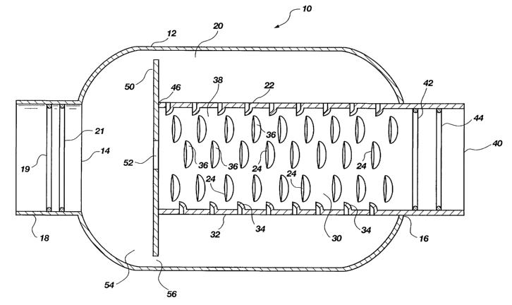
FIG. 1 is a cross-sectional side view of a first embodiment of an air turbine
device in accordance with the principles of the present invention;
FIG. 2 is a cross-sectional end view of an induction chamber of FIG. 1;
FIG. 3 is an end view of an airfoil of FIG. 1;
FIG. 4 is an end view of a vortex ring of FIG. 1;
FIG. 5 is a cross-sectional side view of the air turbine device of FIG. 1
illustrating the flow of air or gases through the device;
FIG. 6 is another cross-sectional side view of the air turbine device of FIG.
1 illustrating the flow of air or gases from the induction chamber into the
expansion chamber;
FIG. 7 is a cross-sectional side view of a second embodiment of an air
turbine device in accordance with the principles of the present invention
attached
to an exhaust system of a combustion engine;
CA 02438535 2003-08-15
WO 02/066799 PCT/US02/04452
-4-
FIG. 8 is a cross-sectional side view of a third embodiment of an air
turbine device in accordance with the principles of the present invention
attached
to an exhaust system of a combustion engine;
FIG. 9 is a cross-sectional side view of a fourth embodiment of an air
turbine device in accordance with the principles of the present invention;
FIG. 11 is a cross-sectional end view of an expansion chamber housing an
airfoil supported by a plurality of blades in accordance with the principles
of the
present invention; and
FIG. 12 is a cross-sectional side view of a fifth embodiment of an air
turbine device in accordance with the principles of the present invention.
DETAILED DESCRIPTION OF THE PREFERRED EMBODIMENTS
Referring to the drawings wherein like numerals indicate like elements
throughout, there is shown in FIG. 1 an air turbine device, generally
indicated at
10, in accordance with the preferred embodiment of the present invention. The
air turbine device 10 is comprised of an outer housing 12 having a generally
cylindrical shape. The housing 12 defines an inlet port 14 and an outlet port
16.
It should be noted that while the housing 12 has a cylindrical shape, those of
skill
in the art will appreciate that other geometrical shapes may be feasible. An
inlet
tube 18 is secured to the inlet port 14 for attachment of the air turbine
device 10
to an exhaust system of a vehicle (not shown). The inlet tube 18 is provided
with
a pair of vortex rings 19 and 21 to help form a vortexial flow of air through
the
air turbine device 10. The housing 12 defines an expansion chamber 20 which
extends from the inlet 14 to the outlet 16.
Housed within the housing 12 is an induction tube 22 which is fixedly
mounted to the outlet 16 of the housing 12. The induction tube 22 is comprised
of an elongate tubular member having a plurality of perforations 24 formed
therein. In the preferred embodiment, the perforations 24 are louvers which
extend into the induction chamber 30 formed by the tube 22. The louvers are
formed by stamping or cutting the exterior wall 32 of the tube 22 to force
portions 34 of the wall 32 into the interior of the tube 22. As shown in FIG.
2,
CA 02438535 2003-08-15
WO 02/066799 PCT/US02/04452
-5-
the louvers 36 are preferably formed in a helical pattern around the tube 22.
It is
also contemplated that one or more spiral or helical slits may be provided in
the
tube 22 to accomplish a similar effect. Thus, the terms louvers or
perforations
are intended to include such structure.
Referring again to FIG. 1, the louvers 36 extend around the interior
surface 38 of the tube 22 and face in a direction so as to encourage air
flowing
toward the outlet 40 of the tube to flow from the tube 22 into the expansion
chamber 20. A pair of vortex rings 42 and 44 are secured within the tube 22
proximate the outlet 40 of the tube 22. The vortex rings 42 and 44 provide a
slight amount of back pressure to the air turbine device, which is sometimes
necessary to the operation of some gas engines. In addition, the vortex rings
help
to maintain the vortexial flow of air as the air leaves the outlet 40.
Attached to the inlet 46 of the tube 22 is a disc-shaped member 50 which
extends across the expansion chamber proximate the inlet 14 of the housing 12.
The disc-shaped member 50 forms an airfoil in the path of the air flowing
through the housing 12. This airfoil 22 defines a central aperture 52 which is
in
fluid communication with the inner vortex chamber 30. In addition, the airfoil
22 has a diameter that is less than the diameter defined by the inner surface
54
of the housing 12. As such, air entering the inlet tube 18 can either flow
through
the aperture 52 or through the annular space 56 formed between the airfoil 50
and the inner surface 54 of the housing 12.
FIG. 3 illustrates a front view of the airfoil 50 shown in FIG. 1. The airfoil
50 is provided with the circular aperture 52 which is concentric with the
airfoil
50. The size of the airfoil 50 as well as the diameter of the aperture 52 is
dependent upon the flow of air from the exhaust of the combustion engine. The
size of the vortex expansion chamber, however, is dependent upon the diameter
of the inlet coupled thereto. The diameter of the expansion chamber is defined
by 1.5 times the inlet pipe diameter. The length of the expansion chamber to
accommodate the second harmonic resonance is 2.0 times the diameter of the
expansion chamber. The length of the expansion chamber to accommodate the
third harmonic resonance is 3.5 times the diameter of the expansion chamber.
CA 02438535 2003-08-15
WO 02/066799 PCT/US02/04452
-6-
For a six inch expansion chamber diameter, the outermost airfoil diameter is
approximately 5.4 inches and the diameter of the aperture or bore of the
airfoil is
approximately 1.6 inches. In order to create the desired vortex effect and
mixing
the air flows passing around and through the airfoil, the area of the annular
space between the airfoil and the expansion chamber and the area of the
aperture are sized to produce the most efficient flow of air through the
device. In
proportion, the ratio of air passing around the airfoil compared to the air
passing
through the airfoil for a six inch diameter expansion chamber is approximately
2.7 to 1.
FIG. 4 illustrates a vortex ring, such as vortex ring 19 shown in FIG. 1.
Similar to the dimensions of the airfoil 50, the size of the vortex ring 19 is
dependent upon the inner diameter of the inlet tube 18 to which the vortex
ring
19 is attached. The vortex ring 19 extends into the inlet tube to form a
slight
constriction but not enough to cause any appreciable restriction of flow
therethrough. Obviously, as shown in FIG. 1, the outer diameter of the vortex
ring 19 is defined by and thus equal to the inner diameter of the inlet tube
18.
Referring now to FIG. 5, the flow of exhaust 60 through the air turbine
device 10 is illustrated. As the flow of exhaust 60 enters the expansion
chamber
20, the air is directed either through 62 or around 64 and 66 the airfoil 50.
The
air passing around the airfoil 50 will necessarily be at a higher velocity
that the
air 62 that flows directly through the aperture 52. The faster moving air 64
and
66 will create a low pressure zone within the outer vortex or expansion
chamber
20.
The air 62 entering the inner vortex or induction chamber 30 will be at a
lower velocity than the air in the expansion chamber 20 and thus at a higher
pressure. As such, the air 71 within the induction ehamber 30 will be
encouraged to flow into the expansion chamber 20. As shown in FIG. 6, the flow
of air 70 from the induction chamber 30 to the expansion chamber 20 is further
assisted or encouraged by the louvers 36 formed into the tube 22.
Referring again to FIG. 5, to arrangement of the louvers 36 force the air 70
into a vortexial flow 72 around the tube 22. As this flow 72 reenters the
inner
CA 02438535 2003-08-15
WO 02/066799 PCT/US02/04452
_'J_
tube 22 in order to pass out through the exit or exhaust port 79 as
represented by
arrow 80, the inner flow 71 of air is also encouraged into a vortexial flow.
As
such, both the flow of air around the tube 22 and inside the tube 22 is
flowing in
a vortexial manner.
FIG. 7 illustrates another preferred embodiment of a tunable air turbine
device, generally indicated at 100, which includes the air turbine device 10
shown in FIG. 1. The air turbine device 10 has an opening 102 formed in the
housing to which a tunning chamber 104, preferably comprised of an elongate
tube, is attached. The tuning chamber 104 forms a second flow passage from the
air turbine device 10 but is linked to and in fluid communication with the
expansion chamber 20. The tuning chamber 104 reconnects and is in fluid
communication with an exhaust port 106 attached to the exit port 40 of the air
turbine device 10.
The amount of air 110 flowing through the tuning chamber 104 is
controlled by a valve 112, preferably an electronically controllable butterfly
valve, which can partially or totally restrict the flow of air 110 through the
tuning
chamber 104. The butter fly valve 112 may be powered by a 12 volt power
supply 114 and include a variably controllable open position gauge 116 and/or
an open/close controller 118. The resonant sound emanating through the tuning
chamber l04 will have had a lesser amount of high frequency noise cancelled by
the air turbine device. By controlling the amount of flow 110 through the
tuning
chamber 104, a user can effectively control the tone of the sound from the air
turbine device system 100.
As shown in FIG. 8, another preferred embodiment of an air turbine
device, generally indicated at 200, is adapted for use in marine applications.
An
air turbine device 202 having a configuration similar to that illustrated in
FIG. 1
is attached to an exhaust manifold 204. The exhaust flow diverter 204 includes
an exhaust inlet 206 which is coupled to the exhaust manifold (not shown) of
an
inboard boat motor. An actuator 208 controls a valve 210 housed within the
exhaust flow diverter 204. The valve 210 is preferably a butterfly valve which
can partially or totally obstruct the air flow into the air turbine device
202, as
CA 02438535 2003-08-15
WO 02/066799 PCT/US02/04452
_g_
controlled by a user. Similar to the butterfly valve illustrated with respect
to FIG.
7, the butter fly valve 208 may be powered by a 12 volt power supply 212 and
include a variably controllable open position gauge 216 and/or an open/close
controller 218. The air that is restricted by the butterfly valve 210 is
diverted
into the diverter outlet 220. The diverter outlet is coupled to the factory
stern
drive outlet (i.e., the exhaust outlet already existing on the marine vessel).
The exhaust flow diverter 204 is thus controllable to allow a portion or all
of the exhaust air flow entering the exhaust inlet of the diverter to flow
through
the air turbine device 202. As such, the outlet 222 of the diverter 204 is
coupled
to the inlet 224 of the air turbine device. The outlet 226 of the air turbine
device
202 is coupled or mounted to the hull 228 of the boat or marine vessel. The
outlet 226 is positioned above the water line 230 so that, unlike the factory
exhaust which uses the water to act as an air turbine device, the flow of
exhaust
out of the air turbine device 202 is not impeded by the back pressure that
would
otherwise be caused if the outlet 226 of the air turbine device 202 was
submerged. Such a free flowing air turbine device configuration increases
horse
power while providing a compact air turbine device that does not add
significant
weight or size to an existing vessel.
FIG. 9 illustrates another embodiment of an air turbine device, generally
indicated at 300 in accordance with the principles of the present invention.
Similar to other embodiments described herein, the air turbine 300 is
comprised
of an inlet 302, an expansion chamber outer housing 304 and an outlet 306. The
inlet 302 and outlet 306 are of similar diameter, with the housing 304 having
a
larger. diameter and interposed between the inlet and the outlet. A chop core
308 is positioned within expansion chamber and defines an induction chamber
310. The chop core 308 is provided with a plurality of louvers 312 that extend
into the induction chamber 310 and are arranged along the inner wall 314 of
the
chop core so as to encourage rotational flow of the air or exhaust gases
entering
the induction chamber out into the annular expansion chamber 316 defined
between chop core 308 and the expansion chamber outer housing 304. Thus, the
louvers may be spirally or helically configured around the chop core 308.
CA 02438535 2003-08-15
WO 02/066799 PCT/US02/04452
-9-
An airfoil 318 is positioned in the proximal end 320 of the housing 304
and is attached to the proximal end 322 of the chop core 308. The airfoil 318
has a frustoconical shape with a curved outer surface 320 and a longitudinally
extending central bore 322 extending from the proximal end 324 of the airfoil
318 to the distal end 326 and in fluid communication with the induction
chamber 310. The airfoil 318 may be comprised of a ceramic material, metal or
other heat resistant materials. The air foil 318 divides the air entering the
device
300 through the input 302 so that a portion of the air enters the induction
chamber 310 through the bore 322 while the remaining air flow enters the
induction chamber from the expansion chamber 316.
One important aspect of the invention is to cause the air flow through the
device to rotate into a vortex. The spinning air causes the air to flow more
efficiently the device 300. The air flow is first caused to rotate relative to
the
device 310 at the intake 302 by a pair of vortex convolutions 328 and 330 that
are formed into the intake portion 302 of the device 300. The vortex
convolutions 328 and 330 are each formed by bending, casting or otherwise
forming the intake 302 to form annular recesses 331, 332 and 333 in order to
form the interior annular recesses or convolutions 328 and 330. As the air
flow
encounters the convolutions 328 and 330 pass through the convolutions, the air
is caused to spin. The air continues to spin as it passes over and around the
airfoil 318. The perforations or louvers 312 are configured to cause rotation
of
the air flow counter to the rotation caused by the convolutions 320 and 328 as
the air is drawn by the convolutions from the induction chamber to the
expansion
chamber 316 through the louvers 312. This mixing of the air flow in the
expansion chamber and induction chamber causes turbulence in the air flow.
The result of such turbulence is a cancellation of noise otherwise present in
the
exhaust flow.
This turbulent flow then recombines in the outlet 306 and is again caused
to spin into a vortex as it passes through a second set of convolutions 336
and
338 formed in the outlet 306 in a similar manner.to the convolutions 328 and
CA 02438535 2003-08-15
WO 02/066799 PCT/US02/04452
-10-
330 formed in the intake 302. Such a vortex at the outlet 306 again encourages
the flow of air out of the device 300.
The length of the expansion chamber 304 also has an effect on the noise
cancellation ability of the device 300. That is, the length of the device 300
can
be tuned to cancel out various noise frequencies including multiple harmonics.
That is, by tuning the length of the device 300 to match the frequencies
generated by a particular engine, the first, second and third harmonics can be
dampened producing a more quiet running engine. Referring now to FIG. 10
is shown another embodiment of an air turbine device, generally indicated at
400, in accordance with the principles of the present invention. The device is
comprised of an intake 402, an expansion chamber housing 404 defining an
expansion chamber 405 and an exhaust port 406. Positioned within the
expansion chamber 405 is an airfoil 408 that defines a longitudinally
extending
bore 4I2 and divides the air into a portion that flows around the air foil and
a
portion that flows through the air foil. A pair of airfoil convolutions 414
and 416
are provided in the bore 412 of the airfoil 408 to encourage vortex flow of
the air
through the airfoil and into the expansion chamber 405.
The airfoil 408 is concentrically centered within the expansion chamber
405 and held relative thereto with a plurality of vanes or blades 418 and 420.
There may be two, three, four or more of the blades 418 and 420. The blades
418 and 420 as shown are configured to be spirally or helieslly oriented
around
the outer surface 422 of the airfoil 408 so as to cause rotation of the air
flowing
around the airfoil. The orientation of the blades 418 and 420 is such that the
air
flowing around the air foil 408 is counter rotated to the air flowing through
the
bore 412. As the air recombines in the expansion chamber 405, counter spinning
air flows cause turbulence therein between so as to cause cancellation of
noise
from the engine to produce a muffling effect while allowing essentially the
free
flow of exhaust gases through the device 400. The air then recombines in the
expansion chamber 405 and exits through the exhaust port 406 with the
convolutions 424 and 426 causing the air to spin in a vortex as it exits the
device
400.
CA 02438535 2003-08-15
WO 02/066799 PCT/US02/04452
-11-
FIG. 11 shows a cross-sectional end view of an expansion chamber
housing 500 with blades 501, 502, 503 and 504 supporting an airfoil cone 506.
The blades 501-504 are attached to the inner surface 508 of the housing 500
and
to the outer surface 510 of the airfoil cone 506 so as to cause rotation of
the air
flow passing around the airfoil cone 506 in the direction of the blades 50-
504. It
is desirable to orient the blades 501-504 so that the air flowing over the
airfoil
cone 5I0 is spinning in a direction opposite to the rotation of the air
flowing
through the internal passageway 512 extending through the airfoil cone 506.
Finally, as shown in FIG. 12, the principles of the present invention may
be applied to the intake of a combustion engine as well. An intake air turbine
600 is comprised of an intake port 602, an expansion chamber housing 604 and
an exhaust port 606. Housed within the expansion chamber housing 604 is an
airfoil 608 that divides the air flow similar to that shown in the other
embodiments herein. The intake port 602 is provided with vortex convolutions
610 and 612 that cause the air flow to rotate relative thereto. As an intake
device, the flow of air from the intake port 602 to the exhaust port 606 is
encouraged to rotate throughout the device. That is the air flowing through
the
expansion chamber, both around and through the bore 620 of the airfoil, is
rotated in the same direction so as to increase the flow of air through the
exhaust
port 606 and into the intake manifold (not shown) of a combustion engine. The
blades 616 and 618 that support the airfoil 608 within the housing 604 are
helically oriented around the airfoil to encourage this consistent rotational
flow
of air around the airfoil so as to minimize turbulence as the air flow
recombines
in the expansion chamber 622. In the event of any such turbulence, the exhaust
port vortex convolutions 624 and 626 encourage continued and uniform vortex
rotation of the air flow.
Various tests have been conducted using an air turbine device in
accordance with the principle invention with surprising results. An air
turbine
device was installed on a Kenworth 525 CAT Cummins N14 diesel engine in a
muffler configuration. That is, the air turbine device was installed on the
exhaust
in replacement of a stock muffler. The average gas mileage of the engine using
CA 02438535 2003-08-15
WO 02/066799 PCT/US02/04452
-12-
the stock muffler was 5.7 MPG. After installation of an air turbine muffler in
accordance with the present invention with no other modification to the engine
the following results compiled in TABLE I were achieved.
TABLE I
(Test results for Kenworth 525 CAT Cummins N14 diesel engine)
MILES FUEL USED (gal.) FUEL %GAIN
TRAVELED MILEAGE
979 148 6.61 15.96
941 150 6.20 8.77
1242 208 5.97 4.74
1194 I88 6.35 l I.4
1134 218 6.11 7.19
1007 166 6.06 6.32
1600 257 6.22 9.12
1275 205 6.24 9.47
1063 175 6.00 5.56
1071 170 6.29 6.61
880 140 6.28 10.35
1140 180 6.30 10.53
2035 311 6.54 14.74
1980 319 6.20 8.77
1334 213 6.26 9.82
1124 2 75 6.40 12.28
1401 225 6.20 8.77
1958 314 6.20 8.77
Based on the foregoing test results, the average fuel mileage was 6.25 MPG
with
an average percent gain of 9.4 percent.
CA 02438535 2003-08-15
WO 02/066799 PCT/US02/04452
-13-
A field test of a 2000 Ford Excursion powered by a 7.3 liter turbo charged
Powerstroke diesel engine. The Excursion had 32,551 miles on the odometer
when the test began with the test running for approximately 5,000 miles of
driving. An air turbine device in accordance with the present invention was
installed as a muffler on the exhaust of the engine replacing the stock
muffler.
The original equipment mileage was approximately 14.54 miles per gallon based
upon a 6,152 mile cross-country filed test from Boise, Idaho to Denver,
Colorado
to Milwaukee, Wisconsin to Nashville, Tennessee to Birmingham, Alabama and
returning to Boise, Idaho.
After installation of the air turbine muffler of the present invention, the
Excursion was driven from Salt Lake City, Utah to Boise, Idaho, to Portland
Oregon, to Seattle, Washing to Bellingham, Washington , back to Seattle
Washing then to Yakima, Washington. During the trip, the excursion averaged
15.97 miles per gallon. Subsequent to the above trip, the Excursion was driven
3901 miles from Salt Lake City to Rochester, New York and back. This cross-
country trip yielded an average of 16.59 miles per gallon.
In addition to the increase in gas mileage, the engine runs cooler with the
air turbine installed and exhibits increased horse power, especially
noticeable on
uphill climbs and passing situations at highway speeds. Furthermore, the sound
level of the exhaust is exceptional. In fact, the sound dampening aspects
result in
the muffling of the typical "diesel-type" engine noise not achieved by
standard
mufflers.
While the apparatus of the present invention has been described with
reference to certain preferred embodiments to illustrate what is believed to
be the
best mode of the invention, it is contemplated that upon review of the present
invention, those of skill in the art will appreciate that various
modifications and
combinations may be made to the present embodiments without departing from
the spirit and scope of the invention as recited in the claims. The claims
provided
herein are intended to cover such modifications and combinations and all
equivalents thereof. Reference herein to specifie details of the illustrated
embodiments is by way of example and not by way of limitation.