Note: Descriptions are shown in the official language in which they were submitted.
CA 02438613 2010-04-19
-1-
AMALGAM-DOPED MERCURY LOW-PRESSURE UV IRRADIATOR
The present invention concerns an amalgam mercury low pressure UV lamp. Such
lamps are
in operational use. They are used in the disinfection of water and waste water
and are
superior because of their especially high efficiency. This high efficiency is
achieved by
binding the mercury into an amalgam (preferably indium) in a lamp with low
internal
pressure. This mercury is released in the gas phase when the lamp reaches an
operation
temperature of some 90 C. The decisive factor for this operating temperature
is the
temperature of the amalgam.
Other types of UV lamps are those low pressure lamps not equipped with
amalgam, whose
optimal operating temperature is in the region of about 40 C, with these lamps
displaying a
lesser efficiency, and medium pressure UV lamps which display an internal
pressure of some
1,000 mbar and have an operating temperature of several hundred degrees
Celsius. These
lamps do have a relatively high output in the kilowatt area. But the
efficiency, thus the ratio
between radiation output in the desired wavelength range and electrical power
consumption,
is lower than the efficiency of the amalgam mercury low pressure UV lamp found
here.
In order to reach the aforementioned optimal temperature of some 90 C in
operation, generic
UV lamps are not immersed directly into the liquid to be disinfected. The
temperatures
prevailing there in the drinking water or waste water domain are too low to
maintain the
necessary temperature of the UV lamp. Therefore they are sheathed in cladding
tubes, which
delimit an air gap between their inner wall and the outside of the UV lamp.
The low thermal
conductivity of air guarantees, in the operation of the UV lamp, that the
latter will not cool
down to below 90 C. But the basic requirement is a sufficiently high
electrical power.
It is apparent from these boundary conditions that generic UV lamps when
operated in a
cladding tube can only be adjusted to a limited extent. So for example in ex-
factory UV
lamps, which display an especially high initial UV yield, the electrical power
cannot be
reduced so far that the radiated UV intensity is reduced to the level released
later on when the
UV lamp is older. The UV lamp then becomes too cold, which reduces the
radiation yield.
In another case, the operating condition may arise where the water to be
treated is at a
CA 02438613 2010-04-19
-2-
relatively high temperature, for example 60 C. If relatively old UV lamps are
used in these
operating conditions, a high level of electrical power must be supplied to
them in order to
provide the necessary UV intensity. The result of the high ambient temperature
is that the UV
lamp is not cooled to the optimal operating range, as occurs at lower
temperatures. The
efficiency of the UV lamp falls, because the temperature of the UV lamp
settles to over 90 C.
This operating condition is not desirable.
It is therefore the task of the present invention to improve an amalgam
mercury low pressure
UV lamp in such a way that it can be operated independently of the water
temperature and
preferably with variable UV output.
In accordance with the present invention, there is provided a UV lamp unit,
comprising: a
lamp in the form of a mercury low pressure amalgam lamp that is provided with
at least one
amalgam deposit; a cladding tube that surrounds said lamp in such a way that
an air gap is
provided between said lamp and said cladding tube, and; means provided in an
axial direction
of said lamp, in the region of said at least one amalgam deposit, for
influencing the
temperature of the amalgam, wherein an electrical heating element is disposed
on the outside
of said lamp in the vicinity of the amalgam.
In accordance with another aspect of the present invention, there is provided
a UV lamp unit,
comprising: a lamp in the form of a mercury low pressure amalgam lamp that is
provided
with at least one amalgam deposit; a cladding tube that surrounds said lamp in
such a way
that an air gap is provided between said lamp and said cladding tube, and;
means provided in
an axial direction of said lamp, in the region of said at least one amalgam
deposit, for
influencing the temperature of the amalgam, wherein said means for influencing
said
temperature of the amalgam is a band of metallic material disposed between
said lamp and
said cladding tube, wherein said band is secured to said lamp in the area of
the amalgam, and
wherein said band has an area that is radially movable relative to said lamp.
Because in the axial line of the UV lamp, at the axial position of the amalgam
deposit, a
means of influencing the temperature of the amalgam is provided, if the
amalgam
temperatures are low, the temperature can be raised. Preferably the
CA 02438613 2003-08-15
-3-
means of influencing the temperature is also designed such that the
temperature of
the amalgam can also be lowered, if this should be too high with respect to
the
optimal operating range.
A preferred design of the invention inserts a metallic band between the lamp
and
the cladding tube. The band preferably extends in the direction of the
periphery
of the UV lamp to the axial position of the amalgam. This band can, according
to
a refinement of the invention, be made at least partly from bimetal, so that
the
spatial arrangement alters as a function of temperature. If the band is fixed
in the
area of the amalgam to the UV lamp and an area is provided which moves
radially
with respect to the UV lamp, said area being able to attach itself to the
inside of
the cladding tube, the band can also be used to disperse heat from the area of
the
amalgam, thus allowing cooling.
Another design for this invention provides an electrical heater element
arranged
on the outside of the UV lamp in the area of the amalgam. This heater element
can be in the form of an ohmic resistor or PTC resistor. For preference, the
resistor abuts on the outside of the UV lamp in the area of the amalgam and on
the
inside of the cladding tube, so that without admitting electrical current to
the
heater element, heat can be transferred from the lamp to the cladding tube and
in
this way the amalgam can be cooled. An especially simple wiring of the heater
element is possible, if this heater element is connected in parallel to a
spiral-
wound filament of the lamp. The heater can then be switched on using the
heating
current for the heating filament. It is also possible to connect the
electrical heater
element in parallel to the connections of the UV lamp so that the heater works
as a
function of the operating voltage of the UV lamp.
Three examples of designs for this invention are described below with the aid
of
the drawing.
CA 02438613 2010-04-19
-4-
These show:
Figure 1: A UV lamp according to invention with a band-shaped means of
influencing
temperature in a lateral view;
Figure 2a, 2b: the UV lamp according to Fig. 1 in an axial cross section in
the area of the
amalgam;
Figure 3: a UV lamp with an electrical heating means; and
Figure 4: a UV lamp with an electrical heating means wherein the heating
voltage of the
electrical heating means is tapped from the voltage applied between the
diametrically opposed spiral-wound filaments.
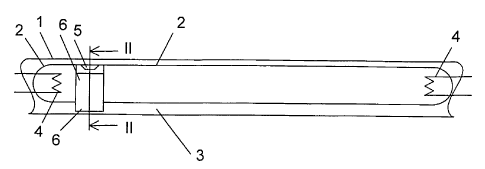
In Figure 1, a UV lamp unit according to invention is shown in a lateral view.
The lamp unit
displays an external cladding tube 1 which surrounds a UV lamp 2 in the form
of an amalgam
mercury low pressure UV lamp. Between the cladding tube 1 and the UV lamp 2
there is an
air gap 3. The UV lamp 2 displays, in a standard way, spiral-wound filaments 4
which can be .
powered to start and maintain the gas discharge with an incandescent voltage
and an
operating voltage respectively. At an axial distance from the left spiral-
wound filament 4 an
amalgam deposit is provided which, again in a standard way, can consist, for
example, of an
indium-mercury amalgam. This amalgam is particularly highly efficient in
operating the
UV lamp.
A metal coil 6, which slightly surpasses the axial extension of the amalgam
deposit 5, is fixed
in the area of the amalgam deposit 5 externally on the UV lamp 2 and lies in
the air gap 3
between the cladding tube 1 and the UV lamp 2.
The more precise structure in the area of the line II-II is shown in more
detail in Figures 2a
and 2b, which show a cross section through the lamp unit according to Figure 1
along this
line.
Figure 2a shows the lamp unit with the cladding tube 1, which is surrounded
here by the
liquid to be disinfected 10, at low operating temperature. The coil 6 is
connected at 11 to the
exterior of the UV lamp 2 so as to conduct heat, for
i
CA 02438613 2003-08-15
-5-
example pasted on there with a UV-resistant adhesive. Starting from position
11,
the coil 6 runs as far as its free end roughly parallel to the circumferential
line of
the UV lamp 2. In this example of design the coil 6 is made from bimetal and
because of the low temperatures is in a spatial design which corresponds
roughly
to the perimeter of the UV lamp 2. So it abuts closely against the UV lamp up
to
its free end.
In Figure 2b the configuration according to Figure 2a is shown at a higher
operating temperature. The coil 6 expands due to the effect of the
temperature,
with the fastening at position 11 holding the coil 6 there firmly. The free
end of
the coil 6 approaches the cladding tube 1. In the intermediate area, the coil
6 is
raised from the surface of the UV lamp 2.
In operation the lamp unit described thus works as follows:
Firstly the UV lamp 2 is ignited in the accepted way such that the gas
discharge
develops in the interior of the UV lamp 2. As the result of the gas discharge
the
UV lamp 2 heats up. The heat produced in the UV lamp 2 is dispersed via the
air
gap to the cladding tube 1 and there released into the liquid 10, so that the
temperature within the UV lamp rises from the start, until it attains a state
of
equilibrium. When the liquid to be disinfected 10 is at low temperatures,
which
sometimes occur in the waste water and drinking water domain, the condition
may arise that the equilibrium temperature in the UV lamp 2 is not sufficient
to
bring the amalgam in the amalgam deposit 5 to the optimal operating
temperature,
which is in the region of 90 - 95 C. In these cases, the coil 6, which
closely
abuts against the UV lamp 2 as in Figure 2a, reflects the radiation output to
the
axial position of the amalgam deposit 5 into the interior of the UV lamp 2 so
that
at this point the temperature in the UV lamp rises. The coil 6 also absorbs
the
heat emanating from the UV lamp. In addition the coil heats up as the result
of
absorbed radiation flux from the UV lamp 2. The coil 6 is heated up and
transfers
this heat via the thermally conductive connection at position 11 to the
amalgam
CA 02438613 2003-08-15
-6-
deposit 5, so that the latter at first heats up more rapidly in the start
phase, so that
the UV lamp 2 reaches its operating temperature and thus its excellent
efficiency
more quickly in comparison to the usual arrangements. In operation the coil 6,
at
low temperatures of the liquid 10, prevents a drop to below the operating
temperature of the UV lamp 2 and thus in turn ensures lasting good efficiency.
Furthermore, if the operating conditions allow, the electrical power supplied
to
the UV lamp 2 can be reduced. This reduction of the electrical power can for
example be desired if the flow rate of the liquid to be disinfected 10 is low
and
therefore a low UV intensity will result in adequate disinfection. The reduced
electrical power leads to a reduction of the equilibrium temperature in the
interior
of the UV lamp 2. This drop in temperature counteracts the effect of the coil
6,
described above, on the amalgam deposit 5.
Figure 2b shows the UV lamp according to Figure 2a under operating conditions
at higher temperature. The coil 6 has expanded because of its bimetallic
properties. In the air gap 3 it approaches the cladding tube 1 more closely or
can
abut on the cladding tube if the temperature continues to rise. In this way
the coil
6 conducts away heat which is absorbed in the area of the thermally conductive
connection at 11 from the amalgam deposit 5, to the cooler cladding tube wall
of
the cladding tube 1. In this way, the amalgam deposit 5 is cooled so that at
electrical power or at a high temperature of the liquid 10 the temperature of
the
amalgam deposit 5 does not increase excessively. Thus the coil 6 can
counteract
any heating of the amalgam deposit 5 beyond the range of the optimal operating
temperature. This guarantees that the operating temperature, which assures a
good efficiency, is maintained.
In addition to the design shown in Figures 1 and 2 with a bimetallic coil,
other
mechanical solutions are also possible, such as e.g. devices which exploit
specific
characteristics of what are known as shape memory metals. So it is also
possible
e.g. to arrange a screen between the amalgam deposit 5 and the cladding tube 1
which is displaced depending on the temperature in radial direction or axial
CA 02438613 2003-08-15
-7-
direction of the UV lamp 2 and thus adjusts the temperature of the amalgam
deposit 5. It is also possible to arrange a radiation reflector on the side of
the UV
lamp 2 diametrically opposite the amalgam deposit 5, which reflects back only
the
radiation output occurring there to the amalgam deposit 5 and which if
necessary
alters its reflective properties as a function of temperature.
Another design of this invention is shown in Figures 3 and 4. This design does
not
provide a mechanical device to influence the temperature of the amalgam
deposit
5, but an electrical heating device 12. The heating device 12 is fastened as a
heat
conductor on the exterior of the UV lamp 2 in the area of the amalgam deposit
5.
It can for example consist of a simple heating resistor, a PTC (positive
temperature coefficient) resistor or a VDR (voltage-dependent resistor). The
heating element 12 in Figure 3 is connected via connecting lines 13 and 14
parallel to the spiral-wound filaments 4 so that when the heating voltage for
the
spiral-wound filaments 4 is switched on, there is also a heating voltage for
the
heating element 12. In this way, the amalgam in the amalgam deposit 5 is
heated
right from the starting procedure. This allows the operating temperature to be
reached more quickly. If the electrical power supplied is reduced, the heating
voltage can then be switched on again, in order to prevent the UV lamp cooling
off. Preferably, the heating element 12 with its thermally conducting exterior
abuts on the cladding tube 1, so that without being supplied with heating
voltage,
the heating element 12, due to its own thermal conductivity, can disperse heat
from the amalgam deposit 5 to the cladding tube and thus contribute to a
reduction in the operating temperature, if the temperature in the UV lamp 2
rises
above the optimal range.
In Figure 4, the lamp unit is again provided with a heating resistor 12 as
described
above. The connections 13 and 15 are however laid out in Figure 4 in such a
way
that the heating voltage of the heating element 12 is tapped from the voltage
applied between the diametrically opposed spiral-wound filaments 4. The
heating
voltage 12 is thus obtained from the operating voltage of the UV lamp.
CA 02438613 2003-08-15
-8-
This configuration can be used when the UV lamp is controlled in operation via
the current, thus for example is operated with constant current. Depending on
the
operational con and especially depending on the temperature in the UV lamp,
the
voltage applied at the UV lamp will then adjust itself. In that case a high
lamp
voltage is an indication of too low a temperature of the amalgam deposit 5. In
the
circuit shown in Figure 4, if the UV lamp voltage were to rise above a defined
value, the heating in the heating element 12, which is designed here by way of
example as a VDR, would increase. The temperature in the amalgam deposit 5,
because of the heat output fed in, would also rise, so that the operational
voltage
falls again. Gradually, a controlled equilibrium will develop which, when the
heating resistor 12 is suitably designed, lies in the range of the optimal
operating
temperature. Also, in this configuration, without the heating element 12 being
supplied with heating voltage, any excessive heat from the amalgam deposit 5
can
be released to the cladding tube 1, so that when there is higher output or
higher
outside temperature the amalgam deposit 5 is cooled.