Note: Descriptions are shown in the official language in which they were submitted.
CA 02439369 2003-08-26
WO 02/071656 PCT/GB02/00674
2 WIRELESS L1UPLEX OPTICAL COMMUNICATION SYSTEM
2
3 The invention relates to wireless optical
4 communication systems and can be used in digital
communication systems, in particular for wireless
6 information exchange, e.g. between computers that
7 are moving in relation to each other, or are divided
8 by a barrier impeding the use of wireless
9 communication means.
11 An optical communication system is known, which uses
12 two terminals located on the ends of an optical
13 communication line formed thereby. Each terminal
14 includes a combination of laser transmitters, which
emit a set of laser beams carrying information
16 signals received at the other terminal which are
17 summed up incoherently. However such systems must
18 use laser transmitters in order to operate for long
19 periods, these are expensive and technically
complex.
21
CA 02439369 2003-08-26
WO 02/071656 PCT/GB02/00674
2
1 An optical communication system is known, which
2 provides for wireless information exchange and
3 contains the transmitting and receiving components
4 made in the form of an optical transmitter and an
optical receiver. The problem with this known system
6 is that environmental conditions influence the
7 stability of communication, when high rates of
8 information transmission, and long range
9 communication are required. In addition such
optical communication systems have a short service
11 life with rather high production and operation
12 costs.
13
14 Among the environmental conditions that degrade
communication there are:
16
17 1. Atmospheric phenomena, such as fog, rain, snow.
18 These conditions lead to attenuation of the
19 signal in the communication line.
2. Deformations and slow vibrations of buildings
21 and structures, where optical receivers and
22 optical transmitters (emitters) are installed.
23 These result in a loss or partial reduction of
24 the received signal level due to broken mutual
pointing of the optical receivers and optical
26 transmitters (emitters) at the opposite
27 communication points.
28 3. Crossing of the communication lines by non-
29 transparent objects, e.g. birds, which can
bring about sharp short-time weakening of the
31 signal.
CA 02439369 2003-08-26
WO 02/071656 PCT/GB02/00674
3
1 4. Position error and change of the angle at which
2 the beam arrives at the optical receiver
3 aperture.
4 5. When the beam passes through convection
currents caused by heat from the sun, for
6 example, fluctuations of the light capacity on
7 the photodiode of the optical receiver can
8 result causing poor communication quality
9 where large beam amplitudes are required.
11 The present invention is at least in part aimed at
12 minimising the communication quality reduction that
13 result from the above factors as well as providing a
14 system that is cheap to produce and run.
16 Tn accordance with the present invention there is
17 provided apparatus for wireless duplex
18 communication, comprising, a first optical
19 transceiver having a first optical transmitter and a
first optical receiver, a second optical transceiver
22 having a first optical transmitter and a first
22 optical receiver, the first and second optical
23 transceivers being located at the opposite end of an
24 optical communication line formed thereby, wherein
the output of each of the optical transmitters is a
26 diverging beam of incoherent electromagnetic
27 radiation arranged to have a cross sectional
28 diameter which is larger than the cross sectional
29 diameter of the respective optical receiver at that
point on the communication line at which the
31 respective optical receiver is situated.
CA 02439369 2003-08-26
WO 02/071656 PCT/GB02/00674
4
1 Preferably, the optical transmitter emits
2 electromagnetic radiation having a range of
3 wavelengths.
4 Preferably, the optical transmitter emits radiation
in'the range 800 to 900 nanometres.
6 Preferably, the optical transmitter comprises a
7 light emitting diode which provides the diverging
8 beam of incoherent electromagnetic radiation.
9 Preferably, the optical transmitter comprises the
LED and further comprises at least one optical
11 condenser lens, the input to the optical condenser
12 lens being provided by the LED and the output of the
13 optical transmitter being provided by the optical
14 condenser.
Preferably, the optical receiver consists of an
16 optical condenser lens, diaphragm and photodiode,
17 wherein the diaphragm is installed in the focal
18 plane of the optical condenser lens.
19 Preferably the distance O between the photodiode and
the diaphragm situated in the focal plane of the
21 optical condenser lens is defined by the formula
22 0 = b F / De, where
23 b - diameter of the light-sensitive site of the
24 photodiode,
Dc - diameter of the optical condenser lens.
26
27 Preferably, the input of the optical condenser is
28 the input of the optical receiver, and the output of
CA 02439369 2003-08-26
WO 02/071656 PCT/GB02/00674
1 the photodiode is the output of the first optical
2 receiver.
3
4 Preferably the beam angle 8 characterizing of the
5 first optical transmitter and the first optical
receiver of each of the said transceivers is defined
? from the following condition:
8 Tan2A = a / F, where
9 , a - diameter of the diaphragm aperture;
F - focal distance of the optical condenser measured
11 from the lens of the optical condenser to the centre
12 of the stop aperture.
13 Preferably, the beam angle is between 30 and 60
14 angular minutes.
Preferably, the distancebetween the optical
16 transmitter and optical receiver of a transceiver
is
17 greater than or equal d/2, where d = 30cm.
to
18 Optionally d=60cm.
I9 Preferably an input of the optical transmitter of
the first transceiver is connected to an output of a
21 converter through a modulator, and an output of the
22 optical receiver of the first transceivers is
23 connected to an input of a demodulator, the output
24 thereof being connected to an input of a converter.
Preferably, an input of the optical transmitter of
26 the second transceiver is connected to an output of
27 a converter through a modulator, and an output of
28 the optical receiver of the second transceivers is
CA 02439369 2003-08-26
WO 02/071656 PCT/GB02/00674
6
1 connected to an input of a demodulators, the output
2 thereof being connected to the input of a converter.
3
4 Preferably, the converter is made in the form of a
transformer, which transforms the signals of the
6 input discrete information into a coded signal using
7 the Manchester code during transmission, and which
8 is capable of a reverse transformation of signals
9 coming from the outputs of the respective
demodulators during reception.
11 Preferably, each optical transceiver further
12 comprises a second optical transmitter and a second
13 optical receiver.
14 Preferably, said transceivers are connected to the
input of the respective demodulators through a
16 summator.
17 Preferably, the input of the second optical
18 transmitter of each of the transceivers is connected
19 to the output of the respective modulator, and the
outputs of the first and second optical receivers is
21 connected to the input of the respective demodulator
22 through a summator.
23
24 In one embodiment of the present invention, the
optical system is a two-element system, which uses
26 one optical transmitter (optical emitter) and one
27 optical receiver in each optical transceiver thereby
28 forming two communication channels. When a two-
29 element optical transceiver is used, the spacing of
the optical transmitter and the optical receiver
CA 02439369 2003-08-26
WO 02/071656 PCT/GB02/00674
7
1 creates its own route of beam transmission for each
2 beam of the duplex wireless optical communication
3 line and therefore creates two communication
4 channels. The probability of simultaneous emergence
of conditions for maximum deviation of the beam in
6 both transmission directions and thus the
7 probability of simultaneous communication failure in
8 both channels, is reduced as compared to the case of
9 transmission along a single, common route.
11 In another embodirilent of the present invention, the
12 optical system is a four-element system. In this
13 case, each of the said transceivers is equipped with
14 a second optical transmitter and a second optical
receiver similar to the first optical transmitter
16 and the first optical receiver, which will together
17 form four communication channels. In this
18 embodiment, the optical transmitters and receivers
19 of each transceiver are spaced on a plane
perpendicular to their optical axes in relation to
21 the straight line connecting their optical axes on
22 the plane.
23
24 The optical transmitters and receivers of the first
transceiver are arranged in the following order:
26 first optical receiver;
27 first optical transmitter;
28 second optical receiver; and
29 second optical transmitter.
CA 02439369 2003-08-26
WO 02/071656 PCT/GB02/00674
8
1 In the second transceiver in relation to the first
2 transceiver, the optical transmitters and receivers
3 are arranged in the following order:
4 first optical transmitter;
first optical receiver;
6 second optical transmitter; and
7 second optical receiver.
8
9 It will be appreciated that the order of the first
and the second transceivers could be reversed.
11
12 The spacing between each component of each
13 transceiver is defined as being d/2, where d = 30cm.
14 It has been found that this value represents a value
below which the probability of protection against
16 ~ failures in the system reduces in cases where the
17 line of sight between the transmitter and receiver
18 is obscured by non-transparent objects or where
19 errors in the angle of arrival of the light beam to
the optical receiver have occurred or where the bean
21 passes through turbulent atmosphere.
22
23 The outputs of the photodiodes of the first and
24 second optical receivers of each of the said
transceivers are connected to the input of the
26 respective demodulator through a summator. The
27 outputs of the second optical transmitter in each of
28 the said transceivers are connected to the relevant
29 modulator.
CA 02439369 2003-08-26
WO 02/071656 PCT/GB02/00674
9
1 The invention will now be described by way of
2 example only with reference to the accompanying
3 drawings in which:
4
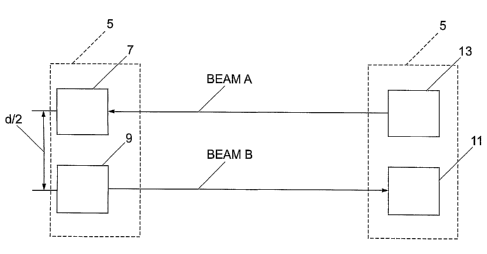
Fig. 1 shows a first embodiment of the present
6 invention having a pair of two-element transceivers
7 Fig. 1 also shows the location (spacing) of the
8 optical transmitters (optical emitters) and the
9 optical receivers of the transceivers as well as the
transmission geometry of optical beams emitted by
11 the optical transmitters;
12 .
13 Fig. 2 shows a second embodiment of the present
14 invention having two four-element transceivers, the
location (spacing) of the optical transmitters
16 (optical emitters) and the optical receivers in the
17 optical communication system is also shown along
18 with the transmission geometry of optical beams
19 emitted by the optical transmitters;
21 Fig. 3 is a flow chart of the optical communication
22 system for two-element transceivers of Fig. 1;
23
24 Fig. 4 is a flow chart of the optical communication
system for four-element transceivers of Fig 2; and
26
27 Fig. 5 shows an optical receiver (location of the
28 optical receiver elements) used in the embodiment of
29 the present invention illustrated in Figs. 1 to 4.
31 Referring to Figs. 1 and 3, the wireless optical
32 duplex communication system uses two-element
CA 02439369 2003-08-26
WO 02/071656 PCT/GB02/00674
1 transceivers each of which are connected to an
2 optical transceiver 3 and 5, a modulator 23 and 25,
3 a demodulator 27 and 29 and a converter 39 and 41.
4 The combination of optical transceiver, modulator,
5 demodulator and converter is referred to as a semi-
6 set. The first 3 and second 5 optical transceivers
7 are located facing each other at the opposite ends
8 of the optical communication line formed
9 therebetween. The converters 39 and 41 are connected
10 to the digital information exchange network
11 (transmission and reception) (not shown). Since the
12 system is duplex, and the operations of information
13 transmission and reception from one semi-set to the
14 other are the same in both directions, the
information transmission process will be explained
16 with reference to the communication line (channel)
17 from the first semi-set to the second with two-
18 element transceivers 3 and 5. The input information
19 (input discrete signal) comes to a converter 39 of
the first semi-set connected to the first optical
21 transceiver 3, where it is coded utilising
22 Manchester-type code. The input information is then
23 fed at pre-defined logical levels to Modulator 23
24 which controls the emission of LED 43a which is part
of the optical transmitter (optical emitter) 9 in
26 such a way~that during transmission of logical "1"
27 light pulses are emitted in the first half of the
28 given clock interval, and during transmission of
29 logical "0" light pulses~are transmitted in the
second half of the given clock interval. The signal
31 emitted by LED 43a comes to optical condenser 37a of
32 the first optical transmitter 9. The optical
CA 02439369 2003-08-26
WO 02/071656 PCT/GB02/00674
11
1 condenser 37a forms the beam angle of the optical
2 transmitter 9(optical emitter) to be between 30 and
3 60 angular minutes. In this example, the LED emits
~4 infra-red radiation containing a range of
wavelengths typically between 820 and 870 nm. The
6 radiation absorption characteristics in the
7 transmission path of the optical emitter vary
8 depending on atmospheric conditions. The use of a
9 radiation emitter that emits a range of wavelengths
ensures that at least some of the radiation reaches
11 the receiver without being absorbed by the
12 atmosphere irrespective of the atmospheric
13 conditions. In other examples of the present
14 invention, larger wavelength ranges can be used in
the infra-red region or other parts of the
16 electromagnetic spectrum.
17
18 Manchester-type coding is used, because it ensures
19 resistance to impulse noise and reduces the
probability of false alarms at the signal/noise
21 ratios found in devices of this type. In the
22 Manchester-type code the leading edge of the signal,
23 is used for coding unities and zeros. During such
24 coding, the bit period (time to transmit one bit of
data) is divided into two parts. Information is
26 coded by potential differences happening in the
27 middle of each bit period. A unity is coded by a
28 change from the low level to the high one, and zero
29 by the reverse change. At the beginning of each bit
period, there may be a service signal drop, if
31 ~ several unities or zeros are to be transmitted.
32 Since the signal is changed at least once per bit
CA 02439369 2003-08-26
WO 02/071656 PCT/GB02/00674
12
1 period such a code possesses good self-synchronizing
2 qualities and advantageously, allows the use of two
3 signal levels for data transmission.
4
The optical radiation of the first optical
6 transmitter 9 of the first transceiver 3 irradiates
7 the optical condenser 37c of the first optical
8 receiver 15 of the second transceiver 5, see beam A
9 in Fig. 1). The optical energy collected by the
optical condenser 37c of the first optical receiver
11 13 of the second transceiver 5 is directed through a
12 stop or diaphragm aperture 45 (Fig.5) to a
13 photodiode 35a. Thereafter, it is transformed into
14 an electric signal, and then directed to demodulator
29. The optical condenser of the optical receiver 35
16 forms an angular beam of between 30 and 60 angular
17 ~ minutes. In the demodulator 29 of the second
18 transceiver 5 the signal is transformed into logical
19 levels of the Manchester-type code and is fed to
converter 41 where it is transformed into an
21 information signal in accordance with the
22 requirements of the network protocols and directed
23 to the information transmission digital network.
24
To reduce the probability of communication failures
26 in case communication lines are crossed by non-
27 transparent objects, the optical receiver and
28 optical transmitter of each semi-set are spaced
29 apart on a plane perpendicular to their optical axes
to a distance of d/2 where d = 30 cm. This reduces
31 the probability of simultaneous failure in both
32 channels of the duplex communication line.
CA 02439369 2003-08-26
WO 02/071656 PCT/GB02/00674
13
1
2 When a two-element optical transceiver, as described
3 with reference to Figs. 1 and 3, is used, the
4 spacing~of the optical devices creates a separate
route of beam transmission for each channel of the
6 duplex communication line (beam A, beam B in Fig.
7 1). The probability of simultaneous emergence of
8 conditions for the maximum beam deviation in both
9 routes of transmission, and, thus, the probability
of a simultaneous communication failure in both
11 channels, is reduced as compared to the case of
12 transmission along a common route.
13
14 The present invention, with two-element transceivers
using two routes (two communication channels) of
16 beam transmission (beams A, B in Fig. 1) provides
17 for integral summation of signals by two spaced beam
18 transmission routes. The integral summation thus
19 formed in the communication system realizes the
information transmission, reception and processing
21 scheme, in which simultaneous failures in both
22 channels are possible only in case of simultaneous
23 communication failures in both beam transmission
24 routes.
26 A special optical scheme is used for each of the
27 optical receivers (Fig. 5), in which a diaphragm or
28 stop aperture 45 is installed in the focal plane of
29 the lens 37, forming the visual angle of the optical
receiver (the beam angle). Angle 8 characterizing
31 the beam angle is defined from the condition
32
CA 02439369 2003-08-26
WO 02/071656 PCT/GB02/00674
14
1 Tan 28 = a /F
2
3 Where
4 a is the diaphragm aperture diameter.
F is the focal distance of the optical condenser
6 measured from the optical condenser lens to the
7 centre of the diaphragm aperture.
8
9 The optical scheme sets the maximum and minimum beam
angle for transmission and, in conjunction with the
11 diaphragm 45, reduces the density of the light flow
12 on the photodiode surface and consequently increases
13 the operation resource of LED.
14
The photodiode 35 is located behind the diaphragm 45
16 at distance O providing for reduced density of the
17 light flow falling on the photodiode, without
18 reducing the value of the light capacity of the said
19 flow, where
21 0 = b F /D~ .
22
23 where
24 b is the diameter of the light sensitive photodiode
site.
26 D~ is the diameter of the optical condenser lens.
27
28 To remove the effect of deformations and slow
29 vibrations of buildings and structures, the beam
angle of optical transmitters (beam divergence) and
31 receivers (visual angle) is standardized. Allowable
32 values of the beam angle of the optical transmitters
CA 02439369 2003-08-26
WO 02/071656 PCT/GB02/00674
1 and receivers are limited to maximum and minimum
2 values and are selected using the above equation to
3 be between 30 and 60 angular minutes in this
4 example. In a typical example, an infra-red beam
5 having a frequency of 340000 GHz and wavelength of
6 850 nm is created having a beam diameter of lOm at a
7 distance of l.5Km from its source.
8
9 In general, the minimum value of the beam angle is a
10 practical limit which ensures the absence of
11 communication failures in case of an error of mutual
12 angular pointing caused by deformations and slow
13 vibrations of buildings or position errors and
14 change of the angle of arrival of the light beam to
15 the aperture of the optical receiver when the beam
16 passes through turbulent atmosphere. The maximum
17 beam angle value is set to provide sufficient power
18 in the communications line to allow effective
19 communication.
In an optical communication system where four-
21 element optical transceivers 103, 105 are used (Fig.
22 2, 4), each consisting of the first optical
23 transmitter 109, the first optical receiver 107, the
24 second optical transmitter 117, and the second
optical receiver 119 are located as shown in Fig. 2
26 and are similar to the optical transmitters and
27 optical receivers of the two-element transceivers 3,
28 5.
29 The information transmission process is as follows,
and, since the system is duplex and the operations
31 of information transmission from one transceiver to
CA 02439369 2003-08-26
WO 02/071656 PCT/GB02/00674
16
1 the other are the same in both directions, the
2 information transmission process will be described
3 with reference to the communication channel from the
4 first transceiver 103 to the second transceiver 105
(Fig. 2, 4).
6 The information (signal) comes to converter 139 of
7 the first optical transceiver 103, where it is coded
8 using the Manchester-type code and then fed to
9 Modulator M1 123 of first optical transceiver 103 to
control emission of LED 143a and 143b of the first
11 and second optical transmitters 109 and 117 through
12 respective optical condensers 137a, 137c in such a
13 way that during transmission of logical "1" light
14 impulses are emitted in the first half of the given
clock interval, and during transmission of logical
16 "0" light impulses are transmitted in the second
17 half. Optical condensers 137a and 137c of the first
18 and second optical transmitters 109 and 117
19 respectively, form the beam angle of each optical
transmitter (optical emitter) at between 30 and 60
21 angular minutes. Manchester-type coding is used as
22 shown above, because it ensures resistance to
23 impulse noise and reduces the probability of false
24 alarm. The optical radiation of each of the optical
transmitters 109 and 117 irradiates optical
26 condensers 137b and 137d of the first and second
27 optical receivers 111 and 119 of the second optical
28 transceiver 105(beams C,D,E and F in Fig.2). The
29 optical energy collected by the optical condensers
37 (fig.5) is directed through the respective
31 diaphragm apertures 45 to respective photodiodes
CA 02439369 2003-08-26
WO 02/071656 PCT/GB02/00674
17
1 35, transformed into electric signals summed later
2 in electronic summator E2 133 of the second optical
3 transceiver 105. The summator implements the
4 information transmission and processing scheme. A
failure of information transmission through the
6 communication channel is possible only where a
7 simultaneous failure in all four beam spreading
8 routes has occured.
9
Optical condensers 137b and 137d form the beam angle
11 of the respective optical receivers between 30 and
12 60 angular minutes, and angle 8 characterizing the
13 beam angle is also defined from the condition
14 Tan 28 = a/ F,
the optical receivers in the four-element system
16 being similar to those in the two-element system.
17 In the proposed four-element system, integral
18 summation of signals coming through the four beam
19 transmission routes is made, which makes it possible
to realize an information transmission and
21 processing scheme that prevents failure of
22 information transmission through the said
23 communication channels except in case of
24 simultaneous failures in all the four beam
transmission routes.
26 In demodulator 129 of the second optical transceiver
27 105 the signal from the E2 summator 133a output is
28 transformed into the logical levels of the
CA 02439369 2003-08-26
WO 02/071656 PCT/GB02/00674
18
1 Manchester-type code and fed to converter K2 of the
2 second optical transceiver 105, where it is
3 transformed into signals meeting the network
4 protocol requirements and channeled to the digital
information (consumer) network.
6 If we regard the four-element information
7 transmission and reception system as a whole (two
8 transceivers and four respective transmitters and
9 four receivers), its realization allows for the
formation of an integral summing system (since
11 summation due to the beam transmission geometry
12 shown in Fig. 2 is made in each communication
13 channel: optical transmitter - optical receiver),
14 which embodies the information transmission and
processing system, where a simultaneous failure in
16 all the channels is possible only in case of
17 simultaneous failures in eight beam transmission
18 routes (beams C, D, E, F. G. H, I and J in Fig. 2).
19 Thus, due to the design of the wireless optical
duplex communication system and the use of the
21 Manchester-type code, resistance to impulse noise is
22 increased, and the probability of false alarm is
23 lowered. In addition, the present invention
24 incorporates a data confirmation routine in which
confirmation that data has been received at a
26 transceiver is provided by sending a separate data
27 stream in the opposite direction in a different
28 vector space. This is achieved by attaching a
29 characteristic group of symbols to the data packet.
The receipt of these symbols is acknowledged by the
31 transmission of an~acknowledgement to the data
CA 02439369 2003-08-26
WO 02/071656 PCT/GB02/00674
19
1 packet transmitter. Where receipt of the data
2 packet has not been acknowledged, transmission of
3 the original data package will be repeated.
4 Beam angle selection makes it possible to prevent
communication failures in case of a mutual angular
6 pointing error where the necessary energy potential
7 in the communication line is available. Spacing of
8 the optical transmitters and receivers at each end
9 (point) of the Communication line reduces the
probability of failures, when.the line is crossed by
11 nontransparent objects. The use of a special optical
12 receiver circuit helps reduce the density of the
13 light flow on the photodiode surface and increases
14 the LED operation resource.
The embodiments of the present invention shown above
16 use LEDs as incoherent light sources. Incoherent
17 light sources have a number of advantages over laser
18 (or coherent) sources for use in communications
19 systems.
The radiation spectrum width of a laser is many
21 times smaller than that of an incoherent light
22 source and the spectral emission width in the
23 atmosphere can correspond to the typical laser
24 radiation spectrum width. Therefore attenuation of
the laser beam by atmospheric conditions can be
26 severe. The larger spectrum width of the incoherent
27 light source greatly decreases the likelihood of
28 high attenuation. Therefore, in laser
29 communications systems (depending upon the
temperature of the laser, where the wavelength
CA 02439369 2003-08-26
WO 02/071656 PCT/GB02/00674
1 depends upon temperature) attenuation values can
2 exist that correspond to maximum atmospheric
3 spectral emission values, whereas in incoherent
4 systems, such as LED systems, the much larger
5 spectrum width obviates this problem.
6 In addition, LEDs are much cheaper than lasers to
7 manufacture and unlike lasers, are safe even'for
8 personnel located in close proximity to the optical
9 transmitters (emitters). In particular, where high
10 power lasers are used to increase the range over
11 which a communications system can operate, there is
12 an increased health risk to people caught in the
13 beam path. There is no associated health risk with
14 incoherent or LED systems.
Operation costs are also lowered, since the mutual
16 pointing procedure is simplified the beam
because
17 angle is wide enough to remove the need for highly
18 accurate pointing of the transmitter at the receiver
19 and the requirements for the structures upon which
20 the optical transmitters and receivers
are installed
21 are less strict.
22
23 The use of incoherent light sources means that
24 interference between signals in the present
25 invention is minimised.
26
27 The apparatus in accordance with the present
28 invention can have an optical path length of 3000m.
29
Improvements and modifications may be incorporated
31 without deviating from the scope of the invention.