Note: Descriptions are shown in the official language in which they were submitted.
CA 02439411 2003-08-26
WO 02/068300 PCT/EP02/01949
Device and method for picking up, handling and moving objects
Field of the invention
The present invention relates to a device, so-called chuck, and to a method
for
picking up, handling and moving objects and, more particularly, for picking
up,
s handling and moving moulded products, such as bottles made of plastic
material,
within a production plant.
State of the art
For the production of a wide range of objects, amongst which containers made
of
plastic materials, such as bottles or jars for foodstuffs made of PET, PP,
HDPE,
io PEN (or other composite polymers, for example blends, multilayers, etc.),
various
devices have been developed for fixing the semi-finished products in the blow-
moulding stage to systems such as overhead conveyors, chain conveyors and the
like (or else systems generically referred to as "endless load-conveying
surface
conveyors"), and for carrying them through the various workstations downstream
~s of the blow-moulding station (for example, stations for thermal treatment,
coating,
or other forms of treatment).
In certain situations, the gripping of the moulded object during the
operations of
loading or unloading of the conveyor may prove particularly delicate, since
the
moulded object may be particularly subject to damage, for example, when the
2o material of a blow-moulded bottle is not yet perfectly cross-linked, or a
coating or
paint is not yet cross-linked or hardened.
Moreover, in several known coating processes, the blown bottles or other
objects
to be coated are spinned to a relatively high rate while conveyed through a
coating
spray tunnel in order to achieve a uniform distribution of the spray on the
bottle
2s surface, and/or are conveyed at high velocity in high capacity production
chains.
Hence it's generally desired to have devices which can fasten the bottles, or
other
objects to be coated, to an overhead conveyer, firmly and securely holding
them in
spite of high spin rates or conveying velocity.
At the same time, in certain cases it may be necessary to protect the chuck
and/or
3o some parts of the moulded object from certain forms of treatment, for
instance, to
exclude some areas from a coating treatment and protect them.
CA 02439411 2003-08-26
WO 02/068300 PCT/EP02/01949
2
Summary of the invention
One of the purposes that the present invention seeks to achieve is to provide
an
improved device and a method for picking up, handling and moving objects
having
at least one open end, using a conveyor, reducing any possible damage to the
s conveyed objects themselves during the operations of loading/unloading of
the
conveyor, under critical conditions, such as those encountered immediately
downstream of a coating stage and even in combination with high speeds of the
conveyor.
Another purpose of the present invention is to provide an improved device and
a
to method for picking up, handling and moving, by means of a conveyor, objects
having at least one open end, protecting a pre-determined area in the vicinity
of
the point where the objects are picked up from possible aggressive
environments
during the conveying operation.
The above purposes are achieved by means of a device for conveying objects
is having, in accordance with claim 1, at least one open end, comprising
picking-up
means suitable to grip and withhold the object from inside the open end, and
comprising in addition a protective sliding sleeve suitable to cover and
protect a
pre-determined portion of the object in the proximity of the open end,
characterised in that the actuation for picking up or releasing the object by
the
Zo picking-up and withholding means is independent of the movements of sliding
of
the sleeve.
The above purposes are also achieved with a method for handling and moving
objects having at least one open end, comprising the following operations:
- gripping and withholding the object from inside the open end with picking-up
2s means which further comprise a protective sliding sleeve suitable to cover
and
protect a pre-determined portion of the object in the proximity of the open
end,
where said picking-up means is conveyed by an endless traction element
conveyor or endless load conveying surface conveyor;
- moving the object withheld by the picking-up means through a pre-determined
3o succession of processing stations, protecting the pre-determined portion of
the
object in the proximity of the open end by covering it with the sliding
sleeve;
- uncovering the pre-determined portion of the object in the proximity of the
open
CA 02439411 2003-08-26
WO 02/068300 PCT/EP02/01949
3
end, maintaining the grip on the object from inside the open end using the
picking-
up means; and
- removing the object from the picking-up means by other picking-up means
external to the picking-up means.
s It is also a purpose of the present invention to provide ari improved device
for
picking-up, handling and moving, by means of a conveyor, objects having at
least
one open end, holding and spinning them at relatively high spin rates and/or
conveying them at high velocity.
These purposes, according to another aspect of the present invention, are
io achieved by a device having the features according to claims 5 and 6.
Some preferred features of the invention, which form the object of the
dependent
claims, constitute an improvement in terms of weight, impact on total costs of
the
production plant, smaller number of components, and reduced maintenance
requirements, also in the case of picking-up and conveying devices that are
also
is required to enable rotation of the semi-finished product at relatively high
speeds
during conveyance.
Other preferred embodiments ensure a precise grip on the moulded object, thus
contributing to the reduction of vibrations in the system during rotation and
advancing of the object at high speed.
2o Some preferred embodiments enable fast replacement of worn-out parts, using
fast-action coupling systems.
The picking-up device with a radially expandable ring of elastic or resilient
extensions or fingers provides a simple and cheap holding device which can
work
at high spin rates and at high conveying velocity; the friction gripping force
of the
2s holding device on the object can be improved by using proper technopolymers
such as polyvinylidene fluoride.
The ring of elastic or resilient extensions or fingers can be produced by
plastic
injection moulding and allows a substantial cost reduction with respect to,
e.g.,
chucks or holding devices with the gripping part made of metal.
3o The chuck has thus a simple construction and can be produced at quite low
assembly and manufacturing costs.
Preferred features of the invention are further disclosed in depending claims.
CA 02439411 2003-08-26
WO 02/068300 PCT/EP02/01949
4
Brief description of Figures
Further advantages that may be achieved by means of the present invention will
emerge more clearly, to a person skilled in the art, from the ensuing detailed
description of two preferred, non-limiting, examples of embodiment, with
reference
s to the attached figures, in which:
Figure 1 is a schematic cross-sectional view according to a vertical plane of
a
device for picking up, handling and moving containers having at least one open
end, according to a first embodiment of the present invention;
Figure 1 a is a schematic longitudinal cross-sectional view of the picking-up
means
io of the device of Figure 1;
Figure 1 b is a schematic cross-sectional view of the device of Figure 1
according
to a plane A-A, and also coincides with a cross section according to a plane B-
B;
Figures 2a-2e are longitudinal cross-sectional views of the sequence of fast-
coupling insertion of the embodiment of Figure 1;
is Figures 3a and 3b are schematic illustrations of two instants in the
movement of
raising of the sliding sleeve of the device of Figure 1 by means of a cam-type
system;
Figure 4 is a schematic side view of a bottle fixed to a device for picking
up,
handling and moving objects, according to a second preferred embodiment of a
2o device in accordance with the present invention; and
Figure 5 is a schematic cross-sectional view of a detail of the device of
Figure 4
with a bottle inserted.
Figure 6 is a schematic cross-sectional view according to a vertical plane of
a
device for picking up, handling and moving containers having at least one open
2s end, according to an alternative embodiment of the present invention.
Detailed description
Figure 1 is a schematic cross-sectional view according to a vertical plane of
a
device for picking up, handling and moving containers having at least one open
end, according to a first preferred embodiment of the present invention. In
the
3o particular example described herein, the device is used for picking up and
handling blow-moulded bottles made of PET or PP. In the description
hereinafter
reference will be made indifferently to containers, bottles or objects to
indicate the
CA 02439411 2003-08-26
WO 02/068300 PCT/EP02/01949
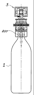
same objects on which the device according to the invention can be utilised.
The device for picking up, handling and moving objects which forms the subject
of
the present invention is designated, as a whole, by the reference number 1,
and is
suitable to fix an object 2 or, more particularly, a container 2, hereinafter
referred
s to also as "bottle 2" - see Figures 3a and 3b, to a conveyor 3 of the type
known as
"endless traction element" or an overhead chain conveyor. Without departing
from
the scope of the present invention, the conveyor to which one or more picking-
up
devices 1 are to be applied may be a rope-and-button conveyor, a belt
conveyor, a
carriage conveyor, a platform conveyor, a slat conveyor, or an apron conveyor,
~o and may also be a conveyor that stands on the floor or is located below
floor level,
or any other appropriate type of conveyor, to which the picking-up device 1,
instead of hanging, may be fixed underneath after being rotated through
180° with
respect to the position illustrated in Figure 1. In the following description
and in the
claims, the conveyor, designated by the reference number 3, is generically a
~s conveyor of any one of the aforementioned types.
The device for picking up, handling and moving objects illustrated in Figure 1
comprises a rail or supporting guide made of section bar 4 obtained in general
by
bending, and, only in certain portions of the conveyor, by extrusion in order
to
ensure a higher stiffness and precision of positioning, as will be explained
in
2o greater detail in what follows. The device of Figure 1 is used in a plant
(not shown)
for the moulding and treatment of plastic bottles in order to convey the
bottles from
the blow-moulding unit to the stations downstream thereof, for example the
coating
or spray-coating stations, and from here to a possible drying oven, heat-
treatment
station, and/or a station for stacking or unloading the finished products.
2s The device 1 for picking up, handling and moving objects shown in Figure 1
comprises a vertical shaft 5 inserted in a housing 6, on which there rotate,
coaxially to the shaft 5, two rolling wheels (or bearings) 7a, 7b with
vertical axis.
Integral with the housing 6 is a horizontal shaft 8 on which there rotate two
wheels
(or bearings) 9a, 9b with horizontal axis. The shaft 5 can be fixed to a
conveyor 3
3o in a wide range of ways; for example, it can be fixed in the middle of a
chain
element of a conveyor 3, at some distance from the wheels 7a, 7b, 9a, and 9b.
The conveyor 3 can be of the. type with just wheels with horizontal axis 9a,
9b or
CA 02439411 2003-08-26
WO 02/068300 PCT/EP02/01949
6
any other known conveyor of a suitable kind.
In the example of Figure 1, the vertical shaft 5, supported by anti-friction
bushings,
can turn about its own longitudinal axis with respect to the housing 6 and to
the
section bar 4, and can receive a rotational torque by means of the pinion gear
10
s that is coaxial to it - for example the pinion gear 10 can be fixed on the
shaft 5,
either with an interference fit, or else with a slot-and-dowel, with an
elastic pin 101
(see Figure 1 b) or a taper pin.
As is known from the prior art, the pinion gear can be set in rotation, for
example
by a second drive chain which slides in the opposite direction to that of
advance of
io the conveyor 3. Alternatively, once more according to the prior art, it is
possible to
replace the drive chain + pinion gear system 10 for example with a V-belt +
pulley
system, or else a plane belt + friction wheel system.
According to an aspect of the present invention, the device 1 for picking up,
handling and moving objects comprises picking-up means, usually called chuck,
~s 20 suitable to grip and withhold the container 2 from inside the open end
200 (in
the example shown, the picking-up means grip the bottle 2 from inside its neck
200 - Figure 3), and further comprises a protective sliding sleeve 7 suitable
to
cover and protect a predetermined portion of the object or container in the
proximity of the open end 200 of the container 2, and is characterised in that
the
2o actuation for picking up or releasing the object 2 by the picking-up and
withholding
means 20 is independent of the movements of sliding of the sleeve 7 with
respect
to the ensemble of the device 1 for picking up, handling and moving objects.
In
fact, in the example illustrated, on the vertical shaft 5 and coaxially to it
there is
fixed - for example with one of the aforementioned systems for fixing the
pinion
2s gear 10 to the shaft 5 - an intermediate element 11, on which the picking-
up
means 20 are fixed and blocked both axially and in such a way as to prevent
rotation by means of a ball-type press-block coupling (described in greater
detail in
what follows). Made of a single piece with the picking-up means 20 is also a
flange
11A having a slotted outer edge 11C which is complementary to the internal
3o slotted section 7A of the sliding sleeve 7, with which it engages in such a
way that
it can slide therein longitudinally, transmitting driving torque parallel to
the axis of
rotation of the shaft 5 - the slotted coupling can be replaced by other modes
of
CA 02439411 2003-08-26
WO 02/068300 PCT/EP02/01949
7
connection that enable vertical sliding with the transmission of a torque -.
That is,
the slotted external edge 11 C constitutes a slide guide, on which the sleeve
7
slides. The picking-up means 20 in the preferred embodiment of Figure 1
consists
of a radially expandable ring of elastic, or anyway deformable, fingers,
extensions
s or prolongation 11 B - made preferably of an injectable technopolymer with
sufficient wear resistance, and resistance to temperature and chemical agents -
,
which rest, in a position corresponding to an internal groove (Figure 1 a), on
an
annular spring 21 set inside the aforesaid ring and positioned roughly
perpendicular to .the longitudinal axis of the ring. The annular spring 21
enables
io the ring of elastic prolongations 11 B to expand or contract with an easily
controllable radial elasticity (chiefly dependent upon the elastic
characteristics of
the wire of the spring and of its positioning along the axis of the ring), and
enables
solution of the problems of fatigue failure which elastic elements made of
plastic
material presented in the past.
~s The thickness and shape of the elastic prolongations are adapted to the
container
that is to be conveyed, in order to support it more or less rigidly according
to the
process specifications (for example, speed, angular velocity, format of the
container or preform, weight of the container or preform, design of the
thread,
temperature, etc.).
2o Advantageously the injectable polymer, of which the ring of the elastic
prolongations 11 B is made of, is polyvinylidene fluoride (PVDF) or another
fluorine
polymer or copolymer; the use of PVDF in carrying out the chuck 20 provides
good
friction forces with the bottleneck to be grasped; as further advantages, in
this
applications PVDF provides a good resistance to relatively high temperatures,
2s around 100° to 120°C and wear, or erosion, resistance.
With this kind of picking-up means 20 it's possible to hold a bottle even with
relatively high spinning rates, e.g. of up to 1100 rpm, or more, as better
described
hereinafter.
As it will become apparent from the description of another embodiment -shown
in
3o Figure 6 and better described later- of a device according to the present
invention,
the chuck 20 can be used also in devices for picking up, handling and moving
containers without a protective sliding sleeve 7, for applications where no
CA 02439411 2003-08-26
WO 02/068300 PCT/EP02/01949
8
particular protection is needed.
Referring again to the embodiment shown in Figure 1 and 1 a, also made
integrally
with the picking-up means 20 is a first male element 22 of the ball-type press-
block
coupling mentioned above; the female element of the ball-type press-block
s coupling is made instead on the bottom part of the intermediate element 11.
The
ball-type press-block coupling is completed by a tubular element 12 (Figure 1
) the
bottom end of which has internally a re-entrant surface shaped like the
frustum of
a cone. Preferably - but not necessarily - three balls 23 are housed inside
the
through holes in the vertical wall of the intermediate element 11. The balls
jam in
~o an annular groove 24 (Figure 1a) or in a series of recesses suitable to
transfer the
moment generated by the rotation, made on the male part of the press-block
coupling. The balls 23 are pushed towards the inside by the re-entrant surface
shaped like a truncated cone (or by another system based on an inclined plane)
since the tubular element 12 is pushed upwards by a first spring 13. The
picking-
Is up means 20 can be rapidly slid out by pushing the tubular element 12
downwards.
The sequence of the fast-coupling operation of the picking-up means 20 on the
device 1 of Figure 1 is shown in Figures 2a-2e.
The chuck 20 in Figure 1 are made hollow with an internal through hole through
2o which an electrode 17 for electrostatic coating, the nozzle of a filler, or
other
elements which are to enter the bottle 2, can pass and come out.
The sliding sleeve is constantly pressed downwards by a second spring 14
compressed between a bottom internal projection of the sleeve and the sliding
flange 11A with slotted edge, and it is prevented from sliding out by an
annular
2s plug 15, which is snap-fitted into the top part of the sliding sleeve 7 and
which
bears upon the slotted flange when the device 1 for picking up, handling and
moving objects is not gripping any bottle 2 and is empty.
Raising of the sliding sleeve 7 can be controlled, for example, by a cam-type
actuator made by providing on the sleeve a flange 16, which, during horizontal
3o advance of the device 1, can be raised sliding on a pair of plane bars 24,
which
are also preferably made of technopolymers with an appropriate wear resistance
and a low coefficient of sliding friction, for example, polyimide or
polyphenyl resins,
CA 02439411 2003-08-26
WO 02/068300 PCT/EP02/01949
9
such as polyetherimide (PEI) or polyvinylidene fluoride (PVD), according to
systems in themselves already known (Figures 3a and 3b). The bar 24 is
inclined
with respect to the horizontal, the rail 3 is horizontal, and H1 is greater
than H2.
When the conveyor advances, the flange 16 rests on the strip 24 and is pushed
by
s the latter upwards (Figure 3b).
If necessary, the surface 18 of the ring of the elastic prolongations 11 B,
which is
the axial abutting end for the fitted bottle 2, is located lower down (Figure
1 a,
height H) than the grooved flange 11A, so that the sliding sleeve 7, when it
is
raised, can conveniently uncover the entire neck and threaded part of the
bottle.
~o Advantageously, both the sliding sleeve 7 and the bars 24 - which are on
the fixed
supporting frame of the conveyor - of the cam-type actuation are made of
appropriate technopolymers, which are sufficiently resistant to wear and which
have low coefficients of sliding friction.
A device 1 for picking up, handling and moving objects, provided with the
sliding
~s sleeve 7, the annular plug 15 and the chuck 20 made of plastic material,
can be
injection-moulded at a low cost, has a very small weight and inertia, and the
vibrations during a possible fast rotation of the bottle are such that the
entire
conveyor is subjected to less stress.
In addition, the above three plastic components, which in the device 1 are the
20 ones most subject to wear during operation, can be quickly replaced in a
single
operation, thanks to the ball-type press-block coupling, during extraordinary
maintenance. Since in a plant for the production of bottles by blow-moulding,
the
devices 1 for picking up, handling and moving objects frequently number some
hundreds, if not thousands, the overall saving is all the more evident.
2s If appropriate technopolymers are chosen, these three plastic components
will
only need to be replaced once a year for reasons of wear and they will be able
to
stand up to the aggressive environments of present-day industrial processes.
Instead, the intermediate element 11 and the tubular element 12 are preferably
made of metal.
3o There follows a description of the operation of the device of Figure 1.
A bottle 2, or a generic container 2 having an open end 5 is pushed upwards
against the ring of elastic extensions or prolongations 11 B into a loading
station, in
CA 02439411 2003-08-26
WO 02/068300 PCT/EP02/01949
a known way. The ring of prolongations is driven into the neck 200 of the
bottle 2
and, by friction, blocks the bottle 2 axially as well as preventing it from
rotating.
The second spring 14 keeps the sliding sleeve 7 pressed so that the latter
bears
upon one part of the bottle (for example, the collar or the tear-seal flange -
Figure
s 5), in such a way as to isolate the neck 200 and obtain, as far as possible,
a seal
with respect to the outside environment, also depending upon the presence of
other solution - if any - such as providing a seal on the annular ring of the
sleeve
which comes to bear upon the bottle 2. Clearly the shape, diameter, and travel
of
the sleeve 7 are designed according to the shape of the bottle or container
and of
to the part of the bottle or container which the sleeve, when lowered, must
isolate
and protect from the outside environment.
In this way, the sliding sleeve 7 also constitutes an additional protection
and
isolation - in combination with the picking-up means 20, which might
occasionally
be faulty - of the internal cavity of the bottle 2 not only against paint and
solvent,
is but also against other external contaminants, such as lubricants.
The bottle 2, produced, for instance, by blow-moulding, or by any other
suitable
technique, can thus be transported on an automatic conveyor 3 through the
various processing stations downstream of the moulding station. In the case of
a
bottle made of PET, for example, the moulded bottle may pass through an HVLP
2o spray-coating or electrostatic-coating station, for example for a colouring
treatment
or a treatment of impermeakiilization to C02 or to molecular oxygen, as in the
case
of bottles for effervescent beverages, fruit juice or beer, or in any case
beverages
that are sensitive to attack by oxygen and to loss of C02, without the region
covered by the sliding sleeve for instance, the region of the neck and of the
thread
2s of the bottle, getting coated.
During the spray-coating operation, frequently the bottle must undergo
spinning, at
a speed of some 300 to 1100 rpm., and this is done, for instance, as was
mentioned previously, by causing the pinion gear 10 to engage with a second
drive chain which slides in a direction opposite to the direction of advance
of the
3o chain conveyor 3.
Advantageously, along the zones of the conveyor 3 in a position corresponding
to
the second driving chains, the wheels 7A, 7B, 9A, 9B of the devices 1 are
caused
CA 02439411 2003-08-26
WO 02/068300 PCT/EP02/01949
to slide within a precision-manufactured section bar 4, leaving an amount of
play,
between the wheels and the sectional strips 4, smaller than in the remaining
stretches of the conveyor. This reduces the horizontal deflection of the
device 1
under the thrust that the second drive chain exerts on the pinion gear 10.
s Downstream of the coating station (or whenever it is necessary), as the
conveyor
3 continues on its way, the sliding sleeve 7 is raised, for instance by means
of a
cam-type system (Figures 3a and 3b); thus uncovering the neck 200 and the
threaded region of the bottle, which, since they have not been coated, can be
gripped, for example with mechanical grippers or other devices, even when the
~o coating has not yet dried, in order to unload the bottle from the chain
conveyor.
Figures 4 and 5 are schematic illustrations of a second preferred embodiment
of a
device for picking up, handling and moving objects according to the present
invention, in which the sliding sleeve 70, the springs 140 and 130, the
tubular
element 120, the intermediate element 110, the picking-up means 60, and the
is annular plug 150 correspond to, and have similar modes of operation as,
respectively, the items designated by 7, 14, 13, 12, 11, 6 and 15 of Figure 1,
previously described, whilst the shaft 50 for fixing to the conveying chain
cannot
rotate about its own axis, and the sleeve 70 + picking-up means 60 system can
rotate on a vertical axis thanks to the bushings 180 and 190 set between the
2o intermediate element 110 and the two elements 185 and 195, which are fixed
with
respect to the shaft 50.
The sliding sleeve 70 can be set in rotation by a pulley, belt or cable which
slides
in a direction opposite to that of advance of the device 1 along the conveyor
3 and
which grips inside the seat 170 made on the double flange similar to the
flange 16
2s of Figures 3a and 3b. Also the double flange has the function of raising
the sleeve
70 by means of an external-cam system 24, as illustrated in Figures 3a and 3b.
Figure 6 shows another embodiment of a device for picking-up, handling and
moving object according to the present invention:
the device in Figure 6 differs from the device in Figure 1 in that the sliding
sleeve 7
3o is not present, and chucks 20 are used, comprising the radially expandable
ring of
elastic or resilient extensions 11 B, made preferably of an injectable
technopolymer. Like in the embodiment of Figure 1 a, the ring of extensions 11
B
CA 02439411 2003-08-26
WO 02/068300 PCT/EP02/01949
12
rests, in a position corresponding to an internal groove (Figure 1 a), on an
annular
spring 21 set inside the aforesaid ring and positioned roughly on a plane
perpendicular to the longitudinal axis of the ring.
The thickness and shape of the elastic extensions are adapted to the container
s that has to be conveyed, in order to support it more or less rigidly
according to the
process ,specifications, for example, conveying speed, angular velocity,
format of
the container or preform, weight of the container or preform, design of the
thread,
temperature, etc. Some advantages of using this kind of picking-up means have
already described previously; moreover, the ring of resilient prolongations is
to suitable to be easily produced by injection moulding of polymer materials
with a
relevant reduction of the cost of each device; the whole conception of the
picking-
up means with a ring of resilient prolongations resting on an elastic element
is
cheap and simple to be made.
The devices described above merely by way of example can clearly undergo
Is numerous other variations without thereby departing from the scope of the
present
invention. For instance, it is possible to vary the type of fixing of the
picking-up
device 1 to the chain conveyor: the vertical shaft 5 may be either rotating or
fixed,
and may be positioned either in the vicinity of or at a distance from the
wheels of
the chain of the conveyor. Likewise, the device 1 for picking up, handling and
2o moving objects can be used for handling an extremely wide range of objects,
including semi-finished products, such as preforms or parisons for blow-
moulding;
the flange 16 can be modified and replaced by one or more segments of flange
or
by an appropriate radial projection of the sliding sleeve 7, designed to raise
the
latter, sliding on an external cam; the annular spring 21 can be replaced
generally
2s with other radially resilient elements; the first male element 22 (Figure
1a) integral
with the picking-up means 20 can also be a metal insert around which the
plastic
body of the picking-up means 20 are co-moulded; further modifications are
anyway possible.