Note: Descriptions are shown in the official language in which they were submitted.
CA 02439445 2003-08-29
WO 01/39569 PCT/CHO1/00156
- 1
Method for establishing a detachable mechanical and/or
electrical connection
The present invention is generically directed to mechanical
links between modules of a hearing aid apparatus, so as to
construe the hearing aid apparatus or between a hearing aid
apparatus and an additional appliance.
It is further directed to a technique for establishing an
electrical connection, again either between modules
concomitantly defining the hearing aid apparatus or between
a hearing aid apparatus and an additional appliance.
It is known from the US-A-6 157 728 to transmit electrical
signals to a therapeutical outside-the-ear hearing aid
apparatus via an inductive link. In the transmission cable
as an additional appliance to the hearing aid apparatus
there is provided an induction coil wound around a
cylindrical magnet. The axis of the cylindrical magnet is
perpendicular to a surface along which the cable's plug is
applied to the hearing aid apparatus. Within the hearing
aid apparatus there is provided a disk-shaped ferromagnetic
plate adjacent to the respective surface of the hearing aid
apparatus, to which the plug is to be joined. The
cylindrical magnet, on the one hand, and the disk-shaped
ferromagnetic plate, on the other hand, simultaneously form
the mechanical link between the appliance and the hearing
aid apparatus and the electrical inductive connection
between the appliance and electronic cor.ponents within the
hearing aid apparatus.
Thereby, analogue signals as audio signals are transmitted
between the inductive link of induction coil with
BESTATIGUNGSKOPIE
CA 02439445 2003-08-29
WO 01/39569 PCT/CHO1/00156
- 2
cylindrical magnet core on the side of the appliance and
ferromagnetic plate as receiver part on the side of the
hearing aid apparatus.
Although being advantageous with respect to easy mechanical
linking of the appliance to the hearing aid apparatus by
the user carrying the hearing aid apparatus at his ear,
this technique suffers different drawbacks:
~ Due to the arrangement of the ferromagnetic plate
perpendicularly to the axis of the cylindrical magnet,
once the appliance is mounted to the hearing aid
apparatus, this ferromagnetic plate considerably shunts
and thus dampens in particular high frequency signals to
be transmitted.
~ Due to the fact that the ferromagnetic plate has two
objects, namely contributing to the mechanical link as
well as contributing to the electric signal
transmission, a compromise solution as with respect to
the material of the ferromagnetic plate on the one hand
for signal transmission, on the other hand for
mechanical linkage purposes must be made, which may not
be optimum for both objects.
~ Due to the inductive link, whereat parts, namely the
ferromagnetic plates, are used for both objects, namely
mechanical and electrical link, there is an
interdependency between mechanical and electrical link
quality, which, as was said, may not be construed
optimally for both purposes.
CA 02439445 2003-08-29
WO 01/39569 PCT/CHO1/00156
- 3 -
It is an object of the present invention to remedy for the
above mentioned drawbacks of the prior art technique as
mentioned as concerns mechanical links and as concerns
electrical links, and further as concerns combined
electrical and mechanical links. Thereby, the principal
advantage of easily handable as realized by the prior art
teaching shall be maintained.
With respect to mechanical linking, this target is reached
according to the present invention by the method for
establishing a detachable mechanical link at a hearing aid
apparatus by establishing an exclusively mechanical link
magnetically.
Thereby, the high advantage of easily establishing such a
link by the user is maintained, but functionally the
magnetical link per se does not contribute or affect any
electrical link.
In a preferred embodiment of the invention the magnetical
link is established between at least two modules of the
hearing aid apparatus, which concomitantly define the
hearing aid apparatus or to a hearing aid apparatus and an
additional appliance.
Although inventively, the mechanical link which is
established magnetically does not form part of an
electrical link in the sense of not affecting the quality
of the electrical link, in a preferred embodiment of the
present inventive method by establishing the mechanical
link there is established an electrical connection, but
separate from the mechanical link.
CA 02439445 2003-08-29
WO 01/39569 PCT/CHO1/00156
- 4 -
In a further preferred embodiment the attracting force of
the magnetical link is exploited to establish a
predetermined relative positioning of the parts by
establishing the mechanical link.
In a further preferred embodiment and again exploiting
polarity of a magnetic linkage, the mechanical link is
enabled or disabled by appropriately selecting polarity
direction of at least two magnets for the mechanical
linking. If the inventive mechanical link is to be realized
by two magnets, one magnet on each part to be linked, then
mutual polarity directions of these magnets will
automatically control, whether the two parts may be
mechanically linked or not. In one mutual polarity
distribution the magnets will be mutually attracted,
thereby enabling the mechanical link, in the other they
will be magnetically separated, thereby disabling such
mechanical link.
In a further preferred embodiment the mechanical link is
established on the one hand to a part of the hearing aid
apparatus, which comprises the signal processing modules
and on the other hand at least one of the following parts:
- a battery or accumulator module
- an emitter and/or receiver module
- a filter module
- a microphone module
- an optical or an electrical cable.
In a first preferred mode of the inventive method, whereat,
as was mentioned above, by means of establishing the
CA 02439445 2003-08-29
WO 01/39569 PCT/CHO1/00156
- 5 -
mechanical link there is established separate therefrom an
electrical connection, it is proposed to establish as an
electrical link a galvanic electrical connection. This may
e.g. be realized in that by establishing the mechanical
link magnetically a pair or more than one pair of
electrical contacts are established.
As was mentioned above, the mere fact that an inductive
link between two parts to be electrically connected from or
at a hearing aid apparatus prevents optimum exploitation of
establishing the mechanical link magnetically, which on the
other hand has high advantages with respect to easy
establishment by the user. Additionally, and as may be seen
e.g. from the above mentioned US 6 157 728, an inductive
link necessitates at least on one of the two parts a
coil/magnet arrangement, which obstructs quite a part of
volume, which is for any hearing aid appliance always of
high disadvantage. Also in view of this additional
disadvantage it is inventively proposed a method for
establishing an electrical connection to or in a hearing
aid apparatus by establishing the electrical connection via
a series capacitor, thereby exploiting a part of the
hearing apparatus' casing as the dielectricum of the
capacitor.
This approach to electrical connection enables realization
of an additional mechanical link magnetically, as was
discussed above a:~d without that requirement =or the
mechanical link would interfere with the reauirements for
the electrical connection. Therefore, in a preferred
realization form, the capacitive electric link technique is
CA 02439445 2003-08-29
WO 01/39569 PCT/CHO1/00156
- 6 -
combined with the inventive magnetic/mechanical link
technique as was explained above.
In a preferred form of the latter technique, there is
established the electrical connection between an electrical
cable and an electric tab at the casing of the hearing aid
apparatus, thereby exploiting a part of the casing as the
dielectricum of the series capacitor.
In a further preferred mode of realization the connection
is established to a one-lead electric cable and the
electronic circuitry within the hearing aid is
operationally connected on the one hand capacitively to
said one-lead electric cable, and on the other hand to a
body contact electrode, the electric potential of this body
contact electrode being exploited as said electronic
circuitry as a reference potential. In other words, the
electronic circuitry of the hearing aid apparatus is driven
on the potential of the user's body, which body performs
closure of an electrical current loop from said one-lead
electric cable to the electronic circuitry back to the
source of signals transmitted to the electronic circuitry.
In a further preferred embodiment the hearing aid apparatus
is an in-the-ear hearing aid apparatus or an outside-the-
ear hearing aid apparatus, both for impaired hearing
individuals or for not hearing impaired individuals just as
a hearing aid, or is an earphone apparatus.
The cable, especially the one-lead electric cable, is in a
preferred further embodiment a connecting cable to a
transmitter module remote from the hearing aid apparatus or
a linking cable to a programming unit for programming the
CA 02439445 2003-08-29
WO 01/39569 PCT/CHO1/00156
hearing aid apparatus. Such a transmitter module may be
realized by a Bluetooth converter or by an external player
as a minidisk player, and MP3 player, a CD player etc.
In a further preferred embodiment the said cable forms at
least a part of a binaural link from one hearing aid
apparatus to a second one.
In a highly preferred mode of operation digital signals are
led through said series capacitor as especially digitally
controlled signal traits.
To fulfill the above mentioned object there is further
proposed a hearing aid apparatus comprising at least two
releasable modules as the at least two linkable parts with
mechanical linking members or with an additional appliance
as one linking part removably linkable to the hearing aid
apparatus as a second linking part by mechanical linking
members, wherein the mechanical linking members comprise at
least one magnet.
In a preferred embodiment there is provided, in the area of
the mechanical link to be established at at least one of
the linking parts, a magnet arrangement, preferably a
permanent magnet arrangement, and there is further
provided, at the other of said linking parts, as was
mentioned, a magnet arrangement as well or a counterpart of
ferromagnetic material. In a further preferred embodiment
of the inventive hearing aid apparatus the mechanical
linking members are the mechanical linking members for an
electrical connection.
In a further preferred mode of realization the mechanical
linking members comprise guiding members, which ensure
CA 02439445 2003-08-29
WO 01/39569 PCT/CHO1/00156
_ g _
establishment of the mechanical link in a predetermined
mutual position of the linkable parts.
In a further preferred embodiment one part to be linked
comprises a signal processing module, and the other part is
one of the following parts:
- a battery or accumulator module
- a transmitter and/or receiver module
- a filter module
- a microphone module
- an optical or an electrical cable.
In a further preferred embodiment the mechanical linking
members are the mechanical linking members of an electrical
galvanic connection between the parts.
There is further proposed an inventive hearing aid
apparatus, still to resolve the problems discussed in
connection with the inventive method, with a detachable
electric connection, wherein the electrical connection
comprises a series capacitance, a part of a casing of the
hearing aid apparatus forming the dielectricum of the
capacitance.
Thereby, again preferred, the mechanical link for such
electrical connection is construed magnetically, as was
discussed above.
In a further preferred embodiment of the inventive hearing
aid apparatus the one part to be electrically connected is
the hearing aid apparatus, another part is a preferably
one-lead connecting cable.
CA 02439445 2003-08-29
WO 01/39569 PCT/CHO1/00156
- 9 -
Further preferably, the hearing aid apparatus comprises a
body-contacting electrode which is exposed to ambient. This
electrode, in use of the hearing aid apparatus, contacts
the human body, and electrical potential of this electrode
is exploited as the reference potential for the electronics
of the hearing aid apparatus, i.e. as ground potential.
The present invention shall now be described by way of
examples as shown in the following figures. These figures
show:
Fig. 1 schematically, the principal of the inventive
mechanical linking method as is provided at a
hearing aid apparatus according to the present
invention;
Fig. 2 in a representation form in analogy to that of
fig. 1, a further embodiment of the inventive
magneto/mechanical linking technique at a further
embodiment of a hearing aid according to the
present invention;
Fig. 3 still in a schematic representation according to
the figs. 1 and 2, a further improvement of the
inventive mechanical linking technique for
accurately positioning the parts to be linked as
realized at one embodiment of a hearing aid
apparatus according to the present invention;
Fig. 4 still in a representation in the schematic form
according to the figs. 1 to 3, realization of the
inventive mechanical linking method together with
galvanic electrical linking as realized in a
hearing aid apparatus according to the invention;
CA 02439445 2003-08-29
WO 01/39569 PCT/CHO1/00156
- 10 -
Figs. 5A and SB
schematically the principal of the method of
capacitively electrically linking as realized at a
further embodiment of a hearing aid apparatus
according to the present invention;
Fig. 6 still schematically the combination of series
capacitance electrical linking and of
magneto/mechanical linking as realized in a
hearing aid apparatus according to the present
invention;
Fig. 7 a further embodiment of combined
magneto/mechanical and series capacitance linking
according to the method and hearing aid apparatus
of the present invention;
Fig. 8 schematically an inventive hearing aid apparatus,
whereat two modules are linked
magneto/mechanically and/or by series capacitance
electric linking according to the present
invention, and
Fig. 9 a preferred embodiment of the present invention
according to which an external appliance as of a
preferably one-lead cable is temporarily applied
to a hearing aid apparatus to connect latter to a
Bluetooth device and/or a player device and/or a
control device and/or a hearing aid DSP
programming unit .
In fig. 1 there is schematically shown the principle of the
inventive mechanical linking. On a first part 1 to be
CA 02439445 2003-08-29
WO 01/39569 PCT/CHO1/00156
- 11 -
mechanically linked, be it a hearing aid apparatus or one
module of a hearing aid apparatus, there is provided a pole
piece 3 of ferromagnetic material. At the second part 5 to
be mechanically linked to the part 1, be it an appliance to
be removably linked to the hearing aid apparatus or be it a
module to concomitantly form a hearing aid apparatus
together with part 1, a magnet arrangement 7, preferably a
permanent magnet arrangement, is provided.
Obviously, instead of providing a pole piece 3 in fact
magnetically passive at one of the two parts, it is
absolutely possible to provide at both parts 1 and 5 an
active magnet arrangement, again preferably of permanent
magnets.
According to fig. 2, this embodiment is shown in that both
parts to be mechanically linked 1 and 5 comprise both
magnet arrangements 75 and 71 respectively. This technique
allows to prevent establishment of mechanical links between
parts or in positions of parts which shall not be
mechanically linked. As may be seen in fig. 2, if the
polarities P of the magnet arrangement, again preferably of
permanent magnets, are the same, then the two parts 1 and 5
will be attracted by the mutual magnetic force F, thereby
leading to the magnetical link as desired. Whenever the
polarities of the two magnet arrangements are inversed as
shown in dashed lines, then approaching the two parts 1 and
5 to be mechanically linked will be prevented by the
repelling force of the magnets.
Whenever a magneto-mechanical link is established between
the parts to be linked as was shown in figures 1 and 2,
CA 02439445 2003-08-29
WO 01/39569 PCT/CHO1/00156
- 12 -
such a mechanical link may be established, even if the two
parts are laterally and mutually slightly shifted, so that
an exact positioning of the two parts at the desired mutual
position may be not accurate and not accurately
reproducible.
Therefore, and as schematically shown in fig. 3, the
attracting magnetic force is generically exploited to draw
the two parts to be linked in an exact mutual position.
Therefore, and as schematically shown in fig. 3, there are
provided at one or at both of the parts 1 and 5 to be
linked mutually co-operating guiding members 9, which
automatically lead the two parts 1 and 5 to be mechanically
linked in an accurately defined mutual position by
exploiting the attracting force of the magnet arrangement
7.
As was mentioned above the inventively provided
magneto/mechanical link shall not interfere especially as
concerns selection of the material used for establishing
the magnetic link on the one hand and the electric link on
the other, but as again schematically shcwn in fig. 4, the
magneto/electrical link according to the present invention
may clearly be used for mechanically holding parts together
which are electrically linked.
According to fig. 4, e.g. at part 5 with the magnet
arrangement 75 one or more than one electric connection pin
11 may be provided as electric contact connected within
part 5 to respective electric leads 13. At part 1 there is
provided the magnet arrangement 71, again preferably of
permanent magnets, and the female counterparts 15 for the
CA 02439445 2003-08-29
WO 01/39569 PCT/CHO1/00156
- 13 -
pins 11 to establish respective electrical galvanic
connections. The female plugs 15 are connected to
electrical leads 17. By mechanically linking the two parts
1 and 5 there is established a galvanic electrical
connection of the contacting parts 11 and 15 without the
magnet arrangements at the respective part interfering or
affecting such electrical connection.
It has to be noted that by appropriately selecting the
polarities P of the magnet arrangement at the two parts 1
and 5, one can control in which position the two parts have
to be linked. If the magnet arrangements are e.g. formed by
respective permanent magnets distributed in an annular
pattern around a central axis A by appropriately selecting
the polarities of the magnets, it may be predetermined at
which mutual angle position cp the two parts 1 and 5 may be
magneto/mechanically linked, thereby defining for the
proper positioning of the electric contact parts 11 and 15
to be connected as desired.
Further, the technique of additionally establishing an
electric connection as of fig. 4 may be clearly be combined
with the positioning technique as schematically shown in
fig. 3 so as to establish proper mutual positioning for
installing proper and correct electrical connections.
In fig. 5A there is again schematically shown the principle
of establishing an electric connection according to the
present invention. A hearing aid apparatus or a module
thereof 21 comprises a shell or casing 23, wherein
electronic units, as e.g. a digital signal processing unit
27 is mounted.
CA 02439445 2003-08-29
WO 01/39569 PCT/CHO1/00156
- 14 -
A second part 25, as e.g. a second module forming together
with module according to part 21 the hearing aid apparatus
or being an appliance to be applied to the hearing aid
apparatus part 21 comprises a first capacitance electrode
30a, which is metallic and which, not necessarily but
preferably, has a metallic surface 32 exposed to ambient.
In the casing 23 of the second part 21 to be electrically
linked to part 25, there is provided a metallic electrode
30b being separate from the ambient U by a part 23d of
casing 23 being of a dielectric material, as of plastic
material of the casing 23. The electrode 30b is
electrically connected to the unit 27. When the two parts
25 and 21 are brought together there results a series
capacitance formed by electrode 30a, dielectricum 23d and
second electrode 30b. This capacitance C acts as series
signal-transmitting element between the two parts 25 and
21. It goes without saying that the dielectric covering may
also be applied to the surface 32 of electrode 30a or
exclusively to that surface.
The electronic unit 27 within the hearing aid module 21
gets its reference potential from a body-contacting
electrode 35. When applied to the human body, the electrode
35 assumes the local electric potential ~B of the body via
electrolytic contact, which may be improved by electrolytic
paste as known in medical electrode appliance art.
The capacitive link is most preferably exploited for
transmitting digital signals S#. Without having to recur to
relatively complicated chart amplifier circuitry and
dependent on the input impedance Z: of the unit 27 the
CA 02439445 2003-08-29
WO 01/39569 PCT/CHO1/00156
- 15 -
capacitance C acts as a voltage-differentiating element, so
that digital signals S# will be differentiated to impulses
I which may easily be detected at the unit 27. In a
preferred mode this capacitive connection is used to
transmit controlled signals and especially digitally
controlled signal traits.
In fig. 5B there is again schematically shown the principle
of establishing an electric connection according to the
present invention. In contrast to the embodiment shown in
fig. 5A the electrode 35, being the body-contacting
electrode according to fig. 5A, is embedded into the casing
23 which means that the body is also contacted by a
capacitive electric coupling as it is the case between the
first electrode 30a of the part 25 and the second electrode
30b of the casing 23. Furthermore, fig. 5B shows an
interface module IF in which desired signals can be
generated by a signal generator SG. The signal generator SG
is connected, on the one hand, to the first electrode 30a
of the part 25 and, on the other hand, to a ground
electrode IF GND which is preferably incorporated into the
interface module IF. In other words, there is provided a
further capacitive electric coupling to the body to close
the electric circuit.
Instead of completely incorporating the ground electrode
IF GND into the casing of the interface module IF resulting
in said further capacitive electric coupling one might also
provide a ground electrode which is in direct contact with
the body similiarly to the arrangement of fig. 5A where the
electrode 35 is directly contacting the body.
CA 02439445 2003-08-29
WO 01/39569 PCT/CHO1/00156
- 16 -
As shown in fig. 6 such series capacitance coupling by
means of series capacitance element C may easily and most
advantageously be combined with the magneto/mechanical
linking technique as was described with the help of figures
of 1 to 4.
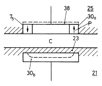
It is even possible, as shown in fig. 7, to use one of the
two electrodes 30a or 30b or even both these electrodes as
magnet arrangement, because the magnetic field generated by
the magnet arrangements will not interfere with the
capacitive electric coupling. As shown in fig. 7, the
electrode arrangement 30a at part 25 comprises the magnets
of the magnet arrangement 75. At part 21 the counter
electrode 30b is formed of ferromagnetic material. Thus,
when approaching the two parts 25 and 21, the two
electrodes 30a and 30b will be attracted snugly towards
each other with dielectricum layer 23 embedded
therebetween, and the magnet arrangement 75 with the
polarities P as shown in fig. 7 will generate the magnetic
field through electrode 30b acting as a pole piece.
An additional pole piece 38 may be applied at part 25 to
complete the magnetic circuit. Nevertheless, the magnetic
field and the ferromagnetic material of the electrode 30b
will by no means interfere with the capacitive coupling,
because with respect to the material of the electrode 30b
there is not requested a high electro conductivity. Thus,
the principle of series capacitance signal transmission and
of magneto/mechanical linking may be ideally combined,
thereby exploiting the electrode for the capacitance
coupling simultaneously as part of the magnetic link
CA 02439445 2003-08-29
WO 01/39569 PCT/CHO1/00156
- 17 -
arrangement. This is much more critical with an inductive
coupling, as its magnetic field may clearly interfere with
inductive transmission.
As schematically shown in fig. 8, the magneto/mechanical
link and/or the series capacitance electric link may be
applied between modules 40 and 42 concomitantly forming a
hearing aid apparatus 50, one module, e.g. module 40,
comprising electronic circuitry 44 to be e.g. electrically
supplied by means of a battery or accumulator 46 within
module 42.
Module 42 may thereby be a battery or accumulator module,
an emitter and/or receiver module, a filter module, a
microphone module. The electric and/or mechanical link as
is applied between the two modules 40 and 42 and as was
explained by figs. 1 to 7 is denoted in fig. 8
schematically at 46.
In an especially preferred mode of realization and
according to fig. 9 the magneto/mechanical link and thereby
preferably combined with the series capacitance electrical
link is applied between a hearing aid apparatus 52 and an
external appliance, especially a cable connector 54,
thereby especially preferred with a one-lead 56 cable.
Looking back on fig. 5A it is only then when part 25 does
not provide for a second lead with reference potential that
the body contact electrode 35 is to be provided. It is
clear that reference potential may also be provided to unit
27 by galvanic contact to a reference potential lead, as
shown in fic. 5A in dashed lines and at reference number
31.
CA 02439445 2003-08-29
WO 01/39569 PCT/CHO1/00156
- 18 -
Back to fig. 9 the preferably one-lead connection 56 may
establish connection of the hearing apparatus 52 to a
Bluetooth device 58 and/or to a player unit 60, e.g. a
minidisk, CD or MP3 player; or to a remote control unit 62
or, and especially, to a programming unit 64 for
programming the digital signal processing in the hearing
aid, e.g. at the audiologist.
It is pointed out that the battery or accumulator module
incorporated into the hearing aid apparatus can be used as
electrode, be it the second electrode, be it the body-
contacting electrode, to perform capacitive electric
coupling. Furthermore, provided that the casing of the
battery or accumulator module is made of a ferromagnetic
material, this module may also be used to establish the
mechanical link.