Note: Descriptions are shown in the official language in which they were submitted.
CA 02439627 2003-08-28
WO 02/074438 PCT/SE02/00531
STRUCTURAL UNITS THAT DEFINE FLUIDIC FUNCTIONS
TECHNICAL FIELD
The present invention concerns a microfluidic device in which there is a
microchannel
structure which comprises (a) one or more inlet ports, (b) one or more outlet
ports, and (c)
a structural unit which comprises a fluidic function and is located between
one of the inlet
ports and one of the outlet ports. The term "outlet port" includes~that the
port is an outlet
for liquid and/or an inlet and/or an outlet vent to ambient atmosphere. The
structural unit
(c) may include an inlet or an outlet port. There may be two or more
structural units
having the same or different fluidic function between an inlet port and an
outlet port.
The microchannel structure of the present invention is intended for transport
and
processing of one or more liquid aliquots. The aliquots may have the same or
different
compositions.
The invention also concerns various methods in which the microfluidic device
is used.
DRAWINGS
The structural units (functional units) are illustrated in figures 2-13. The
view is from
above. The cross-sectional areas are typical rectangular.
Figure 1 illustrates the definitions of "edge" and "circumferential zone".
Figure 2 illustrates a functional unit that enables split flow (unit 1).
Figures 3a-c illustrate a functional unit that enables mixing (unit 2).
Figures 4a-c illustrate a functional unit that enables partition of a larger
liquid aliquot to
smaller aliquots and distribution of these into different microchannel
structures (unit 3).
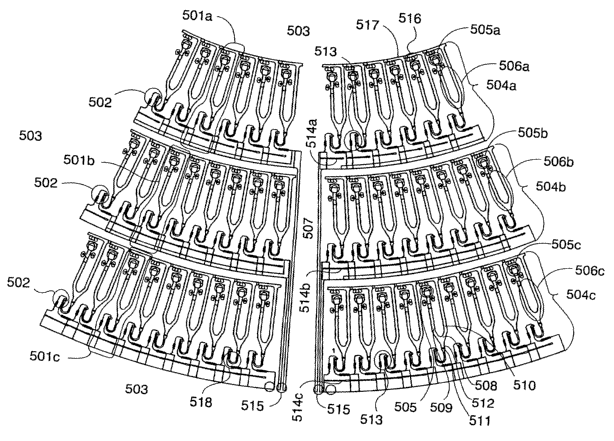
Figure 5 illustrates a plurality of microchannel structures that has been
arranged in
subgroups in the form of three annular rings/zones on a planar substrate and
functional
units that are preferred for this kind of arrangement (unit 4).
Figures 6a-c illustrate a functional unit that enables transport.back and
forth of a liquid
aliquot within a microchannel structure (unit 5).
Figures 7a-b illustrate a functional unit that enables controlled evaporation
(unit 6).
Figure 8 illustrates a functional unit that comprises anti-wicking means (unit
7).
CA 02439627 2003-08-28
WO 02/074438 PCT/SE02/00531
Figure 9 illustrates a functional unit in which it is possible to create a
liquid flow that has
front zone with a different composition compared to the bulk flow (unit ~).
Figure 10 illustrates a functional unit that comprises a non-closing inner
valve (unit 9).
Figure 11 illustrates a functional unit that facilitates liquid penetration
from an inlet port
(unit 10).
Figure 12 illustrates a functional unit that comprises a volume-defining
structure that can
be integrated in a microchannel structure (unit 11).
Figure 13 illustrates a functional unit that enables physical separation of
particulate
material from a liquid (unit 12).
GENERAL DEFINITIONS
The terms "microformat", "microchannel" etc contemplate that a microchannel
structure
comprises one or more cavities and/or channels that have a depth and/or a
width that is <_
103 Vim, preferably <_ 102 Vim. The lower limit for the width/breadth is
typically
significantly larger than the size of the largest reagents and constituents of
aliquots that
are to pass through a microchannel. The volumes of microcavities/microchambers
are
typically <_ 1000 n1, such as _< 500 n1 or <_ 100 n1 or <_ 50 n1 (nano-litre
range).
Chamberslcavities directly connected to inlet ports may be considerably
larger, e.g.
microchambers/ microcavities intended for application of sample and/or washing
liquids.
Typical volumes in these latter cases are within intervals such as I-10 ~.1, I-
100 ~,1, 1-
1000 ~.1 (mikro-litre range) or even broader intervals.
The present invention is primarily intended for geometric arrangements in
which the
microchannel structure is present in a substrate having an axis of symmetry
(spinning
axis). The term "radial distance" means the shortest distance between an
object and the
axis of symmetry. A microcha.nnel structure has an inlet port which is
upstream a
structural unit. The radial distance for an inlet port and a structural unit
may be the same,
or the inlet port may be at a shorter or longer radial distance compared to
the structural
unit. In a typical case there is also an outlet port for liquid downstream the
structural unit,
which in most cases is at a larger radial distance than the inlet port. The
microchannel
structure may or may not be oriented in a plane perpendicular to the axis of
symmetry. By
spinning the substrate around its axis of symmetry (spinning axis), a liquid
aliquot
positioned at a particular radial position, for instance in a particular
structural unit, will be
CA 02439627 2003-08-28
WO 02/074438 PCT/SE02/00531
subjected to a centrifugal force tending to drive the liquid outwards towards
the periphery
of the disc. In this way a liquid aliquot may be transported from an inlet
port to an outlet
port via a functional unit if the microchannel structure is designed to permit
this. In this
kind of systems a "higher" or an "upper" level/position will be at a shorter
radial distance
(inner position) compared to a "lower" level/position (outer position).
Similarly, the terms
"up", "upward", "inwards", and "down", "downwards", "outwards" etc will mean
towards and from, respectively, the spinning axis. This terminology applies if
not
otherwise is specified.
With respect to other arrangement/substrates and conventional driving forces,
i.e. gravity
force, externally applied pressure, electro-osmotically (electrokinetically.
electroendoosmosis etc) driven flows etc, these terms have their conventional
meaning.
The terms "downstream" and "upstream" are related to the process protocols and
liquid
flow as such. The terms thus refer to the order in which a unit, a part, a
process step, etc is
utilized. A downstream position is coming after an upstream position.
Axes of symmetry are n-numbered (Cn) where n is an integer between 2 and oo,
preferably
6, 7, 8 and larger, for instance oo. In preferred cases the substrate as such
has a cylindrical,
spherical or conical symmetry (C~).
A preferred substrate is in the form of a disk.
Each microchannel structure of the invention contains the functional units
necessary to
carry out a predetermined protocol within the structure. Parts that are common
for several
microchannel structures, such as common distribution channels, common waste
channels,
common inlet ports, common outlet ports etc, are considered to be part of each
microchannel structure to which they are connected.
The term microconduit means a part of a microchannel structure.
If not otherwise indicated the term "edge" of a microchannel/microconduit will
refer to
the intersection of two inner walls of a microchannel. This kind of edges is
typically more
CA 02439627 2003-08-28
WO 02/074438 PCT/SE02/00531
or less length-going in the flow-direction. See figure 1 which shows a
microchannel
having a rectangular cross-section (101), four inner walls (102) with four
wall
intersections or edges (103). The arrow (105) gives the flow direction.
A circumferential zone of a microchannel is also illustrated in figure 1. It
is a surface zone
(104) in the inner wall of a microchannel and extends in a sleeve-like manner
fully around
the flow direction (105). The length of this kind of zone is at least from 0.1
to 10, 100,
1000 or more times the breadth or depth of the microchannel/microconduit at
the
upstream end of the zone. A "segment" (106) of a circumferential zone is a
part that
stretches across the zone in the flow direction (flow-directed segment). A
segment may
extend into one, two, three or four of the inner walls of the microchannel.
The term "surface characteristics" refers to the surface of an inner wall of a
microchannel.
In the context of the invention the term contemplates mainly two subgroups:
(i) geometric surface characteristics, for instance presence of
projections/protrusions
from and depressions in the inner wall, and
(ii) chemical surface characteristics.
Wettability of a surface depends on surface characteristics and on properties
of the liquid
aliquot in contact with the surface. Wettability is often measured as the
liquid contact
angle: By the term "wettable" is mostly contemplated that the liquid contact
angle is _<
90°, such as <_ 70° or <_ 40°. By the term "non-wettable"
is mostly contemplated that the
liquid contact angle is >_ 90°. The term non-wettable may sometimes
refer to liquid
contact angles that are less than 90°, e.g. >_ 40° such as >_
70°, however, it then mostly
refer to a bordering area that has a lower liquid contact angle. The liquid
contact angle in
the normal case refers to equilibrium contact angles although it sometimes may
refer to
receding and/or advancing contact angles depending on the purpose of a
measurement. In
the context of the invention equilibrium contact angles are primarily
contemplated. The
figures given refer to values at the temperature of use. Non-wettable surfaces
are often
called hydrophobic, in particular in relation to aqueous media.
CA 02439627 2003-08-28
WO 02/074438 PCT/SE02/00531
The term "inner valves" refers to valves in which the passage or non-passage
depends on
physico-chemical properties of the liquid and the material in the inner wall
surface of a
microconduit and/or the curvature of the microconduit in the valve.
The term "non-closing valves" refers to valves in which a liquid is stopped at
the valve
even if the microconduit at the valve position is opened. This kind of valves
may also be
called passive valves.
The term "closing valves" refers to valves in which a valve part is used to
physically close
a microconduit.
The term "geometric valves" means that the valuing function is obtained by a
specific
curvature possibly combined with a branching of a microconduit/microchannel.
The term "surface break" refers to a change in chemical surface
characteristics. The
change may be local and present in a circumferential zone or in a segment of
such a zone.
In the context of the present invention the term typically means a decrease in
wettability
of an inner surface in a microchannel/microconduit when moving in the
downstream
direction.
BACKGROUND TECHNOLOGY
Microfluidic structures have been considered promising for assays, chemical
synthesis etc
which are to be performed with a high degree of parallelity. A generally
expressed desire
has been to run the complete sequence of steps of test protocols, including
sample
treatment within microfluidic devices. This has lead to a desire to dense-pack
microchannel structures on planar substrates (chips) and to integrate valve
functions,
separation functions, means for moving liquids etc within microfluidic
devices. In the
macroscopic world these kinds of functionalities can easily be integrated into
various
kinds of liquid transportation systems, but in the microscopic world it has
become
expensive, unreliable etc to miniaturize the macroscopic designs. There has
thus been a
desire to redesign the functionalities. The situation becomes still worse when
moving
from p,1- to nl-aliquots or from microchannel dimensions of above 100 ~m down
to those
less than 100 Vim.
CA 02439627 2003-08-28
WO 02/074438 PCT/SE02/00531
BACK-GROUND PUBLICATIONS
The background publications refer to variants that may be applied to various
subaspects of
the present invention. These publications will be discussed under the heading
"The
invention".
Patent applications and issued patents are hereby incorporated by reference.
OBJECTIVES
Major objective: The present invention provides novel fluidic functionalities
that can be
used when transporting and processing nl-volumes of liquids in microchannel
systems of
the kind defined under the heading "Technical Field". A particular intention
is to create
functionalities that do not require movable mechanical parts, e.g. to
accomplish valuing,
pumping, mixing etc, and can be integrated into the microchannels and/or the
substrates.
The various novel functionalities are based on local surface characteristics
of the inner
walls of the microchannels and/or on properties of the liquids, such as
surface tension and
wetting ability.
Other objectives
~ A first objective is to provide a simplified microfluid functionality that
enables
directing selectively a first liquid aliquot from an incoming microconduit
into a
- first branch and a subsequent liquid aliquot into a second branch.
~ A second objective is to provide a microfluid functionality that is simple
and
permits quick, safe and reliable mixing of two liquid aliquots that are
miscible
with each other.
~ A third objective is to provide a microfluid functionality for distributing
liquid
aliquots in parallel to separate substructures of a plurality of microchannel
structures.
~ A fourth objective is to provide microfluid functionalities that facilitate
(a) arranging a plurality of microchannel structures in two or more annular
zones
in
a substrate having an axis of symmetry, and
(b) utilizing centrifugal force for transporting liquids within the individual
microchannel structures.
CA 02439627 2003-08-28
WO 02/074438 PCT/SE02/00531
~ A fifth obj ective is to provide a microfluid functionality in which a
liquid aliquot
can be transported back and forth between two microcavities.
~ A sixth objective is to provide a microfluid functionality that enables
quick and
controlled evaporation of a liquid from a microchannel structure.
~ A seventh objective is to provide a microfluid functionality that is anti-
wicking.
~ An eighth objective is to provide a microfluid functionality that can be
used for
creating a prezone of a first liquid in front of a second main liquid (bulk
aliquot).
This functionality may be useful when dispensing a liquid aliquot under the
protection of another liquid and/or when improving liquid penetration into a
microchamber/microcavities.
~ A ninth objective is to provide an alternative inner valve for microfluidic
systems.
~ A tenth objective is to provide a microfluid functionality facilitating
rapid
introduction of a liquid aliquot into a microchannel structure.
~ An eleventh objective is to provide a microfluid functionality which enables
reproducibly metering of a liquid aliquot within a microchannel stntcture
before
the aliquot is transported further downstream.
~ A twelfth objective is to provide a liquid functionality facilitating
separation of
particulate material from a liquid aliquot within a microchannel structure.
THE INVENTION
We have now found that these objectives can be at least partially met in a
microfluidic
device as defined in the first paragraph under the heading "Technical Field".
In one of its broadest aspect, the invention is among others based on the
recognition that
the appropriate surface tension of a liquid is important for controlling a
liquid flow in a
microsystem. This in particular applies when dealing with liquid aliquots in
the nano-litre
range and/or if the control is exerted without mechanical valves and pumps,
i.e. by driving
the transport of liquid aliquots through a functional unit of the invention by
capillary force
and/or inertia force etc. Typical examples of inertia force are gravitational
force and
centrifugal force.
CA 02439627 2003-08-28
WO 02/074438 PCT/SE02/00531
Summary of the first main aspect of the invention,
In a first main aspect, the invention is a method for transporting one, two or
more liquid
aliquots through a microchannel structure of the microfluidic device, which is
generally
defined under the heading "Technical Field". The method comprises the steps of
(i) providing the microfluidic device,
(ii) providing said one, two or more liquid aliquots,
(iii) introducing each of said aliquots through an inlet port of one, two or
more
microchannel structures of the device,
(iv) transporting the aliquots through at least one of the structural units
which is
present between an inlet port and an outlet port without utilizing valves and
pumps
containing movable mechanical parts, and
(v) possibly collecting the aliquots in treated form in one or more of the
outlet ports of
the microchannel structure.
This first aspect is characterized in that one, two, three or more of the
liquid aliquots that
are to be introduced through an inlet port of the microchannel structures have
a surface
tension which is > 5 mN/m, such as ? 10 mN/m or >_ 20 mN/m.
The microfluidic device provided in step (i) comprises in the preferred
variants a
structural unit that may be of the kind discussed below for the various
subaspects of the
microfluidic device of the invention, for instance structural units 1-12
including units that
may combine the functionalities and/or structures of two or more of the units
1-12.
In step (ii), at least one of the liquid aliquots has a volume in the nano-
litre range.
In step (iii) two or more of the aliquots may be introduced via the same or
different inlet
ports.
In step (iv) the driving force utilized for transport of the aliquots
typically is capillary
force and/or inertia force without excluding other kinds of forces as
discussed elsewhere
in this specification.
CA 02439627 2003-08-28
WO 02/074438 PCT/SE02/00531
In step (v) the term "treated form" contemplates that the aliquots have passed
the structure
and been subjected to one or more predetermined treatments. This means that
the
chemical composition may have changed and/or that aliquots may have been mixed
during passage of the microchannel structure. Typical treatments include
bioaffmity
reactions, chemical reactions, depletion of one or more predetermined
components of a
starting aliquot, buffer exchange, concentrating, mixing of aliquots etc.
At least one of the aliquots is typically aqueous and/or may contain one or
more surface-
active agents that increase or decrease the surface-tension of a liquid, such
as water.
Typical agents that reduce surface tension are detergents that may be
cationic, anionic,
amphoteric or non-ionisable. Surface-active agents also include organic
solvents,
preferably miscible with water. Examples are methanol, ethanol, isopropanol,
formamide,
acetonitrile etc. Charged or chargeable polymers, biomolecules such as
proteins, certain
sugars etc may also act as surface-active agents.
The volumes of the liquid aliquots which are to be transported according to
the invention
are typically in the nanoliter range, i.e. <_ 1000 n1, such as <_ 500 n1 or <_
100 n1 or <_ 50 n1.
These small volumes primarily refer to sample and/or reagent volumes and do
not exclude
that other volumes may be used in combination with a volume in the nanoliter
range.
The volume and composition of the different aliquots transported through a
microchannel
structure of the invention may be identical or different.
SUMMARY OF THE SECOND MAIN ASPECT OF THE INVENTION
In a second main aspect, the invention relates to the microfluidic device as
generally
defined in the first paragraph under the heading "Technical Field". The main
characteristic of this aspect of the invention is that at least one of the
structural units that
are positioned downstream an inlet port is selected amongst units 1-12 as
described
below. Units that combine the functionality and/or structure of two or more of
the units 1-
12 may be included. In preferred variants of this aspect at least one of the
aliquots
referred to in the description of a structural unit should have a surface
tension, which is >_
mN/m, such as > 10 mN/m or > 20 mN/m.
CA 02439627 2003-08-28
WO 02/074438 PCT/SE02/00531
In both of the two main aspects of the invention a microchannel structure may
also
comprise alternatives to units 1-12 and their combinations as long as at least
one unit
1-12 is present. Alternative units are in many cases known in the field. See
the
background publications discussed below. The microchannel structures may also
comprise hitherto unknown units.
MICROCHANNEL STRUCTURES THEIR SUBUNITS AND ARRANGEMENT ON A SUBSTRATE
INCLUDING REFERENCES TO BACKGROUND PUBLICATIONS.
A microchannel structure may comprise a number of functional units, such as
one or more
units selected amongst inlet ports, outlet ports, units for distributing
samples, liquids
and/or reagents to individual microchannel structures, microconduits for
liquid transport,
units for defining liquid volumes, valuing units, units venting to ambient
atmosphere,
units for mixing liquids, units for performing chemical reactions or
bioreactions, units for
separating soluble constituents or particulate materials from a liquid phase,
waste liquid
units including waste cavities and overflow channels, detection units, units
for collecting
a liquid aliquot processed in the structure and to be transferred to another
device e.g. for
analysis, branching units for merging or dividing a liquid flow, etc. In one
and the same
microchannel structure there rnay be several inlet ports and/or several outlet
ports that are
located at the same or different levels and connected to the main flow path
via
microchannel parts at a different or at the same downstream position. These
microchannel
parts may also contain functional units as discussed above.
The microfluidic device of the present invention typically comprises one, two,
three, four
or more sets of microchannel structures. Typically there are in total >_ 50,
such as >_ 100 or
>_ 200, microchannel structures per microfluidic device. The rnicrochannel
structures of a
set are essentially identical and may or may not extend in a common plane of a
substrate.
There may be channels providing liquid communication between individual
microchannel
structures of a set and/or to one or more other sets that rnay be present in
the same
substrate. The microchannels are typically covered, i.e. surrounded by walls
or other
means for directing the flow and to lower evaporation. Openings such as in
inlet ports,
outlet ports, vents etc are typically present where appropriate.
CA 02439627 2003-08-28
WO 02/074438 PCT/SE02/00531
11
The cross-section of a microchannel may have rounded forms all around, i.e. be
circular,
ellipsoid etc. A microchannel may also have inner edges, i.e. have cross-
sections that are
triangular, squaric, rectangular, partly rounded, planar etc. A part of a
microchannel
structure may define a space in which a liquid aliquot is treated. This kind
of parts are
typically called microcavities or microchambers irrespective of their
dimensions in
relation to surrounding parts of the microchannel structure, i.e. they may
have the same or
a different geometry compared to surrounding microchannel parts.
A microchannel structure may be arranged with an inlet port at an inner
position and a
downstream structural unit at an outer position in a substrate having an axis
of symmetry.
In this kind of substrates the microchannel structures may define an annular
zone/ring.
The breadth of the zone is equal to the difference in radial distance for the
outermost and
innermost part of the microchannel structures. The microchannel structures may
be
distributed evenly over the zone or only in one or more of its sectors. The
center of the
zone/ring may or may not coincide with the axis of symmetry. Different annular
zones
may be partly over-lapping.
Circular discs as substrates containing radially oriented microchannel
structures have been
described in a number of patent applications. See for instance A number of
publications
refernng to the use of centrifugal force for moving liquids within
microfluidic systems
have appeared during the last years. See for instance WO 9721090 (camera
Bioscience),
WO 9807019 (camera Bioscience) WO 9853311 (camera Bioscience), WO 9955827
(Gyros AB), WO 9958245 (Gyros AB), WO 0025921 (Gyros AB), WO 0040750 (Gyros
AB), WO 0056808 (Gyros AB), WO 0062042 (Gyros AB), WO 0102737 (Gyros AB),
WO 0146465 (Gyros AB), WO 0147637, (Gyros AB), WO 0154810 (Gyros AB), WO
0147638 (Gyros AB),
See also presentations made by Gyros AB at various scientific meetings:
(1) High-through put screening SNP scoring in microfabricated device. Nigel
Tooke
(September 99);
(2) Microfluidics in a rotating CD (Ekstrand et al) MicroTAS 2000, Enschede,
The
Netherlands, May 14-18, 2000.
(3) (a) SNP scoring in a disposable microfabricated CD device (Eckersten et
al) and
(b) SNP scoring in a disposable microfabricated CD device combined with solid
phase
CA 02439627 2003-08-28
WO 02/074438 PCT/SE02/00531
12
PyrosequencingTM (Tooke et al) Human Genome Meeting, HGM 2000, Vancouver,
Canada, April 9-12, 2000,
Integrated sample preparation and MALDI MS on a microfluidic compact disc (CD
with
improved sensitivity (Magnus Gustavsson et al) ASMS 2001 (spring 2001).
The microfluidic device is typically in the form of a disc. The devices can be
manufactured from inorganic or organic material. Typical inorganic materials
are silicon,
quartz, glass etc. Typical organic materials are plastics including
elastomers, such as
rubber silicone polymers (for instance poly dimethyl silicone) etc. Typically,
open
microstructures are formed in the surface of a planar substrate by various
techniques such
as etching, laser ablation, lithography, replication etc. Each substrate
material typically
has its preferred techniques. The microstructures are designed such that when
the surfaces
of two planar substratres are apposed the desired enclosed microchannel
structure is
formed between the two substrates. From the manufacturing point of view,
plastic
material are preferred and the microstructures, typically in the form of open
microchannels are formed by replication, such as embossing, moulding, casting
etc. The
open microchannel structures are then covered by a top substrate. See for
instance WO
9116966 (Pharmacia Biotech AB). At the priority date of this invention the
preferred
plastic material was polycarbonates and plastic material based on monomers
which
consist of a polymerisable carbon-carbon double or triple bonds and saturated
branched
straight or cyclic alkyl and/or alkylene groups. Typical examples are Zeonex~
and
ZeonorTM from Nippon Zeon, Japan, with preference for the latter. See for
instance WO
0056808 (Gyros AB). In the preferred variants the surfaces of the open
microchannel
structures are typically hydrophilised, for instance as described in WO
0056808 (Gyros
AB) and covered by a lid, for instance by therlnolaminating as described in WO
0154810
(Gyros AB). If necessary the inner surfaces is subsequently coated with a non-
ionic
hydrophilic polymer as described in WO 0056808 (Gyros AB). The preferred
variants are
the same as given in these publications. Where appropriate hydrophobic surface
breaks
are introduced as outlined in WO 9958245 (Gyros AB). See also WO 0185602 (~mic
AB
& Gyros AB)
The discs are preferably of the same dimension as a conventional CD, but may
also be
smaller, for instance down to 10% of conventional CDs, or larger, for instance
up more
CA 02439627 2003-08-28
WO 02/074438 PCT/SE02/00531
13
than 200% or more than 400 % of a conventional CD. These percentage values
refer to
the radius.
The exact demand on liquid contact angles of inner surfaces of the
microchannel structure
may vary between different functional units. Except for local hydrophobic
surface breaks
the liquid contact angel for at least two or three inner walls of a
microconduit at a
particular location should be wettable for the liquid to be transported, with
preference for
liquid contact angels that are <_ 60°, such as <_ 50° or <_.
40° or <_ 30° or <_ 20°. In the case
one or more walls have higher liquid contact angles, for instance by being non-
wettable,
this can be compensated by a lowered liquid contact angle on the remaining
walls. This
may be particular important if non-wettable lids are used to cover open
microchannel
structures. The values above apply to the liquid to be transported, to the
functional units
given above (except for local hydrophobic surface breaks) and at the
temperature of use.
Surfaces having water contact angles within the limits given above may often
be used for
other aqueous liquids.
Valve functions.
Three categories of valves that previously have been suggested for
microfluidic devices
are:
1. Mechanical valves which are based on movable mechanical parts in the
microchannel
at the position of the valve function,
2. Valves that comprise intersecting channels and means that determine through
which
channel a liquid flow shall be created. A typical example is electrokinetic
flow in two
or more intersecting channels and switching the electrodes in order to
regulate through
which channels the flow shall be guided.
3. Inner valves as defined above.
Type 1 valves typically require physically closing a microconduit and are
therefore
"closing".
Type 2 valves function without closing a microchannel and are therefore "non-
closing".
They are illustrated in US 5,716,825 Hewlett Packard) and US 5,705,813
(Hewlett
Packard).
CA 02439627 2003-08-28
WO 02/074438 PCT/SE02/00531
14
For type 3 valves non-passage or passage of a liquid may be based on:
(a) a change in the cross-sectional area in a microconduit at the valve
position by
changing the energy input to the material (closing valves), and/or
(b) a local increase in the interaction energy between a through-flowing
liquid aliquot and
an inner surface of a microconduit at the valve position (non-closing valves),
and/or
(c) a suitable curvature of the microconduit at the valve function (geometric
valves).
Type 3a valves are illustrated by valves in which a physical closure is
removed or created
by applying energy to the material in the wall of the microconduit at the
valve position.
See WO 0102737 (Gyros AB) in which hindrance is accomplished by a stimulus-
responsive polymer (intelligent polymer) within a part of a microchannel, and
WO
9721090 (Gamera) in which hindrance is suggested by relaxation of non-
equilibrium
polymeric structures placed at the position of the valve. WO 97210190 (Gamera)
also
suggests valves that are based meltable wax plugs.
In type 3b valves the microchannel at the position of the valve is open even
if the liquid is
stopped (inner valves including capillary valves, also called passive valves).
Through
flow in this kind of valves is accomplished simply by increasing the force
driving the
liquid. This kind of valves is illustrated in
~ WO 9958245 (Amersham Pharmacia Biotech AB, Larsson, Allmer, Andersson) which
describes hydrophilic channels in which liquid transport is hindered by
hydrophobic
surface breaks),
~ WO 9955827 (Amersham Pharmacia Biotech AB, Tooke) which describes a
microstructure:
conduit 1 - chamber 1- conduit 2 - chamber 2 - conduit 3
in which a valve function is suggested before each conduit/chamber if the
cross-
sectional areas of the conduits are decreasing (channel 1 > channel 2 >
channel 3)
and/or the internal surface hydrophobicities are increasing (channel 1 <
channel 2 <
channel 3),
~ WO 0146465 (Gyros AB) which describes a centrifugal based system and
suggests an
inner valve for directing a single liquid aliquot into a predetermined branch
by
changing the spinning speed, and
CA 02439627 2003-08-28
WO 02/074438 PCT/SE02/00531
~ US SN 09/812,123, US SN 09/811,741 and corresponding PCT-applications (Gyros
AB) (including SE priorities) give a similar system as in WO 0146465 for
directing
two aqueous liquid aliquots containing different amounts of an organic solvent
into
different branches. The present application bases its priority on these US and
SE
filings.
See also WO 0147638 (Gyros AB), and WO 0040750 (Amersham Pharmacia Biotech
AB). WO 0185602 (l~mic AB & Gyros AB) suggests that inner valves based on
hydrophobic surface breaks can easily be created in a rectangular microchannel
having
projections and/or depressions between length-going edges by applying a
hydrophobizing
liquid agent between the projections and/or in the depressions. WO 9615576
(David
Sarnoff Res. Inst.) and EP 305210 (Biotrack) describe capillary valves that
are based on
an abrupt increase of the cross-sectional area of a microchannel, typically
combined with
a dam in the bottom part of the channel. Similarly WO 9807019 (Gamera)
describes a
capillary valve that is based on a change of at least one lateral dimension of
a
microchannel.
Type 3c valves (geometric valves) have been suggested in form of linked U/Y-
shaped
microconduits for centrifugal based systems (e.g. WO 0146465 Gyros AB, and WO
0040750 Amersham Pharmacia Biotech AB).
Mixing unit.
Units for mixing liquid aliquots within microfluidic devices have previously
been
described. These units have been based on
(a) mechanical mixers (e.g. WO 9721090, Gamera),
(b) creation of turbulent flow in a microcavity.by two incoming liquid flows
(e.g. WO
9853311, Gamera),
(c) creation of a laminar flow in the inlet end of a microconduit and mixing
by diffusion
during the transport in the microconduit (e.g. US 5,637,469, Wilding &
I~ricka) etc.
WO 0146645 (Gyros AB) gives a structure that is said to facilitate mixing in
centrifugal
based systems (page 10, lines 15-16).
CA 02439627 2003-08-28
WO 02/074438 PCT/SE02/00531
16
US 4279862 (Bretaudiere et al) suggests a centrifugal based system with a
mixing channel
which has separate means for creating turbulence. This patent gives no
information about
dimensions and the particular problems encountered when downscaling into the
nano-litre
range.
Unit for defining a plurality of liquid aliquots in a microfluidic device.
According to the inventors knowledge publications related to this topic are
rare. US
6,117,396 (Orchid) gives a non-centrifugal gravity based microfluidic device
in which a
common reagent channel is used both as an overflow channel and as a reagent
fill
channel. A plurality of parallel volume metering capillaries is connected at
different
positions to the reagent fill channel from below.
Downward and upward bents in microchannel structures.
Microfluidic devices with a microchannel structures that comprises a part that
bents
towards a lower level (downward bent) and/or a part that bents towards a
higher level
(upward bent) have been described previously. Downward and upward bents has
been
linked to each other in series. Bent structures for centrifugal based system
have been used
for metering liquids, process chambers etc.
The microchannel part in a bent may or may not have an enlarged cross-
sectional area.
If gravitational force, centrifugal force and other inertia forces are used
for transporting
liquids, downward~bents have been used for retaining liquid (valve function).
Liquid
retained in this way has been subjected to distinct process steps, e.g.
chemical or
biochemical reactions, affinity reactions, measurement operations, volume
metering etc.
These kinds of process steps have been carned also while the force is applied,
for instance
during spinning of a circular disc.
Downward bents have had an opening in its lower part that via a connecting
microconduit
has rendered it possible to transport a retained liquid aliquot from the bent
further into
another part of the microchannel structure, for instance to another downward
bent. In
order to control the transport, the connecting microconduit typically has been
equipped
with a valve function of the kinds discussed elsewhere in this specification,
preferably an
CA 02439627 2003-08-28
WO 02/074438 PCT/SE02/00531
17
inner valve. One of the shanks of a downward bent typically has communicated
directly
or indirectly with an inlet port or with a separate vent.
Upward bents typically have had a vent in its top part (top vent). In certain
variants one of
the shanks of an upward bent have been connected to one of the shank of a
downward
bent.
By the terms U-shaped and Y-shaped structures are meant any downward bent
structures
irrespective of the angles between the shanks at the lowest part or at a
branching point
(only Y-shaped forms).
Bents have been smooth (curved) or sharp (angled).
Further details about previously known bent structure are given in: WO 9958245
(Amersham Pharmacia Biotech AB); WO 9955827 (Amersham Pharmacia Biotech AB);
WO 0147638 (Gyros AB); WO 0146465 (Gyros AB); WO 0040750 (Amersham
Pharmacia Biotech AB); US SN 09/812,123, US SN 09/811,741 and corresponding
PCT
application (Gyros AB); and SE appl 004296-0, filed November 23, 2000 (Gyros
AB,
Gunnar Kylberg) . Bent structures have also been indicated in the scientific
presentations
made by Gyros AB.
Controlled evaporation.
Drying of a microfluidic structure after its use has been suggested for MALDI-
MS
applications (US 5,716,825, Hewlett Packard; US 5,705,813, Hewlett Packard).
The
suggested rnicrofluidic structures have had inlet ports and outlet ports.
Evaporation from
specifically designed openings (outlet ports) has been described in (US SN
09/812,123,
US SN 09/811,741 and corresponding PCT applications filed with US and SE
priorities .
See also Magnus Gustavsson et al (ASMS 2001) (references given above)
Liquid transport initiated by imbibing.
Imbibing means that liquid transport is initiated in the edges of micro
channels. See for
instance Dong et al (J. Coll. Interface Science 172 (1995) 278-288) and Kim et
al (J.
Phys. Chem. B 101 (1997) 855-863). See also EP 305210 (Biotrack).
CA 02439627 2003-08-28
WO 02/074438 PCT/SE02/00531
18
Imbibing renders it difficult to retain a defined volume of a liquid in a
desired microcavity
for a longer period of time in case there is a microchannel having a length-
going edge
directly connected to the microcavity. If the microchannel is connected to
ambient
atmosphere, for instance via an inlet port, imbibing will promote evaporation
and
irreversible loss of a predispensed liquid volume. The creeping of liquid in
edges from
one microcavity is called wicking. Surface modifications (physical as well as
chemical)
that counteract wicking are called anti-wicking means. Anti-wicking means in
the form of
hydrophobic surface break between two length-going edges have been described
previously (WO 9958245, Amersham Pharmacia Biotech AB).
Imbibing has also been utilized to promote liquid penetration into
microchannel structures
by including edge/corner structures associated with inlet ports. See US
4,233,029
(Eastman Kodak) and US 4,254,083 (Eastman Kodak).
Definition of the volume of liquid aliquots that are to be used in a
microfluidic
structure.
The definition of the volume of a liquid aliquot to be distributed to a
microchannel
structure can take place outside the structure and/or within the structure.
The alternative to
be used depends on different factors: (a) kind of dispenser, (b) accuracy
needed, (c) kind
and amount liquid to be dispensed, (d) process protocol to be run within the
structure etc.
External dispensing means for ~1-volumes and smaller typically utilizes
syringe pumps,
ink jet type dispensers, pins or needles. A suitable ink jet type dispenser of
the flow-
through type is described in US 6,192,768 (Gyros AB). Systems utilizing pins
and needles
are described in US 5,957,167 (Pharmacopea) and WO 0119518 (Aclara). See also
U.S
S.N. 10/004,424 (Gyros AB).
Internal volume defining units are previously known. US 6,117,396 (Orchid),
for
instance, gives a non-centrifugal gravity based system in which a common
reagent
channel may act as an overflow/filling channel along which there is spaced a
plurality of
volume metering capillaries for p,1-volumes. Internal units for metering
volumes in
centrifugal based system have been described in WO 9843311 (Gamera), WO
0146465
(Gyros AB) and WO 0040750 (Amersham Pharmacia Biotech AB).
CA 02439627 2003-08-28
WO 02/074438 PCT/SE02/00531
19
Separation of undesired particulate material from a liquid in a microchannel
structure.
In non-centrifugal based systems this kind of separation typically has
utilized mechanical
filters. See for instance (US 5,726,026, Wilding & Kricka). In centrifugal
based systems
chambers enabling sedimenting-decanting have been suggested for fractionating
~,l-
volumes of whole blood into red blood cells, huffy coat and plasma (WO 9843311
(Gamera).
Means for driving a liquid flow through microchannel structures.
The liquid flow may be driven in microfluidic structures by distinct means
that either is
present on the substrate or is external to the substrate. The former variants
typically means
liquid flow created by electroendosmosis, by micropumps that are present on
the
substrate, expanding gas etc. The latter variants typically mean external
pressure-
generating means that create a liquid flow that is in fluid communication with
the
microchannel structure. Another alternative is to use forces such as capillary
forces and
inertia force including gravitational force and centrifugal force. In this
latter case no
means for moving the liquids is required in the microchannel structures or in
the
substrates carrying the microchannel structures.
Variants in which the microchannel structures are oriented from an inward
position to an
outward position in relation to an axis of symmetry of a substrate as
described above are
typically combined with a spinner that is capable of spinning the substrate
around the axis
of symmetry. This kind of spinners should be able to create the necessary
centrifugal
force for driving the liquids through at least a part of a microchannel
structure. The
centrifugal force may be utilized in combination with a second liquid aliquot
to create a
sufficient local hydrostatic pressure within a structure to drive a first
liquid aliquot
through an outward (downward) and/or an inward (upward) bent of a microchannel
structure. See for instance WO 0146465 (Gyros AB). Typically spinning speeds
are
within the interval 50-25000 rpm, such as 50-15000 rpm. The spinning speed
within a
given protocol may vary and depends on the part structure that is to be passed
by a liquid,
for instance. A rapid passage for instance will require a higher speed and a
slow or
controllable passage a lower speed. In case the microfluidic device contains a
plurality of
microchannel structures that are to be run in parallel, it may be beneficial
to start the
CA 02439627 2003-08-28
WO 02/074438 PCT/SE02/00531
passage of a particular structural unit with a short pulse of increased
spinning followed by
a slower spinning. Plurality in this context refers to the number of
microchannel
structures given above.
DETAILED DESCRIPTION OF THE MAIN SUBASPECTS OF THE INVENTION (STRUCTURAL
UNITS 1-12).
The characteristics, such as dimensions, volumes, liquid contact angles,
manufacture etc,
and their preferences described above in the context of microconduits,
microchambers,
microcavities, microchannel structures etc also apply to the various
functional units given
below, if not otherwise indicated.
Inlet ports typically have hydrophobised areas to direct applied liquid into
the ports. See
for instance figures 6 and 13. Local surface breaks that are hydrophobic for
aqueouse
liquids are represented by straight or bent rectangles. They are primarily
present for
controlling liquid flow, e.g. in valves (inner valves), in anti-wicking means,
in vents and
for directing liquid inwards the structures in inlet ports.
In the figures circles represent openings to ambient atmospheres (inlet port,
outlet ports,
vents etc).
UNIT 1 (SPLIT FLOW)
The first subaspect of the invention is a microfluidic device comprising a
microchannel
structure in which there is a structural unit accomplishing split flow as
discussed for the
first obj ective.
Unit 1 is illustrated in figure 2.
Unit 1 enables selectively directing a first liquid aliquot (aliquot 1) into
one branch (202)
and a subsequent liquid aliquot (aliquot 2) into another branch (203) of a
common
microconduit (201). The expression "selectively directing" in this context
comprises that
more than 50%, such as more than 75% or essentially 100 % of at least one
aliquot goes
into the same branch. The composition of the aliquots may be identical or
different.
CA 02439627 2003-08-28
WO 02/074438 PCT/SE02/00531
21
At least one of the aliquots should have a surface tension, which is >_ 5
mN/m, such as >_
mN/m or >_ 20 mNlm.
As illustrated in figure 2 the unit comprises
(a) an incoming microconduit (201) which in its downstream part divides into
at least two
microconduit branches (202,203) at a branching point (204), and
(b) an inner valve function (20Sa,b) associated with one or both of the
branches
(202,203).
The inlet end (206) of the incoming microconduit (201) communicates in the
upstream
direction with an inlet port (not shown) of the microchannel structure. Each
of the two
branches (202 and 203, respectively) communicates in downstream directions
with
separate parts of the microchannel structure, for instance separate outlet
ports (not
shown). Valve parts (205a,b) may be present close to the branching point (204)
and/or in
more remote parts of a branch. Due to the presence of the inner valve
function, the need to
include mechanical valves or pumps to direct the aliquots is minimized.
The inner valve function comprises that either one or both of the branches
have an inner
valve including also the kind of valve defined for unit 9.
Factors that may influence an aliquot's selection of branch will depend on:
(A) Differences in chemico-physical properties between the aliquots, for
instance surface
tension,
(B) Differences in inner wall surface characteristics between the branches,
and
(C) Directions of the branches relative to each other, etc.
In preferred variants of unit 1, the inner valve function at least partially
is related to a
difference between inner wall surface characteristics of the two branches.
This difference
may be Local, i.e. be present in a circumferential zone in one or both of the
two branches,
or extend althroughout the branches.
Typical differences in surface characteristics include that one of the
branches is more
constricted or wider or otherwise more physically deformed than the other.
Examples of
other physical deformations are protrusions/projections andlor
depressions/grooves that
CA 02439627 2003-08-28
WO 02/074438 PCT/SE02/00531
22
may be present in at least one of the branches. Physical deformations are
typically present
as ridges or valleys in one or more sidewalls and stretch between two edges.
If the
deformation starts from an edge this will mean that the deformation will be
present in the
two side-walls that define the edge. If the deformation goes from one edge to
another in
the same sidewall this will also mean that the deformation is present in three
sidewalls.
Physical deformation in forms of ridges and valleys and the like are typically
essentially
perpendicular to the flow direction by which is meant 90° ~
4S°.'
The difference in surface characteristics may also include a chemical
difference in the
inner surface of the two branches. The inner surface of one of the branches
may, for
instance, expose more hydrophilic groups compared to the other (qualitatively
and/or
quantitatively).
The wettability relative a liquid, for instance water, may differ between the
branches. In a
typical case this means that
~ the inner wall of branch (202) is more wettable by aliquot 1 than by aliquot
2, and
~ the inner wall of branch (203) is more wettable by aliquot 2 than by aliquot
1.
In a preferred variant unit 1 comprises a downward bent, which in its lower
part has an
opening for downstream transport of liquid as illustrated in figure 2. One of
the upwardly
directed shanks of the bent corresponds to the common (incoming) microconduit
(201)
and the other shank to a branch (202). The opening in the lower part of the
downward
bent corresponds to the branching point (204) and is linked to a microconduit
that
corresponds to the other branch (203). An inner valve (20Sa), for instance in
the form of a
local surface break (non-wettable) and/or in the form of a change of geometric
surface
characteristics, may be associated with branch (203), for instance close to
the branching
point (204). Branch (202) typically is part of an upward bent, the top level
of which is at a
higher level than the lowest level of the downward bent and also at a lower
level than the
inlet end (206) of the incoming microconduit (201). Branch (202) may also
contain an
inner valve (20Sb). The upper part of the upward bent typically contains an
opening to
ambient air (top vent/inlet vent, 207) and/or broadens into a cavity
permitting venting (not
shown) of the top part of the bent. The top vent may be in the form of a
venting conduit
which preferably has an inner valve (207), for instance in form of a
circumferential
CA 02439627 2003-08-28
WO 02/074438 PCT/SE02/00531
23
surface break (non-wettable). Under certain circumstances it may suffice if
the top vent
only has anti-wicking means of the type discussed elsewhere in this
specification. The
volumes of aliquots 1 and 2 are selected such that aliquot 2 is able to
replace aliquot 1 in
the downward bent by pushing it over the top part of the upward bent.
In preferred variants, a microchannel structure, which comprises unit 1, is
arranged as
discussed elsewhere in this specification for spinnable substrates: With
respect to unit 1
and the variant shown in figure 2, this typically means that the extreme of
the downward
bent is at a larger radial distance than the extreme of the upward bent, if
present.
The use of unit 1 for directing two liquid aliquots selectively into two
different branches
(202,203) of an incoming microconduit (201) comprises the steps of:
(i) Providing a microchannel structure comprising unit 1 as defined above and
a first
liquid aliquot (aliquot 1) and a second liquid aliquot (aliquot 2);
(ii) Introducing aliquot 1 and aliquot 2 in sequence into the unit via
incoming
microconduit (201), wherein aliquot 1 will pass out through branch (203);
(iii) Applying a driving force to pass aliquot 2 selectively through branch
(202), by the
assistance of the inner valve function of the unit.
At least one of the aliquots should have a surface tension, which is >_ 5
mN/m, such as >_
mN/m or >_ 20 mN/m, tentatively aliquot 1.
For variants illustrated in figure 2 this will mean:
(a) Aliquot 1 is initially introduced into the downward bent. The upward
direction of
branch (202) and the surface characteristics associated with branch (203) will
retain
the aliquot in the downward bent (inner valve function).
(b) Aliquot 2 will replace aliquot 1 in the lower part of the downward bent
and
simultaneously move aliquot 1 downstream to branch (202).
(c) By applying the driving force on aliquot 2, the valve in branch (203) will
be overcome
and aliquot 2 passed into this branch.
For variants illustrated in figure 2, the driving force preferably is
gravitational or
centrifugal.
CA 02439627 2003-08-28
WO 02/074438 PCT/SE02/00531
24
By properly adjusting the surface characteristics of an inner valve function
in
microconduit (203) in relation to properties of the liquid aliquots, it would
be possible to
drive aliquot 2 through microconduit (203) without increasing the driving
force between
steps (ii) and (iii) in the use of the variants illustrated in figure 2.
Other types of forces may also be used for transporting the aliquots in the
inventive
variants of unit 1. Examples are other kinds of inertia force, forces created
by applying
over-pressure at an inlet port or under-pressure at an outlet port,
electrokinetic forces etc.
Figure 2 illustrates the most preferred mode of unit 1 at the filing date.
UNIT 2 (MIXING UNIT)
The second subaspect of the invention is a microfluidic device comprising a
microchannel
structure in which there is a structural unit accomplishing mixing of liquid
aliquots (unit
2).
This subaspect is based on our recognition that quick mixing of liquid
aliquots that are
miscible can take place by first collecting the aliquots in a microcavity,
preferably under
the formation of a phase system, and then permitting the aliquots to pass
through a
microchannel of sufficient length to permit homogeneous mixing.
Preferred variants of our mixing units are illustrated in figures 3a-c. The
variants shown
are arranged as discussed above on a spinnable substrate (compare the arc-like
arrangement). Figures 3a-b comprises four microchannel structures connected to
each
other by a common distribution channel.
Tn general terms unit 2 comprises an inlet arrangement (301) and a mixing
microconduit
(302) as described in prior publications. Between the inlet arrangement (301)
and the
mixing microconduit (302) we have introduced a microcavity (303) to precollect
the
aliquots to be mixed in the mixing microconduit (302). The precollecting
microcavity
(303) has an opening (323) in its lower part which opening is in register with
the mixing
microconduit (302). This precollecting microcavity may have various designs
with one
feature being that it should enable formation of a liquid interface between
the two aliquots
CA 02439627 2003-08-28
WO 02/074438 PCT/SE02/00531
to be mixed. The flow direction should be essentially perpendicular at the
interface, i.e.
90°~ 45°.
In addition to the mixing unit as such, figures 3a-b show:
(a) A common distribution channel (304) as described for unit 3 below with an
inlet
port (305) with ridges/projections (306) as described for unit 10, an outlet
port
(307), and inlet vents (308) to ambient atmosphere via a conunon venting
channel
(309) and an air inlet (337). When the distribution channel is filled with
liquid and
a downward driving force is applied, liquid will be forced out through the
microconduits connecting the distribution channel (304) with the microcavities
(303). At the same time air will enter through the vents (308).
(b) A common waste channel (310) comprising outlet ports (311,312)
(c) Volume-defining units (313) as described for unit 11 and comprising anti-
wicking
means (314) as described for unit 7, an inlet port (315) with
ridges/projections
(316) as described for unit 10, and an overflow channel (317) ending in an
outlet
port (3 I2) in the common waste channel (310); and
(d) A microcavity (319) in which various kinds of processes may be carried out
as
discussed elsewhere in this specification, and an enlarged Waste outlet
conduit
(320), which merges into the common waste channel (310).
Surface breaks (non-wettable) are represented by straight or arc-formed
rectangles (e.g.
321a,b,c etc and 322, respectively).
The mixing unit of the present invention is characterized by comprising
(a) the microcavity (303) with an outlet opening (323), typically in its lower
part;
(b) an inlet arrangement (301) linked to the microcavity (303), and
(c) a mixing microconduit (302) connected to the outlet opening (323).
The microcavity (303) shall have a volume sufficient to contain simultaneously
the
aliquots to be mixed.
The inlet arrangement is connected to the upper or lower part of the
microcavity (303).
CA 02439627 2003-08-28
WO 02/074438 PCT/SE02/00531
26
Preferably there is a valve associated with the mixing conduit (302),
preferably close to its
joint to microcavity (303). This valve function is preferably an inner valve
of the same
kind as discussed elsewhere in this specification, for instance in the form of
a surface
break (non-wettable) (321b). The valve may also be mechanical.
The inlet arrangement may comprise a common inlet microconduit for several
aliquots
and/or separate inlet microconduits (324 and 325) for individual.liquid
aliquots. The joint
between these microconduits and the inlet openings are preferably located at
the upper
part of microcavity (303). In the upstream direction each of these inlet
microconduits (324
and 325) communicates with an inlet port (305 and 315). Each inlet
microconduit (324
and 325) may comprise a submicrocavity permitting separate predispensing of a
liquid
aliquot to a microchannel structure before transport down into the microcavity
(303). In
figures 3a-b one of these submicrocavities is microcavity (326) of the volume-
defining
unit (313) and the other an Y-shaped structure (327) a part of which belongs
to the
common distribution channel (304). Between each submicrocavity (326,327) and
microcavity (303) there may be a valve function (32Id,c, respectively) that
enables for
liquid aliquots to be transported into the submicrocavities (326,327) without
leakage into
the microcavity (303). The valve function at these positions is preferably an
inner valve of
the same kind as discussed for the valve functions (321a,e) associated with
the mixing
microconduit (302), e.g. a surface break (non-wettable) (321a,b).
As illustrated in figures 3a-b the mixing conduit (302) may have various
forms. It may be
a single channel that is meandering or coiled in order to save space as
suggested in figure
3a. It may also be built up of a chain of interlinked small microcavities
(328), each of
which has a smoothly increasing cross-sectional area from the inlet end and a
smoothly
decreasing cross-sectional area when approaching the outlet end as suggested
in figure 3b.
Figure 3b also illustrates that these small microcavities can be of
continuously increased
breadth from their inlet and outlet ends with the steepest increase from the
outlet end
(droplet-shaped breadth).
When the liquid aliquots are introduced into microcavity (303) there should be
formed a
phase system in the microcavity. Each aliquot should be represented by a
liquid phase.
The flow direction out of the microcavity (303) should be essentially
perpendicular to the
CA 02439627 2003-08-28
WO 02/074438 PCT/SE02/00531
27
interface between the phases. During passage of the phase system into the
mixing
microconduit (302), the upper phase is typically entering in the center of the
microconduit
and the lower phase next to the inner wall. Mixing will occur during the
transport in the
microconduit (302), probably due to the fact that the center of the liquid
flow will have a
higher flow rate than the peripheral part next to the inner wall of the mixing
conduit. This
means that the two aliquots repeatedly will replace each other in the front
position while
traveling through the mixing microconduit. This may be the reason for the
quick and
efficient mixing that is accomplished in the inventive mixing structure. If
the mixing
microconduit (302) is of sufficient length in relation to the flow rate and
the constituents
of the aliquots, complete mixing will have occurred at the end of the mixing
microconduit
(302). Sufficient length typically means that the phase system should have a
smaller
volume than the volume of the mixing microcoduit (302).
Figure 3c shows a third variant of the inventive mixing unit. This variant has
a
microcavity (329) corresponding to microcavity (303) in figures 3a-b. The
microcavity
(329) comprises an upper downward bent (330) and a Iower downward bent (33I)
and a
channel part (332) going from the lower part of the upper bent (330) to the
lower part of
the lower bent (331). In the lower part of the lowest bent (331) there is an
opening (333)
leading into a mixing microconduit (334). Preferably there is a valve (335) in
the mixing
microconduit (334), typically close to the opening (333). This valve
preferably is an inner
valve for instance comprising a change in surface characteristics (non-
wettable surface
break). Figure 3c in addition shows inlet vents to ambient atmosphere (336a-d)
at top
positions of the bents. When filling the downward bents with aliquot 1 and
aliquot 2,
respectively, a liquid interface can be formed in the communicating
microconduit (332).
By applying a downwardly directed driving force the two aliquots will be
forced into the
mixing microconduit in the same manner as for the variants described in
figures 3a-b.
The microcavity (329) of figure 3c may be part of two aligned common
distribution
channels of the same kind as outlined in figures 3a-b.
In preferred variants, a microchannel structure comprising unit 2 is oriented
on a substrate
having an axis of symmetry (spinnable) as discussed elsewhere in this
specification. The
CA 02439627 2003-08-28
WO 02/074438 PCT/SE02/00531
28
flow direction through the outlet opening of microcavity (303) is typically
oriented
essentially outward in relation to the axis of symmetry (spinning axis).
The use of unit 2 comprises a method for mixing two or more liquids within a
microfluidic device comprising a microchannel structure. The method is
characterized in
comprising the steps of:
(i) providing a microchannel structure comprising unit 2 as defined above;
(ii) introducing the aliquots via the inlet arrangement into microcavity
(303),
preferably to form a phase system therein;
(iii) applying a driving force to transport the phase system through mixing
microconduit (302);
(iv) collecting the homogenously mixed aliquots at the end of the mixing
microconduit
(302) for further transport and/or treatment within the microchannel
structure.
If submicrocavities (326,327) are present in the inlet arrangement (301), the
aliquots to be
mixed may be individually predispensed to these submicrocavities before the
driving
force for transport into microcavity (303) is applied.
The rules for selecting driving force are the same as discussed for unit 1.
At least one of the aliquots should have a surface tension, which is >_ 5
mN/m, such as >_
mNlm or >_ 20 mN/m.
Common waste channel: In figures 3a-b the common waste channel (310) have
supporting
means for minimize the risk for collapse due to the breadth of the channel.
The surface
break (327) improves the emptying of the overflow channel (317) and facilitate
its
refilling.
UNIT 3 (UNIT FOR FORMING A PLURALITY OF LIQUID ALIQUOTS OF DEFINED VOLUMES
WITHIN A MICROFLUIDIC DEVICE).
The third subaspect of the invention is a microfluidic device comprising a
microchannel
structure in which there is a structural unit (unit 3) accomplishing metering
one, two or
more liquid aliquots (plurality of aliquots).
CA 02439627 2003-08-28
WO 02/074438 PCT/SE02/00531
29
This subaspect is based on our recognition that:
(a) the relative loss of liquid by evaporation may be significant when
dispensing small
liquid aliquots, in particular nl-volumes, to individual microchannel
structures in a
microfluidic device, and
(b) the compositions of metered aliquots may vary significantly for systems
utilizing a
common reagent fill channel from which metering is done in parallel to a
plurality of
metering microcavities when the cross-sectional dimension of the channel is
decreased.
Unit 3 presents a solution to these problems and makes it possible to
reproducibly meter a
number of smaller aliquots within the same microfluidic device and transport
of these
aliquots in parallel into separate microchannel structures of the microfluidic
device or into
separate parts of the same microchannel structure. The aliquots may be
identical or
different with respect to size, composition etc.
Unit 3 is represented in figures 4a-c which show variants that are arranged in
a substrate
having an axis of symmetry as discussed above. In these figures the
distribution unit as
such is encircled and labeled (400).
The unit comprises
(a) a continuous microconduit (401) containing an upper part at each end (end
parts, 402,
403) and therebetween alternating lower and upper parts (404a-f and 405a-e,
respectively);
(b) the number of upper parts including the end parts is n and the number of
lower parts
is n-1 where n is an integer >_ 2;
(c) each of the upper parts (402, 403, 405a-e) has means for venting (top
vent, inlet vents)
(406a-g) to ambient atmosphere;
(d) each of the lower parts (404a-f) has an emptying opening which in a
downstream
direction via a connecting microconduit (407a-f) communicates with a
substructure of
a microchannel structure and/or with a corresponding substructure of another
microchannel structure;
(e) each of the connecting microconduits (407a-f) has a valve (40$a-f);
CA 02439627 2003-08-28
WO 02/074438 PCT/SE02/00531
(f) an inlet port (409) is connected to the continuous microconduit (401)
directly or
indirectly at one of the upper parts (402, 403, 405a-e), preferably via one of
the end
parts (402 or 403);
(g) an outlet port (410) is connected to the continuous microconduit (401)
directly or
indirectly at another upper part (402, 403, 405a-fJ, preferably via one of the
end parts
(402 or 403) (which is not connected to the inlet port).
In a lower part (404a-5), the continuous microconduit (401) is preferably
shaped as a
downward bent. This kind of bents includes that the microconduit in the bent
is enlarged
to a microchamber or microcavity. Similarly an upper part is preferably in the
form of an
upward bent of the channel. This part may also include an enlargement similar
to the
downward bent. The cross-sectional area of the continuous microconduit (401)
is typically
of constant size and/or shape along the length of the continuous microconduit.
The inlet ports (409) and the outlet ports (410) are typically at a lower
level than the
extremes of the upward bents and may even be at a lower level than the
extremes of the
lower parts (404) and/or than a desired part of the individual microchannel
structures that
are downstream the lower parts (404) (for instance at a lower level than a
waste outlet
port).
The liquid aliquot is preferably transported from an inlet port (409) to an
outlet port (410)
of the continuous microconduit (401) by capillarity meaning that the liquid
contact angle
in this part of the niicrochannel structure has to be well below 90°,
i.e. preferably <_ 40°,
such as <_ 30° or 5 20°.
In the preferred variants the continuous microconduit (401 ) has meander-form.
The integer n is preferably > 2, such as 3, 4, 5, 7, 8, 9, 10, 11, 12 or more.
All the joints between a connecting microconduit (407a-f) and a lower part
(404a-f) are
preferably located at the same level and/or at the lowest part of a downward
bent. The
valves (408a-f) in the connecting microconduit (407a-f)) preferably are inner
valves that
may be closing or non-closing.
CA 02439627 2003-08-28
WO 02/074438 PCT/SE02/00531
31
All the top vents (406a-g) are preferably located at the same level on the
upward bents
(402, 403, 405a-e). Each top vent (406a-g) comprises an opening in an upper
part (402,
403, 405a-f) of the continuous microconduit (401) and possibly also a
microconduit. The
top vent may have an inner valve and/or may be equipped with anti-wicking
means in
case the top vent has a length-going edge that might promote imbibing and
evaporation of
liquid. For anti-wicking means see e.g. unit 7, below. The top vents may be
connected via
a common venting channel (411) and an inlet (425) to ambient atmosphere.
Unit 3 is primarily intended for distributing (n-1) liquid aliquots to (n-1)
microchannel
structures or (n-I) part structures of a microchannel structure. The volume
between two
close top vents (406a-g) will define the volume of the aliquot to be dispensed
through the
connecting microconduit (407a-f) between these top vents (segment). By varying
the
depth and/or width between different segments, one can envisage that the
volumes
dispensed through different connecting microconduits (407a-f) can differ in a
controlled
manner.
By first filling the continuous microconduit (401) with liquid between its end
parts (402
and 403) and then forcing liquid to pass through the connecting microconduits
(407), the
liquid aliquots between close top vents will pass into separate connecting
microconduits.
Spillover between neighboring segments of the continuous microchannel (401)
will be
minimized due to the top vents and/or by the presence of anti-wicking means
(426) in
edges delineating lower walls in upper parts.
By filling the segments with the same liquid, for instance in one step,
aliquots of the same
composition will be dispensed through all the emptying openings.
Figure 4b illustrates a non-meander form of unit 3 (straight form) in which
the lower parts
(404a-h) are in form of microcavities that are connected to each other via
upper parts
(405a-g). At the end of the continuous microconduit (401) there are also upper
parts
(402,403) via which an inlet and an outlet port may be connected (409 and 410,
respectively). Means for venting (406a-i) the continuous microconduit (401)
are
associated with upper parts of the continuous microconduit, for instance in
the conduit
parts (405-a-g) and/or in the end parts (402-403). The lower part of each
microcavity
CA 02439627 2003-08-28
WO 02/074438 PCT/SE02/00531
32
(404a-h) has an outlet opening to which a connecting microconduit (407a-h)
with a valve
function (408a-h) is associated. There may also be anti-wicking means at both
sides of the
microcavities (404a-h) in edges (rectangles, 426a-i) that extend down into a
neighboring
microcavities (404a-h). The anti-wicking means may be of the same kind as
discussed
elsewhere inthis specification.
Figure 4c represents a variant of unit 3, which will enable distribution of
aliquots of
different compositions to individual microchannel substructures. The
distribution unit as
such is encircled (400). Upstream the distribution unit (400) there is a
microchannel
substructure (411), which will enable filling segments between close top vents
(406a-d) of
the continuous microchannel (401) with liquid aliquots of different
compositions, if so
desired. In order to accomplish this, substructure (411) comprises a volume-
defining unit
(412), which is capable of metering a liquid volume that is equal to the
volume of the
segment between two close top vents (406a-d) in the continuous microchannel
(401). If
the volumes of the segments are different, it may be necessary to include
different volume
defining units in the substructure. In figure 4c, the substructure (411)
upstream the
distribution unit (400) may comprise further functionalities in addition to
the metering
functionality. Thus substructure (411) may comprise a first downward bent
(413) which
has one of its shanks (414) connected to the end part (402) of the continuous
microchannel (401) and the other shank (415) connected to the lower part of a
second
downward bent (416) that in turn is connected to a volume-defining unit (412)
at the
upper part of one of its shanks (417). The other shank (418) of the second
downward bent
(416) is venting to 'ambient atmosphere via an inlet (427). The volume-
defining unit (412)
shown is of the same kind as unit 11 including an overflow system and has an
inlet port
(419) of the same kind as unit 10. The volume .of the metering microcavity
(420) of the
volume-defining unit (412) is the same as in a segment between two close top
vents
(406a-d). The substructure (411) of figure 4c also comprises (a) a large waste
chamber
(421) with a relatively wide opening (422) into the lowest part of the first
downward bent
(413), and (b) a valve function (423) in the connection part between the first
and second
downward bent.
Due to the size of the waste chamber (421) there are supporting means in form
of pillars
(422) securing that its top and bottom are apart from each other.
CA 02439627 2003-08-28
WO 02/074438 PCT/SE02/00531
33
The kind of design presented in figure 4c makes it possible to consecutively
fill the
segments between the top vents (406a-d) of the continuous microconduit (401)
with liquid
aliquots of different compositions and thus to distribute aliquots of
different composition
to the individual part structures connected to unit 3 via the connecting
microconduits
(408a-d). For instance with reference to figure 4c (and presuming that waste
chamber
(421) is closed or absent):
Step 1: Aliquot 1 is metered in the volume-defining unit (412) arid
transported to
downward bent (413), for instance by spinning if the structure is placed on a
circular disc.
Step 2: Aliquot 2 is metered in the volume-defining unit (412) and transported
into the
downward bent (413). This will move aliquot 1 to segment 1 (between top vents
406a and b) of the continuous microconduit (40I ).
Step 3: Aliquot 3 is metered in the volume-defining unit (412) and transported
into the
downward bent (413). This will push aliquot 1 to the next segment and place
aliquot 2 in the first segment.
When the desired number of segments has been filled a downwardly directed
driving
force is applied to pass the aliquots through their respective connecting
microconduit/valve (407a-d/408a-d).
In a simplified variant of the variants illustrated in figure 4c, the first
downward bent is
designed as a volume-defining unit, for instance by placing an overflow system
at the
same level as the top vents (406a-d) of the continuous microconduit (401) in
shank (415).
By introducing a chemical functionality, for instance in the form of
substructure
comprising an inlet port followed by a reaction zone in front of unit 3, unit
3 may be used
for collecting separate fractions between each pair of neighboring the top
vents in the
continuous microconduit (401 from liquids that have passed through the
reaction zone.
The size of a fraction will be defined by the volume between two close top
vents in the
continuous microconduit. Such fractions can then be further processed, for
instance
analysed, by taking them further down into the microchannel structure via the
connecting
microconduits (407a-d). With respect to figure 4c, such a zone suitably is
positioned
between the first and second downward bents (416 and 413, respectively), for
instance
combined with the valve (423)
CA 02439627 2003-08-28
WO 02/074438 PCT/SE02/00531
34
The reaction zone may for instance comprise an immobilized reactant, for
instance (a) a
catalysts such as an enzyme, (b) a ligand capable of binding to component of a
liquid
which is to pass through the zone, (c) an affinity complex between a ligand
and a binder
etc. Based on the presence of particular components in the fractions that are
collected one
can analyse for features related to the zone as such or to the liquids
applied, e.g. features
of compounds present in the zone and/or a fraction.
Unit 3 is preferably present on a spinnable substrate of the kind discussed
elsewhere in
this specification. The continuous microconduit (401) is thereby oriented in
an annular-
like fashion around the spinning axis and occupies at least a sector of the
annular zone
defined by the continuous microconduit. The sector typically covers at least
0.5-10° and at
most 360°. The lower parts (404) of the unit are directed outwards from
the spinning axis
and the upper parts (402, 403, 405) inwards towards the spinning axis.
The driving force is selected according to the same principles as outlined for
unit 1.
The aliquot applied should have a surface tension, which is >_ 5 mN/m, such as
>_ 10
mN/m or >_ 20 mN/m.
UNIT 4 (ANNULAR ARRANGEMENTS OF MICROCHANNEL STRUCTURES)
The present inventors have recognized microchannel substructures and
arrangements that
are beneficial for increasing the total number of microchannel structures on a
given planar
substrate. The substrate in this unit is spinnable as discussed elsewhere in
this
specification. The objects of this subaspect are among others:
(a) to lower the risk for contaminating inlet ports with wastes from open
waste outlet
ports, and
(b) to reduce the drawbacks of a lower centrifugal force on a microchannel
structures in
an inner position versus microchannel structures in an outer position.
Figure 5 illustrates this subaspect of the invention. The individual
microchannel structures
(SOla,b,c etc, encircled) are defined under the heading "Technical Field" The
characteristic feature is that:
CA 02439627 2003-08-28
WO 02/074438 PCT/SE02/00531
(a) the microfluidic device comprises a plurality of individual microchannel
structures
(501a,b,c etc, encircled) which are
(i) present in a substrate having a spinning axis (axis of symmetry); and
(ii) arranged to define two or more annular zones (rings) (504a,b,c) around
the
spinning axis
* with each microchannel structure (501 a,b,c) having a substructure
(506a,b,c, 518, encircled) which is downstream the inlet port (505a,b,c) and
which is capable of retaining liquid while spinning the substrate; and/or
** with inlet ports being located separate from the paths waste liquid
aliquots
leaving open waste outlet ports of the microchannel structures will follow
across the surface of the disc when it is spun.
The term open primarily means open to ambient atmosphere. Each microchannel
structure
typically has an inlet port that is at a shorter radial distance from the axis
of symmetry
than the substructures that are capable of retaining liquid while spinning the
disc.
The corresponding substructures of the microchannel structures of the same
annular
zone/ring or sector are present at the same radial distance while the
corresponding
substructures, if any, of other rings/zones are present at different radial
distances.
In a variant, the plurality of microchannel structures according to this
subaspect can be
divided into two or more subgroups (subgroups a, b, c etc) such that the
(a) corresponding substructures in microchannel structures of the same
subgroup (annular
zone) are positioned at essentially the same radial distance, and
(b) corresponding substructures in the microchannel structure of different
subgroups
(different annular zones) are positioned at essentially different radial
distances.
The term "corresponding substructures" means substructures that have
essentially the
same function and the same relative position in the flow path of the
microchannel
structures which are compared. The substructure preferably is capable of
retaining liquid
while spinning the disc, for instance with a downward bent as desribed for
substructures
(506a,b,c, 518, encircled).
CA 02439627 2003-08-28
WO 02/074438 PCT/SE02/00531
36
The center of the annular zones/rings typically coincides with the
intersection between the
spinning axis/axis of symmetry of the substrate. The annular zones of
different subgroups
may be partly overlapping or completely separate. The individual microchannel
structures
of one annular zone/ring may be equal or different. The individual members of
an annular
ring can be evenly spread over the zone or only occupy one or more sectors of
the zone.
See figure 5 in which the sector (507) is devoid of microchannel structures.
Feature
The substructure (506a,b,c, encircled) that is capable of retaining liquid
while spinning
may be in the form of an outwardly directed bent (508) with two inwardly
directed
parts/shanks (509,510). See for instance the discussion about downward bents
and the
individual units above. One of these shanks (509) may communicate with an
inlet port
(505, encircled) in the upstream direction (inwards) and the other shank (510)
may vent to
ambient atmosphere either directly or indirectly, for instance via an inlet
port or via an
outlet port, for instance with an inlet vent or outlet vent function. The
peripheral (lower
part) of a bent (508) may have an opening connected to a microconduit (511),
which is
intended for downstream transportation of liquid. This opening may also
communicate
directly or indirectly with an outlet port for waste. This microconduit (S 11)
may have a
valve function (512) as described above, typically of type 1 or type 3a or b
as defined
above. Inner valves that are non-closing are preferred. Alternatively the
downward bent
may be devoid of a microconduit in its lower part for downstream
transportation (518).
The substructure may also be in the form of a chamber having an inlet directed
upwards
and an outlet downwards and associated with a mechanical valve in its outlet.
Feature
This feature minimizes the risk that waste from an open waste outlet port
shall
contaminate inlet ports.
In a preferred variant this feature means that there are no open waste outlet
ports at a
shorter radial distance than an inlet port. Instead one or more waste outlets
(513) from the
individual microchannel structures of an annular zone/ring or sector are led
in one or more
common waste microconduits (514a,b,c) between two annular zones/rings or in
the outer
part of one annular zone/ring to a separate sector (507) of the disc in which
there are no
CA 02439627 2003-08-28
WO 02/074438 PCT/SE02/00531
37
microchannel structures or inlet ports. In this sector the waste liquid is
further transported
outward towards the periphery of the disc. Each common waste microconduit in
this
variant typically ends in an outlet port (515) that is at a larger radial
distance than the inlet
ports of the individual microchabnnel structures as shown in figure 5.
Alternatively the inlet ports and outlet ports may be on different sides of
the microfluidic
disc.
Feature ** in particular applies to variants in which both the waste outlet
ports and the
inlet ports open to ambient atmosphere on the same side of the disc.
An important feature of this innovative subaspect of the invention is that the
microchannel
structures of the same annular zone are divided into minor groups, and that
microchannel
structures of each minor group are connected to each other via a common inlet
microcoduit or a common waste microconduit. This common microconduits extends
essentially parallel to to the periphery of the disc and has fewer inlet ports
and/or outlet
ports, respectively than the number of microchannel structures in th group. In
the variant
illustrated in figure 5, there is anti-wicking means (516) between each pair
of close
microchannel structures connected to an inlet port via a common inlet
microconduit (517).
The anti-wicking means comprises a change in both geometric and chemical
surface
characteristics. In connection with the anti-wicking means there is also a
vent to ambient
atmosphere (not shown).
UNIT 5 (TRANSPORT OF ALIQUOTS BACK AND FORTH)
We have recognized that there are benefits to gain if one could transport a
liquid aliquot
back and forth in certain microchannel structures. A typical situation is when
adsorbing a
solute from the liquid aliquot to a solid phase which carries a ligand with
affinity for the
solute or when performing a chemical or biochemical reaction involving an
immobilized
reactant and a soluble reactant. In this kind of cases repetitive contact is
likely to increase
the chances for a reproducible adsorption/reaction and an increased yield.
CA 02439627 2003-08-28
WO 02/074438 PCT/SE02/00531
38
The fifth subaspect of the invention is a microfluidic device comprising a
microchannel
structure in which there is a structural unit accomplishing back and forth
transport unit
(unit 5).
Unit 5 enables controlled transport of a liquid aliquot between two
microcavities by
wicking. An Y-shaped variant of unit 5 is illustrated in Figures 6a-c. Tn
reference to figure
6a the unit comprises:
(a) two microcavities (601 and 602) and a capillary microconduit (603)
connecting
microcavity (601 ) and microcavity (602),
(b) an inlet opening (604) which in the upstream direction communicates with
an inlet
port (not shown) and an outlet opening (605) which in the downstream direction
communicates with an outlet port; said openings being present in microcavity
(60I),
microcavity (602) and/or in capillary microconduit (603);
(c) a rnicroconduit (606) permitting venting to ambient atmosphere in a dead
end, if
present, of the unit; and
(d) possibly a valve function (607) associated with the outlet opening (605) .
Particular variants of (b) are
(1) both the inlet and the outlet opening (604 and 605) in the same
microcavity, preferably
with a vent to ambient atmosphere in the other microcavity, or
(2) the inlet and outlet opening (604 and 605) in different microcavities, for
instance in
the inlet opening (604) in microcavity (601) and the outlet opening (605) in
microcavity (602), and
(3) one of the openings (604 or 605) in capillary microconduit (603) and the
other
opening in one of the microcavities (601 or 602), preferably with a vent to
ambient
atmosphere in the other microcavity, for instance with the inlet opening (604)
in
capillary microconduit (603) and the outlet opening (605) in rnicrocavity
(601) and the
vent in microcavity (602).
Figure 6a illustrates variant (3).
By the term "capillary microconduit" is meant that the microconduit in
relation to
microcavty (601) and the liquid aliquot has dimensions and surface
characteristics such
that the liquid aliquot will be transported from microcavity (601) to
microcavity (602) by
capillary action (wicking). This capillary action is enhanced by the presence
of one or
CA 02439627 2003-08-28
WO 02/074438 PCT/SE02/00531
39
more edges starting in microcavity (601) or capillary microconduit (603) and
going in
direction towards microcavity (602). The capillary action can be enhanced,
a) if a bed of particles is placed in the capillary microconduit (603), for
instance in front
of a constriction (608) that is capable of retaining the particles, and
b) if microcavity (602) by itself is able to exert capillary suction, for
instance by being
segmented into capillary vessels as illustrated in figures 6a-c.
In the variant shown in figure 6, the bed should reach up to the intersection
between the
inlet microconduit (609) and the capillary microconduit (603).
The venting microconduit (606) may be replaced with a transport microconduit
in the case
liquid is to be transported out of the unit via microcavity (602). It is the
important to equip
such a transport microcavity with venting means. The transport microconduit
may be in
the form of an upward bent with a top vent (inlet vent) at the upper part of
the bent.
The inlet opening (604) typically communicates with the inlet port via an
inlet conduit
(609) in which there may be anti-wicking means and/or a valve (610) preventing
wicking
out of the unit.
The valve function (607) associated with the outlet opening of the unit shall
prevent
undesired exit of liquid from the unit. This valve may be closing or non-
closing. The
preference is for non-closing variants, if inertia force, such as centrifugal
force, is used to
move the liquid aliquot from microcavity (602) to microcavity (601). The same
rules also
apply to other valves in the unit.
Capillary microconduit (603) may have an infmitesmal length (including being
absent).
In the case inertia force, such as gravitational force or centrifugal force,
is used for driving
the liquid from microcavity (602) to microcavity (601), microcavity (602) is
typically
placed at a higher level than microcavity (601). For spinnable substrates
microcavity
(602) should be at a shorter radial distance than microcavity (601). In cases
other forces
are used the two microcavities can be placed in the same order or the reversed
order.
The use of the unit comprises the steps of:
CA 02439627 2003-08-28
WO 02/074438 PCT/SE02/00531
i) providing the liquid aliquot and a microchannel structure comprising unit
5,
ii) introducing the aliquot into one of the microcavities (601 or 602)
depending on
where the inlet opening (604) is,
iii) permitting the liquid aliquot to be transported into the other
microcavity and back
to the microcavity into which it was initially introduced,
iv) possibly repeating step (iii),
v) applying a driving force that transport the aliquot from the unit via the
outlet
opening(605)
In this protocol the transport into the unit (step (ii)) is by applying a
driving force and/or
by capillary action. The driving force may be selected as generally discussed
for the
driving force in this specification. In preferred variants the driving force
is inertia force
with particular emphasis for centrifugal force. Transport from microcavity
(601) to
microcavity (602) utilizes interaction forces between the liquid aliquot and
the surface of
the inner wall of the unit and includes in preferred variants
wicking/imbibing. Transport
in the other direction may be accomplished by applying a driving force
selected among
the forces that can be utilized in step (ii).
If an immobilized reactant/ligand is placed in either of the microcavities
(601 or 602) or
in the capillary microconduit, the protocol will mean that the contact time
and also
reaction time can be increased by back and forth transport of a liquid
aliquot.. In the case
the reactant is an affinity ligand for a solute, the use of unit 5 in many
cases will improve
the adsorption of the solute. This kind of reactant may be immobilized to
particles that in
turn are retained in front of a protrusion of an inner wall, for instance at
(60~).
In addition to what has been said above, figure 6a also shows a distribution
system (611)
as outlined for unit 3 and a common waste channel (612). Shadowed areas are
surface
breaks (hydrophobic breaks).
Figures 6b-c further illustrate the invention by showing unit 5 integrated
into a complete
microchannel structure and giving typical sizes (pin) of various parts and
their position
relative to each other.
CA 02439627 2003-08-28
WO 02/074438 PCT/SE02/00531
41
UNIT 6 (STRUCTURE PROMOTING CONTROLLED EVAPORATION)
We have recognized that for certain protocols there will be benefits with a
specifically
designed functional unit from which controlled evaporation is promoted.
Controlled
evaporation can be used for concentrating a liquid aliquot that has been
processed in a
microchannel structure. Concentrating includes evaporation to dryness and/or
crystallization of one or more constituents of a aliquot that has been
processed in a
microchannel structure etc.
The sixth subaspect of the invention is a microfluidic device comprising a
microchannel
structure in which there is a structural unit accomplishing controlled
evaporation (unit 6).
One variant of unit 6 is illustrated in figures 7a-b where figure 7a is a view
of the unit
from above and figure 7b is a cross-sectional view along the line A-A. The
unit comprises
(a) an outlet port (701) may be in the form of a well (703) with an opening
(702), a
bottom (708) and side walls (707), and
(b) an incoming microconduit (704) that enters the well (703) and in the
upstream
direction communicates with an inlet port (not shown).
The opening (702) may have various shape, such has rectangular, rounded etc.
It may be
elongated, circular, compact such as in a regular polygon with the same size
of all sides
etc. The well (703) may have a deeper central part (705) and a shallow
peripheral part
(706): Either one or both of these parts may slope inwards towards the center
of the well.
The microconduit (704) may enter the well in a side-wall (707) and/or in the
bottom
(708). In the latter case, entrance may be in the deeper central part (705)
and/or in the
shallow peripheral part (706). In certain vaxiants, the microconduit (704)
ends as a
valley/depression/groove (709) in the bottom (.708) of the well (703),
preferably defining
a constant depth in the valley/depression/groove (709) in relation to the
remaining parts of
the bottom (708) that then preferably are flat. The valley/depression may be
branched and
in form of a delta-like landscape. It may also be widening, for instance
mimicking the
shape a liquid drop, which is merging from the opening microconduit (704), and
trumpet-
or bell-shaped. The opening (702) may be surrounded by a non-wettable area
(711 in
figure 7c). The peripheral part (706) of the bottom (708) may also be non-
wettable except
for the open depression (709), if present.
CA 02439627 2003-08-28
WO 02/074438 PCT/SE02/00531
42
The design with a deeper central part and a shallow peripheral part and/or
wettable/non-
wettable parts will promote concentrating the aliquot to a smaller area and
possibly
increase the sensitivity of a detection principle utilizing the concentrated
form of the
aliquot.
The bottom (708) of the well and possible also parts surrounding the well
and/or the
opening may comprise a conducting material in case the concentrated material
is to be
ionized after having been concentrated. This kind of wells have been suggested
in US SN
09/812,123, US SN 09/811,741 and corresponding PCT-applications with SE
priorities
(Gyros AB) for use in energy desorption-ionisation processes from surfaces,
e.g. MALDI.
The conducting material may be at the surface or covered by some dielectric
material
(non-conducting material). Typical conducting materials comprise metals and/or
conducting polymer materials. Typical non-conducting materials are made of
plastics,
ceramics etc. See also the corresponding International Patent Applications
filed in parallel
With this application.
Figure 7c illustrates a variant of unit 6 that at the filing date was
preferred for the
application described in the preceding paragraph. The incoming microconduit
(704)
passes into the bottom (708) of the well (703) in uncovered form, which means
it will
look like a groove/depression (709) of constant depth that may widen in a drop-
like
manner (as shown) in the bottom (708). A non-wettable surface break (711)
(hydrophobic) is positioned around the opening (702). In the variant shown
this surface
break extends as illustrated down into the bottom of the well and also covers
parts of the
sidewalls. Other parts of the well are wettable (hydrophilic). Further details
are given in
the applications referred to in the preceding paragraph.
The well may contain an affinity ligand that is capable of binding to a
compound of
interest in a liquid sample applied at the inlet port or in the processed
sample. Such an
affinity ligand is suitably immobilized to the bottom (708) by chemical means
or by
physical or bioaffinity adsorption. Affinity ligands comprise members of pairs
such as
antigens/haptens and antibodies and antibody active fragments, lectins and
compounds
containing carbohydrate structures, enzymes and their substrates/coenzymes/
inhibitors,
charged compounds and compounds having the opposite charge (ion exchangers)
etc.
CA 02439627 2003-08-28
WO 02/074438 PCT/SE02/00531
43
There may also be additional microconduits (710) that are connected to unit 6,
typically to
the bottom (708) or side-wall (707) . One can envisage that this kind of extra
microconduits (710) might be useful as outlet microconduits for liquid
aliquots that do not
contain a substance of interest but merely has to pass the unit 6. This kind
of liquids may
be illustrated with washing solutions and reconstituting solutions. The latter
may be used
in cases where a substance that has been concentrated and/or crystallized in
unit 6 shall be
dissolved in another solvent than the one removed in the unit by controlled
evaporation.
In cases where this kind of extra microconduits are present and used for
letting liquid out
from the unit, they should connect to the well in its lowest part.
In preferred variants a microchannel structure, which contains unit b, is
oriented as
discussed elsewhere in this specification on a spinnable substrate, typically
with an inlet
port positioned at a shorter radial distance than unit 6. The transport
direction into the well
(703) may be perpendicular to a side-wall (707) or at an angle _< 90°.
Evaporation is
controlled among others by the rate at which a liquid aliquot merges into the
inlet port.
Evaporation will also depend on chemico-physical parameters of the liquid in
the aliquot,
for instance vapor pressure, surface tension etc, and the size and shape of
the well.
Transport may be caused by an applied driving force, for instance by spinning
if the unit
is present on a spinnable substrate. A too high spinning speed will increase
the risk for
drop/aerosol formation and counteract controlled evaporation.
Microchannel structures containing unit 6 may be combined with distinct means
for
promoting evaporation, for instance by increasing gas circulation around the
outlet port
that is formed as a well. This in particular applies to non-spinnable
substrates. The means
concerned can be illustrated with a fan. For spinning substrates the spinning
as such gives
mostly gives the appropriate gas circulation.
At least one of the aliquots applied should have a surface tension, which is
>_ 5 mN/m,
such as > 10 mN/m or > 20 mN/m
CA 02439627 2003-08-28
WO 02/074438 PCT/SE02/00531
44
UNIT 7 (ANTI-WICKING MEANS BASED ON A CHANGE IN GEOMETRIC SURFACE
CHARACTERISTICS).
We have recognized that in microfluidic devices there is a need for improved
anti-wicking
means relative a liquid. Anti-wicking means that are based on local changes in
chemical
surface characteristics in the walls between two close inner edges of a
microchannel have
been described previously (WO 9958245, Amersham Pharmacia Biotech AB, Larsson,
Allmer, Andersson).
Anti-wicking means should in most cases counteract wicking in one direction
but permit
bulk liquid transport in the opposite direction through a microconduit.
We have now recognized that anti-wicking effects can be achieved and improved
if a
change in chemical surface characteristics is replaced with or combined with a
change in
geometric surface characteristics.
The seventh subaspect of the invention is a microfluidic device comprising a
microchannel structure in which there is a structural unit comprising anti-
wicking means
(unit 7).
Unit 7 is illustrated in Figure 8a and comprises:
(a) a microconduit (801) in direct communication with a microcavity (802)
which
comprises one, two or more length-going inner edges (803a,b,c,d) that start at
or
within the microcavity (802),
(b) a change in geometric surface characteristics (804) in a zone of the inner
wall of
microconduit (801) outside the microcavify and associated with at least one of
said
one, two or more edges,
(c) an optional change in the chemical surface characteristics (805), shown as
a rectangle,
surface break) which is physically associated with said change in geometric
surface
characteristics or is present in another edge or in a separate part of the
same edge as
the change in geometric surface characteristics.
The microchannel conduit (801) may be positioned either upstream or downstream
microcavity (802).
CA 02439627 2003-08-28
WO 02/074438 PCT/SE02/00531
The microconduit of figure 9 is rectangular and seen from above which means
that only
two edges (803a-b) are seen in the figure. The change in geometrical surface
characteristics is a deformation in the form of an indentation, which may be
ear-like. In
the figure the identation is going in the side-wall from each viewable edge to
the edge
below. The inside of each ear-like indentation has a non-wettable
(hydrophobised)
surface, which corresponds to a change in chemical surface characteristics.
Figure 8a shows unit 7 applied to a volume-defining unit as defined for unit
11 with an
overflow channel (806), a volume-metering microcavity (807), an inlet port
(808), and a
valve function (809) at the outlet opening of the volume-defining unit.
Figures 8b-c gives alternative suggestions fox changes in geometric surface
characteristics
of a rectangular microconduit (801) connected to a microcavity (802). The
arrangement is
seen from above in the same manner as for figure 8a. The change in geometric
surface
characteristics may be selected from indentations (810), protrusions (811) and
an increase
in the angle between the two inner wall parts defining a length-going inner
edge. Also
other physical deformations of the edges may be used. An indentation or a
protrusion may
be extending from an edge into one or both of the inner wall parts defining
the edge. In
most cases the deformation will also stretch across the wall between two
length-going
edges. An increase in the angle between two intersecting walls means in its
extreme that
the inner edge can be rounded within the zone carrying the antiwicking means
but not
rounded between the zone and the microcavity. Thus the microconduit (801) may
locally
be cylindrical.
The change in surface characteristics in anti-wzcking means typically leads to
decreased
wettability by the liquid aliquot when going from microcavity (802) to the
anti-wicking
zone.
Typically the change in surface characteristics in length-going edges is at
different
distances (different zones) from microcavity (802) for at least two length-
going edges of a
microconduit. If the microconduit (801) has a four-edged cross-section
(rectangular) with
all four edges extending into the microcavity, opposite inner walls typically
may have the
CA 02439627 2003-08-28
WO 02/074438 PCT/SE02/00531
46
change in surface characteristics at different distances from the microcavity
in order to
avoid formation of an inner valve function.
This subaspect of the invention (unit 7) also comprises inner valve functions
(passive
valves) in which a non-wettable surface break is combined with a change in
chemical and
geometric surface characteristics at essentially the same position along the
length of all
edges of a microconduit. In this case it may be beneficial that the change in
chemical
surface characteristics (non-wettability) extends to parts of inner walls that
are
immediately surrounding a change in geometric surface characteristics, i.e.
non-
wettability extends outside the deformation. To accomplish a proper valve
function the
antiwicking means in the valve should be located at the same position along
the
microconduit (801).
The microconduit (801) with anti-wicking means (804, 805) may be placed
between the
microcavity and a vent to ambient atmosphere, including an inlet port (808).
In this case
the anti-wicking means will lower undesired losses of liquid due to
evaporation through
the inlet port and/or the vent. The flow direction may also be selected such
that the
microconduit is used for transporting liquid into the microchannel structure.
In this case
the anti-wicking means will hinder undesired leakage into the structure. If
the
microconduit is branched it becomes important to equip both branches with anti-
wicking
means as discussed above. For branched microconduits one branch may be used to
introduce liquid into the microcavity from an inlet port (808) and the other
branch used as
an overflow (806) channel and/or inlet channel for other liquids in both cases
with a
venting function (inlet and/or outlet venting function). Anti-wicking means
will be
beneficial for both branches.
This kind of inventive anti-wicking means is adapted to prevent wicking for
liquid
aliquots that have a surface tension, which is >_ 5 mN/m, such as >_ 10 mN/m
or >_ 20
mN/m.
CA 02439627 2003-08-28
WO 02/074438 PCT/SE02/00531
47
UNIT S (UNIT FOR CREATING A LIQUID FRONT OF DIFFERENT COMPOSITION COMPARED TO
THE BULK LIQUID FLOW).
The present inventors have recognized that there may be advantages with
introducing a
liquid aliquot into a microcavity, if the front of the liquid has a different
composition
compared to the bulk. This kind of liquid transport can avoid problems
associated with
incomplete filling of a microcavity and also be used to protect a bulk liquid
from
oxidation reactions and evaporation losses during the dispensasation of ~l-
and in
particular nl-volumes to microfluidic devices.
Unit 8 and its uses enables liquid transport in which the front zone (liquid
1) is of a
different composition compared to the bulk (liquid 2). The unit is illustrated
in figures
9a-b.
In its simplest form (figure 9a) the unit comprises a microconduit (901) for
transport of a
bulk liquid (liquid 2). There is one inlet end (902), which communicates with
an inlet port
(not shown) of the microchannel structure comprising this unit, and one outlet
end (903),
which communicates with downstream parts of the same microchannel structure or
directly with an inlet opening that can function as an outlet and/or inlet
vent to ambient
atmosphere. Along the microconduit (901) there is an opening (904) into a
microcavity
(905), which comprises the liquid (liquid 1) that will form the front zone.
Liquid 1 (906)
fills up the cavity (905) so that its meniscus (907) is in the opening (904).
It has now
been found that if an aliquot of liquid 2 is introduced via the inlet end
(902) of the unit
and passed by the opening (904), a small portion of liquid 1 will be placed as
the front
zone of liquid 2. This phenomenon is linked to the small dimensions of the
microconduits.
Under certain circumstances the capillary barner effect utlized in WO 9615576
(David
Sarnoff Res. Inst.), EP 305210 (Biotrack), and WO 9807019 (camera) may be used
to
retain the proper meniscus in the opening (904)..
By selecting liquid 1 with proper surface tension in relation to the surface
tension of
liquid 2, the flow geometry of the front will be improved when the liquid
transport enters
microchannel parts that have irregularities, for instance corners that may
create "dead
CA 02439627 2003-08-28
WO 02/074438 PCT/SE02/00531
48
ends" in microcavities and microchambers. Filling of this kind of
microcavities may thus
be more efficient.
A front zone of this kind will also protect liquid 2 from oxidation reactions
caused by
contact with ambient air and/or evaporation losses via the outlet end (903),
e.g. via
downstream connections to ambient atmosphere of the microconduit (901). In
this latter
variant there are advantages if liquid 1 is less volatile than liquid 2.
A design that is adapted to a spinnable substrate is illustrated in figure 9b.
The main flow
direction is indicated with an arrow. This variant may comprise two downward
bents
(908,909) that are directed outwards from the spinning axis, and an upward
bent (9I0)
that is directed inwards towards the spinning axis (axis of symmetry). The
first downward
bent (908) has one shank comprising the inlet end (902) and the other shank
the outlet end
(903). The lower part of the first downward bent (908) comprises an opening
(904) to a
microcavity (905). This microcavity (905) comprises the second downward bent
(909)
and downstream possibly also the upward bent (910) followed by a waste chamber
(911 ).
The connection between the first and the second downward bent (908,909) is via
one of
the shanks of the second downward bent (909) and the opening (904) in the
first
downward bent (908). The top part of the microcavity (905) is at essentially
the same
level as the opening (904) in the f rst downward bent (908). The venting
function is
typically an inlet vent positioned at a top part of the upward bent (910) (=
top part of the
microcavity (905)), if present. Since the top part is at essentially the same
level as the
opening (904), a meniscus of liquid 1 will be presented in opening (904) as
long as the
second downward bent (909) is filled with liquid 1 up to the top part (910) of
microcavity
(905). The waste chamber (911) will then function as an overflow channel.
If it is desired to transport liquid 2 out of the unit via outlet end (903),
the appropriate
valuing in the microcavity (905) may be needed to reduce the risk that the
driving force
will transport liquid 2 out through the microcavity (905). Thus an inner
valve, typically in
the form of non-wettable surface breaks, may be placed in microcavity (905) in
association with the opening (904). The non-wettability in this valve is
selected such that
liquid 1 is more prone to penetrate the valve than liquid 2.
CA 02439627 2003-08-28
WO 02/074438 PCT/SE02/00531
49
In an alternative variant there is an outlet microconduit (914) at the lower
part of the
second downward bent (909). In this variant liquid 2 can be transported out
from the unit
via an opening in the lower part of the second downward bent (909). The
variant also
comprises a valve in the outlet microconduit (914) close to the intersection
between the
second downward bent (909) and the outlet microconduit (914). This valve
prevents
liquid 1 to pass through. It is preferably an inner valve typically based on
non-wettable
surface breaks that liquid 2 passes easier than liquid 1. The liquid front of
liquid 2 that
leaves the unit will be of the same composition as the bulk. The front of
different
composition will only be present in microconduit (901). The variant thus is
primarily
intended for protecting a dispensed liquid aliquot from evaporation and/or
oxidation
reaction during dispensation procedures that require some time, e.g.
comprising
dispensation to several inlet ports in series.
The lower channel wall (915) at the extreme of the upward bent (9I0) is
preferably
located at essentially the same level as the opening (904) in the microconduit
(901) (not
shown).
The driving force for transport of liquid 2 through microconduit (901) may be
selected
among those discussed elsewhere in this specification for the other units,
with preference
for centrifugal force in combination with microchannel structure comprising
unit 6 being
present on a spinnable substrate.
The use of this unit defines a method for creating a liquid front zone of
different
composition compared to a bulk liquid that is transported in a microconduit.
This method
is characterized by comprising the steps of
(i) providing a microchannel structure comprising unit 9 with liquid 1 (906)
placed in
the microcavity (905) and exposing its meniscus (907) in the opening (904),
(ii) introducing an aliquot of liquid 2 through the inlet end (902),
(iiii) applying a driving force'so that the front of liquid 2 passes the
opening (904)
between the inlet end (902) and the outlet end (903) of the microconduit
(901).
CA 02439627 2003-08-28
WO 02/074438 PCT/SE02/00531
UNIT 9 (NON-CLOSING INNER VALVE)
In spite of the large number of various non-closing inner valves that at
present are
available there is still a need for improvements. As discussed elsewhere in
this
specification this kind of valves have primarily been based on changing either
the
geometric surface characteristics of microchannel inner walls or introducing
local changes
in the chemical surface characteristics (surface breaks). We have now
recognized that
more versatile valves can be accomplished if a non-closing inner valve
combines
geometric and chemical surface characteristics in a circumferential zone of a
microconduit.
This kind of valves is primarily intended to control transport of liquid
aliquots that have a
surface tension, which is lower than normal.
At least one, preferably all of the liquid aliquots used should have a surface
tension that is
>_ 5 mN/m, such as >_ 10 mN/m or >_ 20 mN/m.
The ninth subaspect of the invention is a microfluidic device comprising a
microchannel
structure in which there is a structural unit with a non-closing inner valve
(unit 9).
Unit 9 is illustrated in figure 10 and comprises a microconduit (1001) with a
defined flow
direction (1002, arrow). The unit may be connected directly or indirectly via
a part of the
microconduit (1001) to a microcavity/microchamber (1003). The microconduit
(1001)
comprises a circurriferential zone (1004) in which there is a non-closing
inner valve
function defined by
(i) a change in geometric surface characteristics (1005) in at least one
sidewall (1006)
within the zone, and
(ii) at least one sidewall (1007) that does not have having the change in
geometric surface
characteristics being non-wettable, preferably a sidewall opposing a side wall
having a
change in geometric surface characteristics.
The term non-wettable refer to chemical surface characteristics of the
sidewall. Typically
sidewalls containing the change in geometric surface characteristics are
wettable at least
in the circumferential zone
CA 02439627 2003-08-28
WO 02/074438 PCT/SE02/00531
51
In case the microconduit at the valve is rounded, a sidewall and the opposing
sidewall
simple refer to opposing parts of the circumferential zone. Such a part
typically occupies
45°-150° of the circumferential zone comprising the valve
function.
The change in geometric surface characteristics is typically a physical
deformation (1005)
that preferably extends across essentially the whole sidewall. If it connects
to
bordering/intersecting sidewalls a part of the bordering sidewalk will also
contain a
physical deformation.
The useful physical deformations are preferably in form of protrusions
(projections) that
extend as one or more ridges across the sidewall.
Physical deformations in the form of one or more projections/protrusions
diminish the
cross-sectional area in the circumferential zone such that the cross-sectional
area becomes
at most 75%, such as at most 25% or at most 25% or at most 10%, of the cross-
sectional
area of the microconduit (1001) upstream the circumferential zone containing
the valve.
Essentially the same figures may apply to the cross-sectional area that is
immediately
downstream the circumferential zone. The size and form of the cross-sectional
area can be
the same immediately upstream and downstream the circumferential zone.
The rnicroconduit of unit 9 may be linked to a chamber-like structure (1003),
by which is
meant that the cross-sectional area at one end of the microconduit (1001)
increases, for
instance more than twice.
The length of the circumferential zone in which the change in geometric
surface
characteristics occurs is typically at least 10%, such as at least 50% or at
least 100%, of
the depth and/or of the width of the microconduit immediately upstream and/or
immediately downstream the zone.
In use this subaspect of the invention defines a method for controlling
transport of a liquid
aliquot through a non-closing inner valve function. The method comprises the
steps of:
CA 02439627 2003-08-28
WO 02/074438 PCT/SE02/00531
52
(i) providing a microchannel structure comprising unit 9 as defined in the
present
specification and a liquid aliquot, preferably having a surface tension which
is >_ 5
mN/m, such as >_ 10 mN/m or >_ 20 mN/m;
(ii) introducing the liquid aliquot into the microchannel structure by
assistance of a
driving force of a magnitude that will not allow the aliquot to pass through
the
non-closing inner valve of unit 9; and
(iii) increasing the driving force to a magnitude that is sufficient for
transporting the
liquid through the non-closing inner valve of the microconduit.
In step (ii) the front of the aliquot may be allowed to proceed into the
microconduit up to
the circumferential zone.
The driving force may be as described above. Typically the driving force is
inertia force
including gravitational forces and centrifugal forces. In case of centrifugal
force the
microchannel structure is typically oriented as discussed above for spinnable
substrates. In
step (ii) this kind of substrates is spun at a rate sufficient for overcoming
the non-closing
inner valve of unit 9. The kind of driving force may differ between steps (ii)
and (iii). For
instance capillary force or inertia force of the kind discussed elsewhere in
this
specification may be used in step (ii) while step (iii) may solely rely upon
centrifugal
force. or an externally applied pressure.
UNIT 1 O (INLET UNIT WITH MEANS SUPPORTING LIQUID ENTRANCE INTO A
MICROCHANNNEL
STRUCTURE)
To include inlet ports having geometries facilitating penetration of liquids
into a
microchannel structure is previously known. See above. This aspect of the
invention
refers to an improvement that lowers the time for undesired evaporation of a
liquid aliquot
that has been dispensed to a microfluidic device of the same kind as the
invention. The
advantages are likely to be primarily related to dispensing and/or metering nl-
aliquots
within microfluidic devices.
The tenth subaspect of the invention is a microfluidic device comprising a
microchannel
structure in which there is an inlet unit promoting liquid entrance into a
microchannel
structure.
CA 02439627 2003-08-28
WO 02/074438 PCT/SE02/00531
53
The unit is illustrated in figures 11 a-b. The unit comprises:
(a) an inlet port comprising a microcavity (1101) and an inlet opening (1102),
and
(b) an inlet conduit (1103) which is positioned downstream said microcavity (I
101) and
which communicates with the interior of the microchannel structure.
The inner wall of the microcavity (1101) comprises one or more grooves and/or
projections (ridgeslvalleys) (1 I04) directed towards the connection between
the inlet
conduit (1103) and the microcavity (1101). The microcavity (1101) is tapered
when
approaching the inlet microconduit (1103).
The main purpose of the grooves and/or the projections is to increase the
capillary suction
in the inlet port. This will speed up liquid penetration and lower the time
for undesired
evaporation and loss of liquid during the dispensing operation.
Figure l 1b illustrates a variant comprising a non-wetting surface break
(1105) in
association with the rim of the inlet opening (1101), primarily at a side
which is closest to
spinning axis if the inlet port is located on a spinning substrate. This
figure also illustrates
a variant of unit 10 that comprises anti-wicking means downstream the inlet
opening
(1101). As antiwicking means in general, these antiwicking means may comprise
changes
in geometric surface characteristics (1106) and/or in chemical surface
characteristics
(1107).
This means that the projections may have a height that at maximum is equal to
the depth
of the microcavity (1101) but may be significantly lower as long as a
sufficient capillary
action is maintained in the inlet port.
The liquid to be introduced typically has a surface tension as discussed
above.
The width of the inlet opening is typically smaller than the width of
microcavity (1 10I) as
illustrated in figures 11 a-b.
The inlet opening (I I02) may have one or more edges directed inwards the
port,
preferably with an n-numbered axis of symmetry perpendicular to the opening. n
is
CA 02439627 2003-08-28
WO 02/074438 PCT/SE02/00531
54
preferably an integer <_ 7, such as 3, 4, 5 or 6. See for instance US
4,233,029 (Eastman
Kodak) and US 4,254,083 (Eastman Kodak).
The unit is typically combined with a dispenser that is capable of dispensing
a liquid
aliquot of <_ 10 ~1, such as _< 1 ~tl, or S 500 n1 or S 100 n1 or S 50 n1 to
the inlet port. The
dispenser can be one of the dispensers generally described elsewhere in this
specification.
Penetration after dispensing is typically taking place by utilizing capillary
forces,
interaction forces between a dispensed liquid and the inner surfaces in the
inlet unit and
other driving forces as discussed elsewhere in this specification. One example
of suitable
forces (other than capillary force) is inertia force including centrifugal
force.
Microchannel structures comprising this kind of inlet port are in a preferred
variant of this
subaspect placed on a spinnable substrate and used as discussed elsewhere in
this
specification.
This kind of inlet unit is particularly well adapted to receive liquid
aliquots that are inn
form of particle suspensions.
UNIT 11 (DEFINITION OF THE VOLUME LIQUID ALIQUOTS IN A MICROFLUIDIC
STRUCTURE).
In spite of the previously known devices for metering liquid aliquots in the
p,l-range there
is still a need for improvements, in particular with respect to the nl-range.
The reason is
that uncontrolled evaporation influences a smaller volume relatively more than
a larger
volume. This is further accentuated when a large number of aliquots are to be
dispensed in
sequence before the aliquots are further processed within a microfluidic
device.
The present inventors have recognized these problems and designed a volume-
metering
unit (unit 11) to meter primarily nl-volumes of liquids. The unit can be
integrated into
microchannel structures of microfluidic devices.
The eleventh subaspect of the invention thus is a microfluidic device
comprising a
microchannel structure in which there is volume-defining unit enabling
accurate metering
of small volumes within a microfluidic device.
CA 02439627 2003-08-28
WO 02/074438 PCT/SE02/00531
Unit 11 is illustrated in figure 12. The figure also illustrates the unit may
comprise units 7
and 10. Unit 11 comprises
(a) a volume-defining microcavity (1201),
(b) an inlet microconduit (1202) which is connected to the microcavity (1201)
via an inlet
opening on the microcavity (1201),
(c) an outlet microconduit (1203) which is connected to microcavity (1201) via
an outlet
opening in microcavity (1201), and
(d) an overflow microconduit (1204), which is connected to an overflow opening
on
microcavity (1201).
The overflow opening is at a higher level than the outlet opening (1203) and
the volume
between these two openings defines the volume to be metered in the volume-
defining
microcavity (1201). This volume is typically S 1000 n1 such as <_ 500 n1, _<
100 n1 or <_ 50
n1 but may also be larger such as < 10 ~.l or < 100 ~,1 or <_ 1000 p1.
The liquid typically has a surface tension as discussed above.
The overflow microconduit (1204) is typically communicating with ambient
atmosphere
at one or more positions, for instance at large waste chamber or waste conduit
(1212),.
which is at a lower level than the connection between the overflow
microconduit (1204)
and the volume-defining microcavity (1201).
The outlet microconduit (1203) is used to transport a metered liquid aliquot
further into
the microchannel structure.
The volume-defining microcavity (1201) may have different forms, for instance
comprise
(a) one or more capillaries,
(b) a downward bent structure with one shank acting as the inlet and the other
shank
ending in an upward bent that can be used as overflow microconduit (1204), and
with
the outlet micrconduit (1203) being intended for transporting a metered
aliquot further
into the microchannel structure,
(c) etc.
CA 02439627 2003-08-28
WO 02/074438 PCT/SE02/00531
56
The cross-sectional area (a1) in the volume-defining microcavity (1201) at the
overflow
opening is in preferred variants smaller than the largest cross-sectional area
(a2) between
the overflow opening and the outlet opening. The ratio al/a2 typically is <_
1/3, such as <
1/10. This means a constriction of the microcavity (1201) at the joint between
the
overflow microconduit (1203) and the microcavity (1201), i.e. at the joint
between inlet
microconduit (1202) and volume-defining microcavity (1201).
The inlet microconduit (1202) upstream the overflow opening typically widens,
for
instance to an inlet port (1205), such as unit 10.
Between the volume-defining unit and a true inlet port there may other
structural/functional units, for instance a unit for sample treatment such as
for the removal
of particulate materials.
Unit 11 may have a valve function (1206,1207,1200 associated with at least one
of
(a) the outlet opening of microcavity (1201),
(b) the inlet microconduit (1202) upstream the overflow opening, and
(c) the overflow microconduit (1204).
The valve may be a mechanical valve but is preferably an inner valve of the
closing or
non-closing type.
At least one of the inlet microconduit (1202), outlet microconduit (1203) and
the overflow
microconduit (1204) contains anti-wicking means of the kinds defined elsewhere
in this
specification. This variant of the 11'h subaspect particularly applies if a
microconduit has
geometries promoting imbibing and wicking, for instance length-going edges. In
figure 12
anti-wicking means (1209) are present in inlet microconduit (1202)
A microchannel structure comprising unit 11 may in its preferred variants be
placed on a
spinnable substrate as discussed elsewhere in this specification and equipped
with valve
functions (1203,1200, preferable inner valves that may be of the non-closing
type. If the
intention is to drive the liquid out of the over-flow channel (1204) before
the metered
aliquot is released via the outlet microconduit (1203), it becomes important
to have a
sufficiently large difference in radial distance between the overflow opening
in the
CA 02439627 2003-08-28
WO 02/074438 PCT/SE02/00531
57
volume-defining microcavity (I20I) and the ending of the overflow microconduit
(1204)
(r~) in a waste chamber relative the difference in radial distance between the
overflow
opening and the valve (1206) in the outlet microcoduit (1203) (r2). r1 shall
be essentially
larger than r2. This particularly applies if the valve function (1206) in the
outlet
microconduit (1203) is an inner non-closing valve. By selecting r1 < ra it
will be possible
for the liquid in the over-flow microconduit to pass through the valve (1208)
at a lower
driving force (e.g. lower spinning speed) than required for the liquid in the
volume-
defining microcavity to pass through the valve (1206).
A variant that also is adapted to spinnable substrates comprises a downward
bent with the
volume-defining microcavity being a part of the lower part of the bent. The
overflow
microconduit typically is connected to one of the shanks of the downward bent
and forms
together with the lower part of this shank an upward bent. The upper part of
the same
shank vents to ambient atmosphere (inlet vent). An inlet port for sample
(corresponds to
1205) may then be connected to the other shank of the same downward bent. The
vent to
ambient atmosphere may also have a sample inlet function. The outlet conduit
with a
valve is connected to the lower part of the downward bent (corresponds to 1203
and 1206,
respectively). The overflow microconduit (corresponds to 1204) ends in a waste
channel
or waste chamber with a valve function (corresponds to 1208).
There. are advantages with having the outlet opening (connected to the outlet
microconduit
(1203) on microcavity (I201) somewhat higher than the lowest part of the
volume-
defming microcavity. In such variants it will be possibly to sediment
particulate materials
and only collect a supernatant of defined volume through the outlet
microconduit (1203).
Sedimenting can be assisted by the use of centrifugal force (spinning).
The use of unit 11 defines a method for introducing metered liquid aliquots
into
microchannel structures. The method comprises the steps of:
(i) providing a microchannel structure comprising unit 1 l and a liquid
aliquot having
a larger volume than then the volume to be metered in the unit;
(ii) introducing the liquid aliquot into the unit;
CA 02439627 2003-08-28
WO 02/074438 PCT/SE02/00531
58
(iii) applying a driving force to move excess liquid out through the overflow
microconduit (1204) and the metered volume through the outlet microconduit
(1203) into the remaining part of the microchannel structure.
The driving force is selected as discussed above for the other units with
preference for
inertia force including gravitational force and centrifugal force when the
substrate is
spinnable.
The variant of unit 12 that is illustrated in figure I3 may also be used as a
volume-
defning unit, with the advantage that both the front zone and the tailing zone
may be
removed in the volume-metering process. This may often be advantageous because
the
front zone often is depleted of components that adsorb to surfaces.
UNIT 12 (SEPARATION OF PARTICULATE MATERIAL).
The microchannel structure of the present invention may contain a functional
unit
(particle separator) that enables separation of particulate material and
further processing
within the structure of either the liquid free of the particulate material or
of the particulate
material as such.
Particulate material is often present in samples and may interfere with or
disturb
downstream fluidics. This functional unit is therefore often positioned early
in the
microchannel structure, for instance linked directly to an inlet port. The
separation unit
may also be positioned after a processing unit and used to separate added
particulate
materials that has been or will be modified during the processing of a sample
in the unit.
The twelth subaspect of the invention is a microfluidic device comprising a
microchannel
structure in which there is a structural unit enabling separation of
particulate material (unit
12).
Unit 12 is illustrated in figure 13. It comprises a microcavity (1301) in
which there are:
(i) a lower part (1302) for particulate material,
(ii) an upper part (1303) for liquid free of particulate material,
(iii) an inlet opening (1304) at the top of the upper part (1303) of the
microcavity
(1301), and
CA 02439627 2003-08-28
WO 02/074438 PCT/SE02/00531
59
(iv) an outlet opening (1305) between the lower part (1302) and the upper part
(1303).
The inlet opening (1304) is intended for introduction of a liquid aliquot
containing
particulate material. This opening communicates in its upstream direction with
an inlet
port (1311) of the microchannel structure. Communication is via an inlet
microconduit
(1306). There may also be an overflow microconduit (1307) of the same kind as
for
volume-defining unit 11 associated with the inlet opening (1304). This
overflow conduit
ends in a waste chamber (1317a) or connects to ambient atmosphere, both of
which
alternatives are below the lower part (1302) of the microcavity (1301).
The outlet opening (1305) is intended for withdrawal of and further transport
of liquid,
which is free of particulate material, into other parts of a microchannel
structure via an
outlet microconduit (1308) attached to this outlet opening.
The lowest part of the lower part (1302) may be equipped with a second outlet
opening
and a second outlet microconduit (not shown), which is intended for withdrawal
of
particulate materials assembled in the lower part (1302).
The microcavity (1301) may be constricted (1309) at the outlet opening (1305)
and/or the
lower part (1302) may have a constant or diminishing cross-sectional area from
the first
outlet opening (I305) and downwards.
A valve function (1310) is preferably associated with outlet microconduit
(1308),
preferably close to~the outlet opening (1305).
In a similar manner there may be a valve function (not shown) connected to the
second
outlet opening/outlet microconduit for withdrawal of particulate materials.
The overflow microconduit (1307), if present, is associated with a valve
function (1313),
for instance in the lower part of the over-flow microconduit (1307) or in the
waste
chamber (1317a) next to the end of the overflow microconduit.
CA 02439627 2003-08-28
WO 02/074438 PCT/SE02/00531
The valve functions used in unit 12 may be selected amongst the various kinds
of valves
discussed elsewhere in this specification, with preference for inner valves,
for instance of
the non-closing type. The preferences are essentially the same.
The valve function in the overflow rnicroconduit (1307), in the outlet
microconduit (1308)
and in the possible second outlet microconduit are designed such that liquid
can pass
through in the order given. This means that a metered volume free of
particulate material
can be collected through outlet microconduit (1308) after the particulate
matter has
sedimented into the lower part (1302) of the microcavity (1301). Possibly
sedimentation
is carried out after excess liqid has passed out through the valve (1314) in
the overflow
microconduit (1307) without letting liquid out through the first microconduit
(1308) and
second outlet microconduit (not shown).
The first (1305) and the second (not shown) outlet openings may be connected
to separate
funtional units of a microchannel structure. In these units liquid free of
particulate
material or the particulate material as such, respectively, can be further
processed
separately, e.g. assayed with respect to at least one component.
A microchannel structure, which comprises unit I2 is adapted to be placed on a
spinnable
substrate of the kind discussed elsewhere in this specification. The inlet
opening (1304) is
then placed at a shorter radial distance (higher level) than the first outlet
opening (1305),
which in turn is placed at shorter radial distance (higher level) than the
second outlet
opening (if present). When subjected to spinning the particulate material will
sediment
and assemble in the lower part (1302) of the microcavity (1301). If the
difference in radial
distance of the valve function (1313) at the outlet (1314) of the overflow
microconduit
(1307) is larger than the radial distance of the valve function (1310) in the
first outlet.
microconduit (I305) or of the inlet opening (1304), the liquid in the overflow
microconduit (1307) will leave at a lower spinning speed than the liquid in
the first outlet
microconduit (1308). This applies if the valve functions are inner valves of
the non-
closing type.
In use this subaspect of the invention defines a method for processing a
liquid
aliquot/sample containing particulate material in a microchannel structure
that is present
CA 02439627 2003-08-28
WO 02/074438 PCT/SE02/00531
61
on a spinnable substrate as discussed elsewhere in this specification.
Processing typically
means that at least one component in the aliquot/sample is assayed. The method
comprises the steps of
(i) providing a microchannel structure comprising unit 12 and a functional
unit in
which either a component in the liquid as such (for instance a solute or the
like) or
in the particulate material can be processed,
(ii) introducing an aliquot of the liquid sample into the unit,
(iii) subjecting the microchannel to centrifugal force, to sediment the
particulate
material into the lower part (1302) of the microcavity (1301) and retain the
liquid
without particulate material in the upper part (1303) of the microcavity
(1301),
(iv) applying a driving force to transport (a) the particle-free aliquot
through the upper
outlet opening (1304) to the functional unit in which the particle-free
aliquot can
be further processed with respect to a component therein and/or (b) the
particulate
material through the second outlet opening to a functional unit in which this
material can be further processed with respect to a component therein.
(v) running the process protocol that is associated with functional units that
are
downstream microcavity (1301).
The driving force in step (iv) may be inertia force such as gravitational
force or
centrifugal force or any of the other forces discussed elsewhere in this
specification for
transport of a liquid aliquot.
Figure 13a also shows that there may be anti-wicking means (1312) associated
with the
microconduit (1306) downstream the inlet port (1311).
The microchannel structures and functional units 1-13) have been manufactured
and
tested as outlined in the patent applications in the name of Amersham
Pharmacia Biotech
AB and/or Gyros referred to above.
Certain innovative aspects of the invention are defined in more detail in the
appending
claims. Although the present invention and its advantages have been described
in detail,
it should be understood that various changes, substitutions and alterations
can be made
herein without departing from the spirit and scope of the invention as defined
by the
CA 02439627 2003-08-28
WO 02/074438 PCT/SE02/00531
62
appended claims. Moreover, the scope of the present application is not
intended to be
limited to the particular embodiments of the process, machine, manufacture,
composition
of matter, means, methods and steps described in the specification. As one of
ordinary
skill in the art will readily appreciate from the disclosure of the present
invention,
processes, machines, manufacture, compositions of matter, means, methods, or
steps,
presently existing or later to be developed that perform substantially the
same function or
achieve substantially the same result as the corresponding embodiments
described herein
may be utilized according to the present invention. Accordingly, the appended
claims are
intended to include within their scope such processes, machines, manufacture,
compositions of matter, means, methods, or steps.