Language selection

Search

Patent 2439797 Summary

Third-party information liability

Some of the information on this Web page has been provided by external sources. The Government of Canada is not responsible for the accuracy, reliability or currency of the information supplied by external sources. Users wishing to rely upon this information should consult directly with the source of the information. Content provided by external sources is not subject to official languages, privacy and accessibility requirements.

Claims and Abstract availability

Any discrepancies in the text and image of the Claims and Abstract are due to differing posting times. Text of the Claims and Abstract are posted:

  • At the time the application is open to public inspection;
  • At the time of issue of the patent (grant).
(12) Patent: (11) CA 2439797
(54) English Title: RAPID CLAMPING BASE FOR AN OPTIC RIFLE SIGHT
(54) French Title: BASE DE SERRAGE RAPIDE POUR VISEUR OPTIQUE D'UNE ARME RAYEE
Status: Expired
Bibliographic Data
(51) International Patent Classification (IPC):
  • F41G 1/387 (2006.01)
(72) Inventors :
  • AALTO, JUHA (Finland)
  • KUPARINEN, KARI (Finland)
(73) Owners :
  • SAKO OY (Finland)
(71) Applicants :
  • SAKO OY (Finland)
(74) Agent: BORDEN LADNER GERVAIS LLP
(74) Associate agent:
(45) Issued: 2009-05-26
(86) PCT Filing Date: 2002-03-05
(87) Open to Public Inspection: 2002-09-12
Examination requested: 2007-02-06
Availability of licence: N/A
(25) Language of filing: English

Patent Cooperation Treaty (PCT): Yes
(86) PCT Filing Number: PCT/FI2002/000168
(87) International Publication Number: WO2002/070979
(85) National Entry: 2003-09-04

(30) Application Priority Data:
Application No. Country/Territory Date
20010431 Finland 2001-03-05

Abstracts

English Abstract


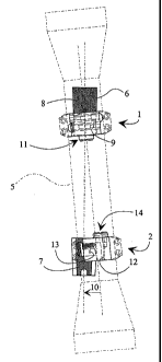
A rapid clamping base for an open rifle sights, the base consisting of two
clamping frames, a front frame (1) and a rear frame (2), whose clamping rings
(3,4) retain the sight (5). The frames can be clamped by means of a rapid
retainer to a two-piece clamping rail (6, 7) in a gun, such as a sporting gun.
The claws (8, 9) provided in the front frame (1) for engagement with the
clamping rail (6) are provided at differ- ent locations relative to the
longitudinal direction of the rail so as to be pressed in engagement with the
edges of the rail when the optic sight (5) is turned in the hori- zontal plane
from the lateral direction (10) to the central line of the gun. The front
frame (1) also comprises a support tongue (11) extending downwardly and
bearing against the rear edge of the front clamping rail (6). The rear frame
(2) comprises second claws (12, 13) engaging the clamping rail (7), one claw
(12) being solidly mounted in the rear frame and the other, i.e. the clamping
claw (13) being movable and in position to be pressed against the edge of the
rail. The rear frame (2) also comprises a support tongue (14) extending
downwards and bearing against the front edge of the rear clamping rail (7),
both of the frames thus having three pressing points on the clamping rails.


French Abstract

L'invention se rapporte à une base de serrage rapide pour un viseur ouvert d'arme rayée, constituée de deux cadres de serrage, d'un cadre avant (1) et d'un cadre arrière (2) dont les bagues de serrage (3, 4) maintiennent le viseur (5). Les cadres peuvent être serrés à l'aide d'un dispositif de retenue rapide sur un rail de serrage (6, 7) à deux pièces dans un fusil, notamment un fusil de sport. Des mâchoires (8, 9) prévues dans le cadre avant (1) pour être insérées dans le rail de serrage (6) se trouvent à différents emplacements par rapport au sens longitudinal du rail de manière à entrer en contact par pression avec les bords du rail lorsque le viseur optique (5) est tourné sur le plan horizontal de la direction latérale (10) vers la ligne centrale du fusil. Le cadre avant (1) comprend également une langue de support (11) s'étendant vers le bas et étant plaquée contre le bord arrière du rail de serrage avant (6). Quant au cadre arrière (2), il comprend des mâchoires (12, 13) en prise avec le rail de serrage (7), une mâchoire (12) étant montée à demeure dans le cadre arrière et l'autre mâchoire (13) pouvant être déplacée et se trouvant dans une position qui lui permet d'être plaquée contre le bord du rail. A l'instar du cadre avant (1), le cadre arrière (2) comprend une langue de support (14) s'étendant vers le bas et étant plaquée contre le bord avant du rail de serrage arrière (7), les deux cadres présentant trois points de pression sur les rails de serrage.

Claims

Note: Claims are shown in the official language in which they were submitted.


3

Claims

1. A rapid clamping base for an optic rifle sight, the base consisting of two
clamp-
ing frames, a front frame (1) and a rear frame (2), whose clamping rings (3,
4) retain
the optic sight (5) and which can be locked in engagement with a two-piece
clamp-
ing rail (6, 7) of a gun, such as a sporting gun, by means of a rapid
retainer, charac-
terised in that the claws (8, 9) provided in the front frame (1) for gripping
the
clamping rail (6) are provided at different locations relative to the
longitudinal di-
rection of the rail, so that the claws are pressed in engagement with the
edges of the
rail when the sight (5) is turned in the horizontal plane from the lateral
direction
(10) to the central line of the rifle, and that the front frame (1)
additionally com-
prises a downwardly extending support tongue (11), which bears against the
rear
edge of the front clamping rail (6), and that the rear frame (2) comprises
second
claws (12,, 13) engaging the clamping rail (7), one claw (12) being solidly
mounted
in the rear frame and the other, i.e. the clamping claw (13) being movable and
in
position to be pressed against the edge of the rail, and that the rear frame
also has a
downwardly extending support tongue (14), which bears against the front edge
of
the rear clamping rail (7), both of the frames thus having three pressing
points rela-
tive to the clamping rails.

2. A rapid clamping base as defined in claim 1, characterised in that the
clamping
claw (13) is spring-loaded so as to bear against the edge of the clamping rail
(7) un-
der the action of the spring force.

3. A rapid clamping base as defined in claim 1 or 2, characterised in that the
other
claw (8) of the front frame (1) is spring-loaded so that the claws (8, 9)
engage the
edges of the clamping rail (6) under the spring force when the optic sight is
turned
(10) in position.


Description

Note: Descriptions are shown in the official language in which they were submitted.


CA 02439797 2003-09-04
WO 02/070979 PCT/FI02/00168
1
Rapid clamping base for an optic rifle sight
The invention relates to a rapid clamping base for optic rifle sights, the
base consist-
s ing of two clamping frames, a front frame and a rear frame, whose clamping
rings
retain the sight and which can be locked to a two-piece clamping rail of a
gun, such
as a sporting gun, by means of a rapid retainer.
There are various locking systems operating with various technical solutions
includ-
ing conventional rapid clamping bases of this type. All these have the
inconven-
ience of the locking systems comprising some kind of female or male clamp mem-
ber, which can be fastened to the gun, usually on top of the barrel or to the
clamping
rail. When it is desirable to use an open sight, the optic sight is removed
using the
rapid retainer, however, the member fastened to the barrel will remain on
this,
which considerably hampers aiming operations or prevents them altogether. The
purpose of this invention is to eliminate this shortcoming. The rapid clamping
base
of the invention is characterised by the claws which are provided in the front
frame
to grip the clamping rail being provided at different locations relative to
the longitu-
dinal direction of the rail, so that the claws are pressed in engagement with
the
edges of the rail when the sight is turned in the horizontal plane from the
lateral di-
rection to the central line of the gun, and that the front frame additionally
comprises
a downwardly extending support tongue, which bears against the rear edge of
the
front clamping rail, and that the rear frame comprises second claws engaging
the
clamping rail, one of the claws being a stationary claw mounted in the rear
frame
and the other, i.e. the clamping claw, is movable and in position to be
pressed
against the edge of the rail, and that the rear frame also comprises a
downwardly ex-
tending support tongue, which bears against the front edge of the rear
clamping rail,
both the frames having three pressing points relative to the clamping rails.
The in-
vention thus allows an optic sight to be fastened and removed directly on the
clamp-
ing rail provided in the gun. No accessories hampering an open sight need to
be
fixed to the gun, nor are any other mechanical measures required.
A preferred embodiment of the invention is characterised by the clamping claw
be-
ing spring-loaded, so that the clamping claw bears against the edge of the
clamping
rail under the spring force. A second embodiment of the invention is
characterised
by one claw of the front frame being spring-loaded so as to engage the edges
of the
clamping rail under the action of the spring force when the sight is turned in
posi-
tion.


CA 02439797 2003-09-04
WO 02/070979 PCT/FI02/00168
2
The invention is described below by means of an example and with reference to
the
accompanying drawings, in which
figures 1-4 show the front frame of the rapid clamping base viewed from
different
directions,
figures 5-8 show the rear frame of the rapid clamping base viewed from
different
directions,
figure 9 is a top view of the fastening of the optic sight and
figure 10 shows the same as figure 9, but with the optic sight in retained
position.
The rapid clamping base of an optic rifle sight consists of two clamping
frames, a
front frame 1 and a rear frame 2. The clamping rings 3, 4 of the clamping
frames 1,
2 retain the optic sight 5. The frames can be fixed with a rapid retainer in
engage-
went with a two-piece clamping rail 6 of a gun, such as a sporting gun. The
claws 8,
9 provided in the front frame to engage the clamping rail 6 are provided at
different
locations relative to the longitudinal direction of the rail, so that the
claws are
pressed in engagement with the edges of the rail when the optic sight 5 is
turned in
the horizontal plane from the lateral direction to the central line of the
rifle as shown
with arrow 10. The front frame 1 also has a downwardly extending support
tongue
11, which bears against the rear edge of the front clamping rail 6. The rear
frame 2
comprises second claws 12, 13 engaging the clamping rail 7, one claw 12 being
sol-
idly mounted in the rear frame and the other, i.e. the clamping claw 13 being
mov-
able and in position to be pressed against the edge of the rail. The rear
frame 2 also
comprises a downwardly extending support tongue 14, which bears against the
front
edge of the rear clamping rail 7, both of the frames having three pressing
points on
the clamping rails. The clamping claw 12 is spring-loaded so as to bear
against the
edge of the clamping rail 7 under the action of the spring force, thus firmly
clamp-
ing the whole optic sight to the gun. The other claw 8 of the front frame 1 is
spring-
loaded so that the claws 8, 9 engage the edges of the clamping rail 6 under
the
spring force when the optic sight is turned 10 in position.

Representative Drawing
A single figure which represents the drawing illustrating the invention.
Administrative Status

For a clearer understanding of the status of the application/patent presented on this page, the site Disclaimer , as well as the definitions for Patent , Administrative Status , Maintenance Fee  and Payment History  should be consulted.

Administrative Status

Title Date
Forecasted Issue Date 2009-05-26
(86) PCT Filing Date 2002-03-05
(87) PCT Publication Date 2002-09-12
(85) National Entry 2003-09-04
Examination Requested 2007-02-06
(45) Issued 2009-05-26
Expired 2022-03-07

Abandonment History

There is no abandonment history.

Payment History

Fee Type Anniversary Year Due Date Amount Paid Paid Date
Application Fee $300.00 2003-09-04
Maintenance Fee - Application - New Act 2 2004-03-05 $100.00 2004-02-10
Registration of a document - section 124 $100.00 2004-07-29
Maintenance Fee - Application - New Act 3 2005-03-07 $100.00 2005-02-17
Maintenance Fee - Application - New Act 4 2006-03-06 $100.00 2006-02-10
Request for Examination $800.00 2007-02-06
Maintenance Fee - Application - New Act 5 2007-03-05 $200.00 2007-02-16
Maintenance Fee - Application - New Act 6 2008-03-05 $200.00 2008-02-14
Final Fee $300.00 2009-02-19
Maintenance Fee - Application - New Act 7 2009-03-05 $200.00 2009-02-26
Maintenance Fee - Patent - New Act 8 2010-03-05 $200.00 2010-02-23
Maintenance Fee - Patent - New Act 9 2011-03-07 $200.00 2011-02-25
Maintenance Fee - Patent - New Act 10 2012-03-05 $250.00 2012-02-07
Maintenance Fee - Patent - New Act 11 2013-03-05 $250.00 2013-02-07
Maintenance Fee - Patent - New Act 12 2014-03-05 $250.00 2014-02-26
Maintenance Fee - Patent - New Act 13 2015-03-05 $250.00 2015-02-12
Maintenance Fee - Patent - New Act 14 2016-03-07 $250.00 2016-02-08
Maintenance Fee - Patent - New Act 15 2017-03-06 $450.00 2017-02-13
Maintenance Fee - Patent - New Act 16 2018-03-05 $450.00 2018-02-09
Maintenance Fee - Patent - New Act 17 2019-03-05 $450.00 2019-02-21
Maintenance Fee - Patent - New Act 18 2020-03-05 $450.00 2020-02-20
Maintenance Fee - Patent - New Act 19 2021-03-05 $459.00 2021-02-24
Owners on Record

Note: Records showing the ownership history in alphabetical order.

Current Owners on Record
SAKO OY
Past Owners on Record
AALTO, JUHA
KUPARINEN, KARI
Past Owners that do not appear in the "Owners on Record" listing will appear in other documentation within the application.
Documents

To view selected files, please enter reCAPTCHA code :


To view images, click a link in the Document Description column. To download the documents, select one or more checkboxes in the first column and then click the "Download Selected in PDF format (Zip Archive)" or the "Download Selected as Single PDF" button.

List of published and non-published patent-specific documents on the CPD .

If you have any difficulty accessing content, you can call the Client Service Centre at 1-866-997-1936 or send them an e-mail at CIPO Client Service Centre.


Document
Description 
Date
(yyyy-mm-dd) 
Number of pages   Size of Image (KB) 
Abstract 2003-09-04 2 71
Claims 2003-09-04 1 50
Drawings 2003-09-04 4 63
Description 2003-09-04 2 127
Representative Drawing 2003-09-04 1 13
Cover Page 2003-11-04 2 50
Representative Drawing 2009-05-05 1 8
Cover Page 2009-05-05 2 52
PCT 2003-09-04 6 266
Assignment 2003-09-04 3 89
Correspondence 2003-10-31 1 26
Fees 2004-02-10 1 35
Assignment 2004-07-29 3 114
Fees 2005-02-17 1 36
Fees 2006-02-10 1 34
Fees 2007-02-16 1 33
Prosecution-Amendment 2007-02-06 1 29
Correspondence 2009-02-19 1 35