Note: Descriptions are shown in the official language in which they were submitted.
CA 02439821 2008-06-25
HYBRID SPACE FRAME FOR MOTOR VEHICLE
Field of the Invention
The present invention is generally related to motor vehicle frames and
more particularly to motor vehicle space frames constructed using
hydroformed members.
Background of the Invention
Tubular hydroforming is increasingly used in vehicle frame
construction because tubular hydroforming offers automobile manufacturers
many commercial advantages. The use of tubular hydroforming enables
manufacturers to better control frame stiffness, dimensional stability,
fatigue
in life, and vehicle crashworthiness over prior vehicle designs while reducing
frame mass and cost.
Hydroforming is a metal-forming process in which high-pressure fluid
is used to outwardly expand a tubular metal blank into conformity with the
surfaces of a die cavity of a die assembly to form an irregularly shaped
tubular part. Hydroformed members can be provided with a wide range of
geometries in comparison with other methods of forming parts. Each
hydroformed frame member can be constructed to have a cross-sectional
configuration that varies continuously along its length, to the configuration
desired and each frame member can be constructed to curve or "bend" along
its length to defme different frame parts such as frame side rails and frame
pillars. An example of a hydroformed space frame that is generally known in
the art may be found in U.S. Patent 6,092,865, issued to Jackel, et al.
Depending on specific circumstances, certain "sharp" bends may not be
advantageous or possible due to particular space constraints for certain motor
vehicle designs. Space frames are cage-like structures on which other vehicle
components, including the engine, drive train, suspension and the hang-on
vehicle body parts, can be mounted. Tubular hydroformed space frames may
be used in the construction of relatively large vehicles such as sports
utility
vehicles and larger
1
CA 02439821 2008-06-25
sedans and trucks. In relatively larger frame vehicles, angular limitations on
the construction on tubular hydroformed members generally pose few
problems. However, the limited space available in some motor vehicles such
as compact or other smaller frame cars can limit the use of hydroformed
space frames therein. This is especially true when the motor vehicle has set
interior and exterior configurations and the frame must be fit between the
two.
There is a need for a vehicle space frame that can provide the benefits
of tubular hydroformed construction for smaller frame vehicles with limited
frame space.
Summary Of The Invention
To meet the needs expressed above, the present invention provides
space frame for a motor vehicle that includes a pair of tubular, hydroformed
longitudinally extending lower side rail members and a pair of tubular,
hydroformed upper longitudinal members. Each of the upper longitudinal
members includes a rear pillar-forming portion and a rail-forming portion,
each of the pillar-forming portions being coupled to an end of a respective
one of the lower side rail members and extending upwardly therefrom to
define a rearward-most pillar of the motor vehicle and each of the rail-
forming portions extending forwardly from the pillar-forming portion to
define a roof support rail of the motor vehicle. The space frame further
includes a pair of forward-most pillar assemblies, each of the pair of forward-
most pillar assemblies being coupled to a respective one of the pair of lower
side rail members and extending upwardly therefrom and being coupling with
a respective one of the upper longitudinal members, and each of the forward-
most pillar assemblies being formed from stamped sheet metal. A laterally
extending connecting structure is mounted between the pair of lower side rail
members, the connecting structure being constructed and arranged to hold the
pair of lower side rail members in laterally spaced relation to one another.
The invention further provides space frame for a motor vehicle
comprising a pair of tubular, hydroformed longitudinally extending lower
side rail members and a pair of tubular hydroformed upper longitudinal
members. Each of the upper
2
CA 02439821 2003-08-29
WO 02/070322 PCT/US02/06051
longitudinal members includes a rear pillar-forming portion and a rail-forming
portion, each pillar-forming portion being coupled to an end of a respective
one of
the lower side rail members and extending upwardly therefrom to define a
rearward-
most pillar of the motor vehicle and each of the rail-forming portions
extending
forwardly from the rear pillar-forming portion to define a roof support rail
of the
motor vehicle. The space frame further includes pair of pillar support
structures,
each pillar support structure being of stamped sheet metal construction and
each
being connected to a respective lower side rail member at the location to
support a
forward-most pillar structure. The space frame also includes a pair of forward-
most
1o pillar structures, each pillar structure being coupled at a lower end
thereof to an
associated pillar support structure and being coupled at an upper end thereof
to an
associated upper longitudinal member. A laterally extending connecting
structure is
mounted between the pair of lower side rail members, the connecting structure
being
constructed and arranged to hold the pair of lower side rail members in
laterally
spaced relation to one another.
Other objects, features, and advantages of the present invention will become
apparent from the following detailed description, the accompanying drawings,
and
the appended claims.
Brief Description of the Drawings
FIGS. 1-4 show various stages of assembly of an exemplary vehicle
illustrating an embodiment of the invention, FIGS. 1-4 particularly showing
the
assembly of a space frame of the vehicle and showing various body panels
mounted
to the space frame;
FIG. 1 illustrates an embodiment of the present invention including a lower
frame assembly of the space frame in isolation;
FIG. 2 shows the lower frame assembly of FIG. 1 with various body panels
secured thereto;
FIG. 3 shows the frame assembly of FIG. 2 with an upper frame assembly
mounted thereto;
3
CA 02439821 2003-08-29
WO 02/070322 PCT/US02/06051
FIG. 4 shows the space frame of FIG. 3 with additional body panels
structures mounted thereto;
FIG. 5 is an isolated view of a hydroformed portion of the assembled space
frame of Figs. 1-4 with stamped sheet metal portions thereof removed and not
shown;
FIG. 6 is an exploded view of a forward-most pillar assembly of the space
frame of Figs. 1-4;
FIG. 7 is a cross sectional view taken through the 7-7 as indicated in FIG. 4;
FIG. 8 is a cross sectional view taken through the 8-8 as indicated in FIG. 4;
FIG. 9 is an exploded view of a pillar support structure of the space frame of
Figs. 1-4;
FIG. 10 is an assembled view of a pillar support structure on of the space
frames of Fig. 1-4;
FIG. 11 is an exploded view of a portion of the space frame in the vicinity of
a joint formed between a B pillar of the space frame and a side rail member of
the
space frame of Figs. 1-4;
FIG. 12 is a cross sectional view taken through 12-12 as indicated in FIG. 4;
FIG. 13 is a cross sectional view taken through 13-13 as indicated in FIG. 4,
and additionally illustrating a door and door seal;
FIG. 14 is a cross sectional view taken through 14-14 as indicated in FIG. 4;
FIG. 15 is a cross sectional view taken through 15-15 as indicated in FIG. 4;
FIG. 16 is a cross sectional view taken through 16-16 as indicated in FIG. 4;
FIG. 17 is a cross sectional view taken through 17-17 as indicated in FIG. 4
and additionally illustrating a door and door hinge assembly;
FIG. 18 is a cross sectional view taken through 18-18 as indicated in FIG. 4
and additionally illustrating a door seal attached to the C-pillar;
FIG. 19 is a cross sectional view taken through 19-19 as indicated in FIG. 4
and additionally illustrating a partial, cross-sectional view of the vehicle
lift gate and
its associated pivot mechanism;
FIG. 20 is an exploded view of a portion of the space frame of FIGS. 1-4
showing an upper longitudinal member of the space frame and a roof rail outer
4
CA 02439821 2003-08-29
WO 02/070322 PCT/US02/06051
structure mounted thereon in fragmentary view and showing various components
that are mounted to the space frame in the vicinity of a transition between a
roof rail
portion of the upper longitudinal member and a pillar forming portion of the
upper
longitudinal member in fragmentary view;
FIG. 21 is a cross sectional view taken through 21-21 as indicated in FIG. 4;
FIG. 22 is an exploded view of portions of the space frame of Figs. 1-4 and
components mounted thereto in the vicinity of a joint between the roof rail
portion
of the upper longitudinal member and a cross member of the space frame;
FIG. 23 is a cross sectional view taken through 23-23 as indicated in FIG. 4
and illustrating a portion of a vehicle door;
FIG. 24 is a cross sectional view taken through 24-24 as indicated in FIG. 4;
FIG. 25 is a cross sectional view taken through 25-25 as indicated in FIG. 4;
and
FIG. 26 is a schematic view of a tubular hydroforming die assembly showing
a blank mounted therein for forming certain members found in the frame of
FIGS. 1-
4.
Detailed Description of the Invention
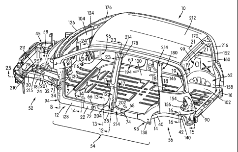
FIGS. 1-4 show various stages of assembly of an illustrated embodiment of
the invention in the form of a motor vehicle space frame. The space frame 10
is
generally illustrated with a plurality of body panels mounted thereto. Vehicle
space
frames for any size vehicle may be constructed utilizing the principles of
vehicle
construction taught by the illustrated embodiment. The space frame 10 is
particularly well-suited for the construction of a compact, sub-compact, or
smaller
commercial motor vehicles (generally referred to as "smaller frame vehicles"
in the
present application). As will become apparent, the space frame 10 utilizes a
significant amount of tubular hydroformed construction to allow the vehicle
manufacturer to have the advantage of the benefits offered by tubular
hydroformed
technology (such as reduction of frame weight without compromising vehicle
crashworthiness, reduction of the total number of frame parts and of the
number of
welds required for frame assembly, reduction in the amount of waste generated,
and
5
CA 02439821 2003-08-29
WO 02/070322 PCT/US02/06051
so on) and utilizes non-hydrofoming construction, such as stamping, to
optimize the
amount of tubular hydroformed construction that can be incorporated into the
smaller frame vehicle. These advantages will become apparent as the
construction
on the space frame 10 is considered in detail. Hydroformed space frames are
generally known as in U.S. Patent No. 6,092,865 to Jaekel et al., which is
incorporated herein by reference, in its entirety.
FIG. 1 shows a lower frame assembly 12 of the space frame 10 in isolation.
The lower frame assembly 12 includes a pair of longitudinally extending,
laterally
spaced lower side rail members 14, 16 of tubular hydroformed construction.
Because the lower side rail members 14, 16 are of mirror image construction,
only
rail member 14 will be discussed in detail, but the discussion applies equally
to rail
member 16. Corresponding portions of rail members 14 and 16 are labeled with
identical reference numbers in the present application to facilitate
discussion of the
invention, but it is understood that these corresponding portions are of
mirror image
construction.
Rail member 14 is of three-piece construction and includes a tubular
hydroformed forward rail portion 18, a central rail portion 20 and a rearward
portion
22. These portions 18, 20, 22 are telescopically interengaged and welded
together at
joints 24 and 26, respectively.
The forward portion 18 of rail member 14 includes a forward "crash tip"
section 28 and a relatively straight, longitudinally extending rearward
section 30.
The central portion 20 of rail member 14 includes a relatively straight,
longitudinally
extending forward section 32, and generally outwardly angled (in the
longitudinal
front to rear vehicle direction) intermediate section 34 and a longitudinally
extending, relatively straight rearward section 36. The rearward rail portion
22
includes a longitudinally extending, relatively straight forward section 38,
an
inwardly (in the longitudinal front to rear vehicle direction) angled
intermediate
section 40, and a longitudinally extending, relatively straight rearward
section 42.
A bumper assembly 45, which can be of stamped sheet metal construction, is
mounted on the forwardmost ends of the rail members 14, 16. The crash tip
section
28 of rail member 14 is constructed and arranged to absorb impact in the event
of a
6
CA 02439821 2003-08-29
WO 02/070322 PCT/US02/06051
vehicle head on collision. A pillar support structure 44, 46, which can be of
stamped sheet metal construction, is connected to the exterior surface of a
rail
member 14 or 16, respectively, by welding or other suitable method, generally
in the
area of transition between sections 34 and 36 thereof. Because the pillar
support
structures 44, 46 are of mirror image construction, only structure 44 will be
considered in detail, but the discussion applies equally to structure 46.
Corresponding portions of the structures 44, 46 are labeled with identical
reference
numerals even though they are of mirror image construction. The pillar support
structure 44 includes an inner support element 48 and an outer support element
50.
The forward sections 30, 32, 34 of the rail member 14 and the inner support
element 48 of the support structure 44 generally define a front wheel well 52.
The
outer support element 50 on the support structure 44 and the straight
longitudinally
extending sections 36 and 38 of the rail member 14 generally define a rocker
panel
portion 54 of the lower frame assembly 12. The rearward sections 40 and 42 of
the
rail member 14 generally define a rear wheel well 56. The forward sections 30,
32,
34 of the rail members 14, 16 generally define an engine compartment area 58
of the
lower frame assembly 12. Similarly, sections 36 and 38 of the rail members 14,
16
generally define a passenger compartment area 60 of the assembly 12 and
sections
40 and 42 of the rail members 14, 16 generally define a rear cargo area 62 of
the
frame assembly 12.
A plurality of laterally extending connecting structures generally designated
64 are connected between the lower side rail members 14, 16 and are
constructed
and arranged to hold the same in laterally spaced fixed relation to one
another. The
connecting structure 64 includes a pair of first and second central connecting
members 66, 68 (which have closed cross sections and which may be, for
example,
of hydroformed or roll formed construction) and third central connecting
structure
70. The third connecting structure 70 has an open, essentially C-shaped cross
section and may be of the stamped sheet metal construction. Opposite ends of
the
connecting members 66, 68 are secured to the rails 14, 16 at joints 72, 74,
respectively. Joints 72 and 74 are essentially identical in construction and
are
formed by cutting holes in opposing walls of each of the rail members 14, 16
and
7
CA 02439821 2003-08-29
WO 02/070322 PCT/US02/06051
securing opposite ends of the connecting members 66, 68 in respective pairs of
openings by welding. The connecting member 70 is connected between the rail
members 14, 16 by welding opposite ends of the member 70 to exterior surface
portions of the respective rail members 14, 16.
A pair of the inwardly spaced, longitudinally extending rail members 76, 78
are connected between the angled sections 34, 40, respective, of the rail
members
14, 16. Because the inner rail members 76, 78 are of mirror image construction
only
rail member 76 will be discussed in detail but the discussion applies equally
to rail
member 78. The rail member 76 is preferably of stamped, open cross section
sheet
metal construction and has an open, essentially C-shaped cross section.
Preferably
the rail member 76 is secured to the lower frame assembly 12 by welding
opposite
ends of the member 76 to inwardly facing exterior wall surfaces on sections 34
and
40, respectively, of the rail member 14. The laterally extending members 66,
68, 70
are secured by welding or by other suitable method in notches 80, 82, 84,
respectively, formed in the longitudinally extending rail member 76.
The cross structure 64 further includes a pair of rearward connecting
structures 86, 88. Each rearward connecting structure 86, 88 preferably has an
open,
essentially C-shaped cross section and is a sheet metal structure that has
been shaped
by stamping. The connecting structure 86 is secured to the frame assembly 12
by
securing opposite ends thereof to inwardly facing exterior surfaces of the
inner rail
members 76, 78 by welding or other suitable method. The connecting structure
88 is
secured to the frame assembly 12 by welding opposite ends thereof to inwardly
facing exterior surfaces of opposing sections 42 of the rail members 14, 16. A
rearward most connecting member 90 is secured between the rail members 14, 16
at
joints 92. Preferably the connecting member 90 is of tubular construction
(i.e., has a
close cross-section) and may be formed by hydroforming, by roll forming or any
other appropriate method. Joints 92 are similar in construction to joints 72
(see FIG.
15 for a cross sectional view of joint 92).
As shown in FIGS. 2-4, a plurality of the vehicle components, each can be
formed from non-hydroforming methods such as of stamped, sheet metal
construction, are secured to the lower frame assembly 12. These components
8
CA 02439821 2003-08-29
WO 02/070322 PCT/US02/06051
include floor pan structures, a pair of forward-most pillar assemblies 94, 96
and a
pair of rear pillar support assemblies 98, 99. More specifically, the central
floor pan
structure 100 is secured to intermediate portions of the rail members 14, 16
and to
portions of the cross members 66, 68, 70 and 86, by welding or other
appropriate
method. A rear floor pan 102 is secured to rearward portions of the rail
members
14, 16 and to cross members 88 and 90 by welding or other appropriate method.
The floor pans 100, 102 can be of stamped sheet metal construction and provide
the
floor structure for the passenger compartment 60 and the cargo compartment 62,
respectively.
A lower portion of a dash panel 104, which can be of stamped sheet metal
construction, is welded to the lower frame assembly 12 at the forward end of
the
passenger compartment area 60. The dash panel 104 supports various vehicle
structures in the assembled vehicle including an instrument panel (not shown),
a
lower portion of a vehicle windshield (not shown) and various vehicle controls
and
also functions as a firewall between the passenger and engine compartments.
The construction of the forward-most pillar assembly 94 and the manner in
which the pillar assembly 94, the side rail member 14, the pillar support
structure 44
and the dash panel 104 are interconnected can be appreciated from FIGS. 6-8.
The
pillar assemblies 94, 96 part of mirror image construction. Only assembly 94
will be
discussed in detail, but the discussion applies equally to the assembly 96.
The forward-most pillar assembly 94 is a multi-piece assembly of stamped
sheet metal structures that provides the space frame 10 with a forward-most or
A
pillar and provides support and attachment structure for a hydroformed roof
rail 106
(shown in fragmentary view, for example, in FIG. 6) of the tubular hydroformed
upper frame assembly described below. The construction of the pillar assembly
94
is best understood from the exploded view of FIG. 6. FIG. 6 shows in
fragmentary
view the central portion 20 of the rail member 14 in exploded relation with
the
rearward portion 20 to thereof. The telescopic nature of the inter-engagement
of
joint 26 can be appreciated from the exploded view of FIG. 6. An outer edge
108 of
a lower, essentially horizontally extending wall portion 110 of the inner
support
element 48 of the pillar support structure 44 is welded to a downwardly facing
9
CA 02439821 2008-06-25
surface of the rail member 14 generally in the vicinity of transition between
a
rocker panel-forming section 36 of the rail member 14 and the angled section
34 of the rail member 14. An essentially vertical wall portion 112 of the
inner
support element 48 of the pillar support structure 44 defines the rearward
extent
of the front wheel well 52. The outer support element 50 of the pillar support
structure 44 is secured to the inner support element 48 preferably by welding
to
form a box-like support structure generally between the rocker panel portion
of
the side rail member 14 (i.e., sections 36 and 38 thereof) and the front wheel
well to support the forward-most pillar assembly 94. The outer element 50
provides a forward portion of the rocker panel 54. The support structure 44
provides a support for inner and outer pillar members 114, 116, respectively,
of
the pillar assembly 94. The inner and outer pillar members 114, 116 provide a
pillar structure for the space frame 10 the defines the A pillar. The inner
and
outer pillar members 114,116 thus form the vehicle A pillar and provide
attachment structure for the tubular hydroformed roof rail 106 to the A
pillar.
The inner and outer pillar members 114, 116 can be stamped sheet metal
structures that are preferably secured to one another and to the surrounding
stamped sheet metal and tubular hydroformed components by welding,
although any appropriate method can be used to secure these structures to one
another.
A lower portion 118 of the inner pillar 114 is welded within the box-like
pillar support structure 44 (see the cross section of FIG. 8). An intermediate
portion 120 of the inner pillar member 114 is secured to an edge of the dash
panel 104. A reinforcement structure 121, can be of stamped sheet metal
construction and may be welded in reinforcing relation between the dash panel
104 and the inner pillar member 114. An upper portion 122 of the inner pillar
member 114 is secured to an upper edge of the dash panel 104 and to upper and
lower plenum structures 124, 126, respectively.
A lower portion 128 of the outer pillar member 116 is secured to the
exterior of the outer support element 50 of the pillar support structure 44
and to
a portion of the side rail member 14 and an upper portion 130 of the outer
pillar
member 116 is secured to the inner pillar member 114 in the assembled vehicle
space frame 10.
CA 02439821 2003-08-29
WO 02/070322 PCT/US02/06051
The roof rail portion 106 of a tubular hydroformed member is generally secured
therebetween. FIG. 2 shows the pillar support member 44, the inner pillar
member
114, the dash panel 104 and the upper and lower plenum structures 124, 126
mounted on the lower frame assembly 12.
FIG. 2 also shows the pillar support assemblies 98, 99 mounted on the lower
frame assembly 12. The pillar support assemblies 98, 99 are of similar
construction
and may be of mirror image construction. The structure of pillar support
assembly
98 is considered in detail and the construction of pillar support assembly 99
is
briefly discussed and can be understood from the discussion of assembly 98.
The pillar support assembly 98 is shown in exploded view in FIG. 9. FIG. 9
shows the portion of the rail member 14 that defines the rear wheel well 56 in
fragmentary view. The pillar support assembly 98 includes a rear wheel house
structure 132, a rear quarter panel inner structure 134, an inner pillar
support
structure 136, an outer pillar support structure 138 and an outer rear quarter
panel
structure 140.
A lower edge 142 of the rear wheel house structure 132 is welded to sections
40 and 42 of the rail member 14. A lower portion of the rear wheel house
structure
132 defines a portion of the rear wheel well 56. The rear quarter panel inner
structure 134 is secured to the wheel house structure 132 and to a rearward
portion
of the rail member 14 (see, for example, FIG. 2), preferably by welding. The
inner
pillar support structure 136 is secured to the rail member 14, the rear wheel
house
structure 132 and to the rear quarter panel inner structure 134, preferably by
welding. As shown, for example, in FIG. 4, the inner pillar support structure
136
includes support structure 144, which can be shaped by stamping, to receive a
lower
end portion of the tubular hydroformed member 146 (shown in fragmentary view
in
FIG. 9) that provides a C pillar for the space frame 10. The outer pillar
support
structure 138 is secured to a portion of the rail member 14 and to a portion
of the
inner pillar support structure 136, preferably by welding. The outer pillar
support
structure 138 includes stamped structure 148 that is constructed and arrange
to
support the tubular hydroformed C pillar 146. Structures 134, 136, and 138 can
all
be made of non-hydroforming methods, such as stamped sheet metal construction.
11
CA 02439821 2003-08-29
WO 02/070322 PCT/US02/06051
Optionally, a pair of weld openings 150 may be provided in the outer pillar
support structure 138 to help secure the C pillar 146 to the support structure
138.
The outer rear quarter panel structure 140 is welded to portions of the inner
and
outer pillar support structures 136, 138, to the rear quarter panel inner
structure 134,
to the C pillar 146 and to the adjacent D pillar 152 (see, for example, FIG.
4). It can
also be appreciated from FIG. 4 that the rear quarter panel inner and outer
structures
134, 140 are each provided with openings 154, 156 to accommodate vehicle tail
lights.
The partially assembled pillar support assembly 99 is shown in enlarged
view in FIG. 10. The pillar support assembly 99 includes a rear wheel house
structure 158, a rear quarter panel inner structure 160, an inner pillar
support
structure 162 and an outer pillar support structure 164. As shown in FIG. 10,
the
inner and outer pillar support structures 162, 164 cooperate to receive and
support a
lower portion of a C pillar 146 of the space frame 10. A portion of the rear
quarter
panel inner structure 160 is connected to the rear pillar 152, to the inner
pillar
support structure 162 and to the C pillar 146 which helps hold the C pillar
146
rigidly in place.
It can be appreciated from a comparison of FIGS. 2-4 that the space frame 10
may be constructed by mounting the floor pans 100, 102, the dash panel 104,
the
pillar support structures 44, 46 the inner pillar members 114, the upper and
lower
plenum structures 124, 126, the rear wheel house structures 132, 158, the rear
quarter panel inner structures 134, 160, the inner pillar support structures
136, 162
and the outer pillar support structures 138, 164 to the lower frame assembly
12 (as
shown in FIG. 2).
At this point in the construction, a tubular hydroformed upper frame
assembly generally designated 170 may be mounted on the vehicle frame. The
upper frame assembly 170 includes a pair of tubular hydroformed upper
longitudinal
members 174, 176, a first tubular hydroformed U-shaped member 178 and a second
tubular hydroformed U-shaped member 180.
The upper longitudinal members 174, 176 are of mirror image construction
so only upper longitudinal member 174 will be discussed in detail, but the
12
CA 02439821 2003-08-29
WO 02/070322 PCT/US02/06051
discussion applies equally to member 176. Each of the longitudinal members 174
includes a D pillar forming portion 152 and a roof rail forming portion 106.
The
pillar forming portion 152 of the upper longitudinal member 174 is connected
at a
free end to the side rail member 14 at joint 186 and extends upwardly
therefrom to
define the rearward most or D pillar of the space frame 10. The rail forming
portion
106 of the upper longitudinal member 174 extends forwardly from the pillar
forming
portion 152 thereof to define the roof rail of the space frame 10. The upper
longitudinal member 174 is preferably hydroformed from a single tubular blank
that
includes a butt weld 188. It is preferred to construct the upper longitudinal
member
174 in one hydroforming operating to minimize stacked tolerances in the
longitudinal vehicle direction.
The first and second U-shaped members 178, 180 can both be of one-piece,
tubular hydroformed construction. Members 178 and 180 each include cross
portions 190, 192, respectively, and a pair of legs 194, 146, respectively,
that
extends integrally from junctures 198, 200, respectively, at opposite ends of
the
respective cross portions 190, 192.
The free end of each leg 194 of the first U-shaped member 190 is secured
within an upwardly facing opening 202 formed in the respective rail members
14, 16
to form joints 204. The roof rail 106 is welded in surface-to-surface relation
to the
cross member 190 at the juncture 198 thereof to form a joint 206. The legs 194
of
the first U-shaped cross member 190 define a pair of B pillars of the space
frame 10.
Similarly, the roof rail 106 is welded in overlying surface-to-surface
relation
to the juncture of the second cross member 192 to form joint 208 and the free
ends
of the legs 146 of the second cross member 192 are supported by and are welded
within the structures 144 and 148 (see FIG. 9) of the inner and outer pillar
support
structures 136, 138, respectively.
As can be appreciated from a comparison of FIGS. 3 and 4, the outer pillar
member 116 may be welded to the pillar assembly 94 after the tubular
hydroformed
upper frame assembly 170 is assembled to the space frame. A stamped outer
support 210 (see FIG. 4) is secured to the pillar assembly 98 and extends
generally
forwardly therefrom. The outer support 210 includes an inner portion 211 that
is
13
CA 02439821 2003-08-29
WO 02/070322 PCT/US02/06051
secured to the inner pillar member 114 and an outer portion 215 that is
secured to
the outer pillar member 116. The outer support 210 may be of stamped sheet
metal
construction and may be secured to the pillar assembly 98 by welding. The
outer
support 210 can be used to mount the vehicle fender and other body structures.
A roof panel 212, the outer rear quarter panel structures 140 and a plurality
of door seal interface structures, generally designated 214, are mounted on
the
vehicle frame as shown, for example, in FIG. 4. A roof panel outer structure
216,
which can be of stamped sheet metal construction, is mounted on each side of
the
vehicle along the roof rail 106 thereof and then downwardly along an upper
portion
of the D pillar 152 to the outer quarter panel structure 140.
FIG. 7 shows that the inner and outer pillar members 114, 116 are welded
together along seams 215, 217 and are shaped to provide the A pillar with a
closed
cross section. FIG. 8 is a cross sectional view showing the manner in which
the
inner and outer pillar members 114, 116, the inner and outer support elements
48, 50
and the dash panel 104 are secured together. Specifically, the outer pillar
member
116, the outer support element 50 and the inner support element 48 are welded
together along seam 219. The outer support element 50, the inner pillar member
114
and the dash panel 104 are welded together along seam 221. FIG. 14 shows that
the
outer pillar member 116 and the floor pan 100 are welded together along seam
223.
The outer pillar member 116 and the floor pan 100 may also be welded to the
rail
member 14 by single sided spot welds (shown schematically) as at 225.
FIG. 11 shows an exploded view of joint 204 and of two of the door seal
interface structures 214. The opening 202 for the C pillar and a weld opening
218
may be laser cut in the side rail member 14. FIG. 12 shows the assembled joint
204
in cross-sectional view. The pillar, the side rail member 14, the door seal
interface
structure 214 and the floor pan 100 may be secured together by a series of
welds,
such as MIG welds, (shown schematically) as at 220 and a series of welds, such
as
single side spot welds (shown schematically) as at 222. A door seal 224 (see
FIG.
13) is mounted on the transition structure 214 in the assembled the vehicle
and is
positioned to engage a vehicle door 226 when the door 226 is in its closed
position
to seal the door.
14
CA 02439821 2003-08-29
WO 02/070322 PCT/US02/06051
FIG. 15 shows construction of the space frame 10 the area of joint 92 and
186. Joint 92 is formed by inserting the tubular connecting member 90 through
openings 228, 230 formed in opposite sides of the rail member 14 and welding
the
members 90, 14 together. Joint 186 is formed by cutting and removing several
wall
portions at a free end of the pillar portion 152 of the upper longitudinal
member 174,
placing the pillar portion 152 into contact with the exterior surface of the
rail
member 14 and welding the structures together. A rear pillar seal transition
structure 232 is welded between a lower end of the pillar portion 152 of the
upper
longitudinal member 174 and an upper member 234 mounted on an upper surface of
the rear cross member 90. The transition structure 232 forms a rounded corner
of
the rear opening 235 into the cargo compartment of the vehicle space frame 10.
The
structure 232 and the member 234 are preferably each metal structures that
have
been shaped by stamping and welded to the space frame 10.
FIG. 16 is a cross-sectional view showing the manner in which the rear
wheel house structure 132 and the floor pan 102 in the cargo compartment are
mounted to the rail member 14 and to each other. The wheel house structure 132
includes a downwardly extending flange 236 that is secured by welding to the
rail
member 14 as, for example, by a series of single sided spot welds (not shown).
The
cargo floor pan 102 is welded to an upper surface of the rail member 14 and to
an
upper the facing surface of the wheel house structure 132.
FIG. 17 shows a cross-sectional view of the B pillar. The B pillar has a
tubular hydroformed construction. Outwardly facing surfaces 240 and 242 define
seal engaging planes for a door seal (not shown in FIG. 17). An internally
threaded
hinge attachment sleeve 244 is inserted into the B pillar to receive a hinge
bolt 246
to attach hinge 248 for a vehicle door 249. The C pillar is shown in cross-
section in
FIG. 18. The C pillar has a tubular hydroformed construction and defines a
outwardly facing seal plane 250 for door sea1252.
FIG. 19 shows a cross-sectional view through the D pillar and shows a cross-
sectional view of the roof panel outer 216. The roof panel outer 216 is
attached to
an upper prop rod attachment bracket 256 another along seam 258. The roof
panel
outer 216 is welded to the D pillar at seam 260 and the attachment bracket 256
is
CA 02439821 2003-08-29
WO 02/070322 PCT/US02/06051
welded to the D pillar at 262. The bracket 256 serves as a pivotal point of
attachment for a gas stroke assembly 264 (shown schematically) than is mounted
to
a vehicle liftgate 266 (shown in fragmentary view in FIG. 19).
FIG. 20 shows the details of the construction of the space frame 10 in the
vicinity of the transition between the pillar forming portion 152 and the roof
rail
forming portion 106 of the upper longitudinal member 176. The space frame 10
includes the roof panel 212, a liftgate hinge reinforcement structure 268, a D
pillar
header 270, and a roof rail to header bracket 272. FIG. 20 also shows the
manner in
which the roof panel outer 216 (also called the class "A" roof rail) is
mounted to the
upper longitudinal member 174. FIG. 21 shows the details of the manner in
which
the D pillar header 270 is secured to the roof panel 212. The header 270 is
welded
to the roof panel 212 along seam 271.
FIG. 22 shows an exploded view of the structure of the space frame 10 in the
vicinity of the joint 206 between the roof rail portion 106 of the upper
longitudinal
member 174 and the first cross member 190. FIG. 22 shows the roof panel 212,
the
roof rail portion 106 of the upper longitudinal member 174, the cross member
190, a
door seal transition structure 214 and the roof rail outer 216. FIG. 23 shows
the
manner in which these structures are related in the assembled space frame 10.
Specifically, the roof rail portion 106 is welded in surface-to-surface
relation to the
juncture 198 of the cross member 190. The door seal transition structure 214
is
welded to the roof rail portion 106 of the upper longitudinal member 174 and
to a
portion of the cross member 190. The roof rail outer 216 is welded to the
transition
structure 214 at 276 and to the roof rail portion at 278. The roof panel 212
is welded
to the roof rail outer 216 at 278. A vehicle door 279 is shown in fragmentary
view.
FIG. 24 is a cross sectional view through the roof rail portion 106 of the
upper longitudinal member 174 showing a windshield header attachment structure
280 and the roof rail outer 216 welded to the roof rail portion 106 of the
upper
longitudinal member 174.
FIG. 25 shows in cross-sectional view the structure of the bumper assembly
45 and the manner in which the same is mounted to the rail member 14.
Specifically, the bumper assembly 45 includes an arcuate inner bumper element
284
16
CA 02439821 2003-08-29
WO 02/070322 PCT/US02/06051
and an outer bumper element 286 welded thereto. A bumper attachment structure
290 is welded to the inner bumper element 284. A pair of bumped connecting
members 292, 294 are welded between the attachment structure 290 and the
forwardmost end of the rail member 14 to attach the bumper assembly 45 to the
side
rail member 14. An attachment bracket 296 is secured between an outer portion
of
the bumper element 284 and a side portion of the rail member 14.
Because many of the structural features of each hydroformed member are
formed during a hydroforming operation that creates the same, a preferred
method of
hydroforming the tubular hydroformed components of the space frame 10 will be
considered. A preferred hydroforming operation for forming the hydroformed
support member 10 can be understood from FIG. 26. An example of a
hydroforming operation will be given using member 190. Each hydroformed
member, such as hydroformed U-shaped member 190, may be formed from a
tubular blank 302. The blank 302 is constructed of a suitable metallic
material and
has a closed transverse cross section and open tubular ends. Preferably, the
blank
302 is constructed of a suitable grade of steel. Each blank 302 may be formed
by
any suitable method. For example, a continuous strip of metallic material may
be
shaped by roll forming and seam welding to have a closed transverse cross
section.
Alternatively, a continuous length of metallic tubing may be formed by
extrusion.
2o The continuous tubular structure may then be cut to the length required to
form a U-
shaped member 190.
The blank 302 is preferably bent into a "U" shape prior to being placed in a
hydroforming die assembly. Each leg portion of the member 302 preferably forms
relatively sharp angle with the central cross portion thereof. Because the
angle in
the U-shaped member 190 is relatively "sharp" (that is, at an angle greater
than 30 ),
these angles require relatively sharp bends in the blank 302. Preferably the
present
invention bends the blank 302 according the teachings of U.S. Patent No.
5,953,945
entitled METHOD AND APPARATUS FOR WRINKLE-FREE
HYDROFORMING OF ANGLED TUBULAR PARTS, which is hereby
incorporated herein by reference in its entirety. The teachings of the '945
patent
reference can be used to avoid wrinkle formation during the bending operation,
17
CA 02439821 2003-08-29
WO 02/070322 PCT/US02/06051
particularly on the concave portion of each bend in a hydroformed part. A
blank
302 may be bent in a computer numeric controlled ("CNC") bending machine prior
to being placed in the die assembly or, alternatively, may be bent by stretch
bending
to achieve the "U" shape. The U-shaped blank 302 includes an essentially
straight,
longitudinally extending central portion and a pair of legs extending from
opposite
ends of the central portion. The juncture or "elbow" formed between the
central
portion and each leg defines a concave exterior surface portion on one side
thereof
and a convex exterior surface portion on an opposite side thereof. A suitable
lubricant may be applied to the exterior of the blank 302 prior to placing it
in the die
assembly.
With reference again to FIG. 26, the U-shaped tubular blank 302 is then
placed between the die halves 304, 306 of the die assembly 308 and the
assembly is
closed. The tubular blank 302 is preferably immersed in a fluid bath so that
it is
filled with hydroforming fluid. A hydroforming ram assembly 310, 312 is
engaged
with each end of the tubular blank 302 such that a ram member 314, 316 of each
assembly 310, 312 seals a respective end of a tubular blank 302. The ram
members
314, 316 include hydraulic intensifiers which can intensify the hydroforming
fluid,
thereby increasing the fluid pressure of the fluid within the blank 302 to
outwardly
deform tubular metallic wall, generally designated 318, of the tubular blank
302 into
conformity with the die surfaces 320 of the die cavity (as disclosed in the
'945 patent
reference) to thereby form a hydroformed member having an exterior surface
that is
fixed into a predetermined regular or irregular (depending on the shape of the
die
cavity) configuration.
The tubular blank 302 may have, for example, an essentially equal diameter,
essentially circular cross section prior to outward expansion during the
hydroforming process. The hydroforming process may be computer controlled. The
flow of the hydroforming fluid may be controlled to control, in turn, the
manner in
which the metallic material of the blank 302 "flows" (in a radial direction)
or
expands during the hydroforming process. Preferably, the ram members 314, 316
push axially inwardly on opposite ends of the blank 302 to create metal flow
within
the blank 302 during outward expansion. The fluid pressure and the axial
pressure
18
CA 02439821 2003-08-29
WO 02/070322 PCT/US02/06051
are independently controllable. Preferably, the ends of the tubular blank 302
are
pushed axially inwardly during the hydroforming operation to maintain the wall
thickness of the fully formed hydroformed member 190 within a predetermined
range of the wall thickness of the initial tubular blank 302. Because each
juncture is
defines an area in which the straight tubular blank is bent at a relatively
sharp angle,
the exterior surface of the blank 302 has a concave surface portion and a
convex
surface portion on generally opposite sides of the blank 302. Preferably each
ram
member 314, 316 applies a force to the associated end of the blank 302 so as
to
create longitudinal flow of metallic material within the blank 302 to maintain
a wall
thickness of the blank within a predetermined range and preferably the ram
members
apply a greater amount of force to a portion of the blank which is
longitudinally
aligned with the convex surface portion of the tubular blank in comparison
with the
amount of force applied to a portion of the blank which is longitudinally
aligned
with the concave surface portion of the blank so as to create a greater amount
of
flow of metal material toward portions of the blank 302 that are adjacent the
convex
surface portion in comparison with portions of the blank adjacent the concave
surface portion. This inhibits wrinkle formation in portions of the blank
adjacent the
concave surface portion as discussed in detail in the aforesaid '945 patent
reference.
Preferably the ram members 314, 316 cooperate to replenish or maintain the
wall
thickness of the outwardly expanding wall portions of the blank 302 so that
the wall
thickness of the resulting hydroformed member is within about +/-10% of the
original wall thickness of the blank 302 (i.e., to compensate for wall
thinning during
diametric outward expansion of the tube).
The tubular blank 302 expands into conformity with the surfaces defining the
hydroforming die cavity so as to irregularly outwardly expand the metallic
wall of
the blank 302 into conformity with the surfaces of the die assembly to provide
the
metallic wall with a shape corresponding to the U-shaped member 190. The shape
of each die cavity used to form the support member 10 thus corresponds to the
shape
of the U-shaped member 190.
If holes are to be formed in the U-shaped member 190, the holes may be
formed while the member 190 is in the die assembly during the hydroforming
19
CA 02439821 2003-08-29
WO 02/070322 PCT/US02/06051
operation or may be formed after the hydroformed member 190 is removed from
the
die assembly along with any other required further processing of the member
190.
More particularly, holes may be formed during the hydroforming process in what
is
known as a hydropiercing operation. A hydropiercing operation is disclosed in
U.S.
Patent No. 5,460,026, which is hereby incorporated by reference in its
entirety into
the present application. Alternatively, holes or notches of various sizes and
shapes
may be cut (preferably using a laser) in the member 190 after the hydroforming
operation is completed.
It can be appreciated that, as a result of the expansion of the blank 302
during the hydroforming operation, the transverse cross section of the U-
shaped
member 190 varies along its length so that the central portion of the member
190
may have a relatively small, somewhat rectangular cross-section and each leg
portion may have a relatively larger, essentially rectangular cross-section.
It is also
contemplated to hydroform the various portions of the U-shaped member 190 to
have other cross sectional configurations (including other sizes and shapes).
It can
thus be understood that altering the cross-sectional configuration of this
tubular
hydroformed member 190 can be accomplished without departing from the
principles of the present invention.
The space frame 10 is referred to as a "hybrid" space frame because it
incorporates non-hydroformed members, that is, members that can be formed
utilizing methods other than hydroforming such as, for example, by sheet metal
stamping, (i.e., the forward-most pillar assemblies 94, 96 which comprise the
A
pillars and the pillar support assemblies 98, 99 for the C pillars) into a
predominantly tubular hydroformed frame assembly (comprised of the lower frame
assembly 12 and the upper frame assembly 170). This hybrid frame construction
allows automobile manufacturers to implement the space frame concept in
vehicles
having limited space between the interior and the exterior of the motor
vehicle. The
integration of non-hydroformed components in an otherwise hydroformed frame
enables the vehicle manufacturer to provide a weight efficient vehicle space
frame in
3o a package that fits within the space constraints inherent in a certain
vehicle designs.
CA 02439821 2003-08-29
WO 02/070322 PCT/US02/06051
More specifically, it can be appreciated from, for example, FIGS. 1-4 that the
front and rear wheels (not shown in the figures but generally disposed within
wheel
wells 52 and 56, respectively, of the assembled vehicle) are very near to the
passenger compartment area 60 in the longitudinal vehicle direction. For
example,
the rearward-most extent of the front wheel is longitudinally spaced only a
few
millimeters (perhaps on the order of 30-40 mm) from the dash panel 104 (which
generally defines the forward-most extent of the passenger compartment area
60.
Similarly, the forward-most extent of the rear wheel is longitudinally spaced
very
close to the rearward-most extent of the passenger compartment area 60. This
short
wheelbase (i.e., the longitudinal length between the front and rear wheels)
relative to
the longitudinal length of the passenger compartment area 60 and the
consequent
relatively close longitudinal spacing of the front and rear wheels to the
passenger
compartment area 60 require the formation of two approximately 90 degree
transitions to define the front and rear wheel wells 52, 56. The tubular
hydroformed
rail members 14, 16 cannot be easily shaped to curve or "transition" from the
rocker
panel forming portions (sections 36 and 38, for example) thereof inwardly at
approximately a 90 degree angle (i.e., laterally) and then longitudinally at
approximately a 90 degree angle to forming the wheel wells 52, 56. It can be
appreciated from FIG. 1, for example, that the transition angle between the
longitudinally extending section 36 of the central portion 20 of the rail
member 14
and the angled section 34 thereof is not sharp enough to define the full
extent of the
rocker panel of the vehicle space frame and the rearward portion of the front
wheel
well 52. The non-hydroformed pillar support structure 44 provides the forward
most
end of the rocker panel and provides a relatively sharp (approximately 90
degree)
transition angle between the rocker panel portion 54 of the space frame 10 and
the
rear portion of the front wheel well 52. Thus, this hybrid design allows the
vehicle
manufacturer to incorporate a pair of tubular hydroformed lower side rail
members
14, 16 that extend the length of the vehicle while still meeting the packaging
requirements for manufacturing a compact vehicle.
The benefits of this hybrid construction can be appreciated from FIG. 5,
which shows the hydroformed portion of the space frame 10 in isolation with
the
21
CA 02439821 2003-08-29
WO 02/070322 PCT/US02/06051
non-hydroformed portions removed and not shown. It can be appreciated from
this
view that the A pillars (not shown in FIG. 5 but positioned generally below
and in
line with the downwardly extending free ends of the roof rails 106) and the C
pillars
are spaced laterally outwardly from one another to maximize the width of the
passenger compartment area 60. Because the hydroformed lower side rail members
14, 16 transition angularly at the front and rear portions thereof to help
define the
front and rear wheel wells 52, 56, the free ends of the roof rails 106 and the
free
ends of the C pillars are spaced outwardly from the portions of the
hydroformed rail
members 14, 16 below. The non-hydroformed or stamped forwardmost pillar
assembly 94, 96 and the pillar support assemblies 98, 99 provide the A pillars
and
support the C pillars, respectively, while still fitting within the compact
vehicle
design package.
The rail sections 34, 36, 38, 40, the non-hydroformed or stamped pillar
support structures 44, 46, the inner rails 76, 78 and the connecting
structures 66, 68,
70, 86 generally comprise a "torque box" which includes a section of the lower
frame assembly 12 under the passenger compartment area 60 that reacts to crash
loads. By making the A pillars and the box-like pillar support structures 44,
46 into
non-hydroformed or stamped structures, the space frame 10 is able to react to
crash
loads both on the outer hydroformed longitudinally extending side rail members
14,
16 and on the inner stamped longitudinal rails 76, 78. Because the connecting
members 66 and 68 are of tubular hydroformed construction and thus have a
relatively high degree of strength to, for example, support loads and to
resist
information during impact, these cross members 66, 68 are architectural in the
sense
that they support the seats load and improve the torsional properties of the
vehicle
by making the vehicle torsionally rigid.
The non-hydroformed construction of the A pillar assemblies 94, 96 provides
improved incorporation of various frame components over a completely
hydroformed design. For example, because each A pillar can be of non-
hydroformed construction, such as stamped construction, it can be better
integrated
into the surrounding sheet metal structures including the dash panel, a shock
tower
299 (see, for example, FIG. 3) the upper and lower plenum structures and so
on.
22
CA 02439821 2003-08-29
WO 02/070322 PCT/US02/06051
The shock tower 299 may be provided for housing a strut assembly for the front
suspension, such as a MacPherson strut assembly.
It should be understood that in the description of the illustrated embodiment
reference to welding to couple elements together is only one possible manner
of
coupling the elements together and that other fastening mechanisms or
fasteners can
be used instead of or together with welding. Also, it should be understood
that the
non-hydroformed members discussed herein can be formed of any non-
hydroforming process including stamping and other types of processes. The
references to "stamping" and to "stamped" sheet metal construction is made
since it
is a preferred method of manufacturing the non-hydroformed members in the
illustrated embodiment, however, other types of non-hydroforming processes can
be
employed in the illustrated embodiment.
It can be understood that the embodiment of the vehicle space frame shown
and described herein is an example only and is not intended to limit the scope
of
intention. For example, it is contemplated, to provide a hybrid space frame
for other
size vehicles and other types of vehicles including sports utility vehicles,
vans and
trucks of all types. It is also contemplated to vary the construction of the
space
frame. For example, the example embodiment of the space frame 10 shows the A
pillar being provided by a forward pillar assembly on each side thereof. It is
not
intended to limit the scope of the invention to this construction. For
example, it is
contemplated to form an upper portion of the A pillar or, alternatively, the
entire A
pillar using a tubular hydroformed member. Each upper longitudinal member may
be formed to include a forward pillar-forming portion that extends integrally
downwardly from the rail-form portion thereof. The forward pillar-forming
portion
of each upper longitudinal member may extend downwardly to provide pillar
structure that forms the entire A pillar or, alternatively, the forward pillar-
forming
portion may extend downwardly to form only the upper portion of a pillar
structure
and thereby form only an upper portion of the associated A pillar. When the
forward pillar-forming portion of the upper longitudinal member forms the
entire A
pillar, the lower end of the forward pillar-forming portion may be secured to
the
associated lower side rail member utilizing a stamped sheet metal assembly
such as,
23
CA 02439821 2003-08-29
WO 02/070322 PCT/US02/06051
for example, pillar support structure 44. When the forward pillar-forming
portion of
the upper longitudinal member forms only an upper portion of the associated A
pillar, the lower portion of the A pillar may be provided by an assembly of
stamped
sheet metal components. For example, a forward pillar assembly similar to
forward
pillar assembly 94 except vertically shorter could be constructed to provide a
lower
portion of the associated A pillar and to couple with the forward pillar-
forming
portion of the associated upper longitudinal member. In this instance, then, a
lower
portion of each A pillar is of stamped sheet metal construction and the upper
portion
of each A pillar is of tubular hydroformed construction.
It can be understood that, while illustrated embodiments of the invention
have been disclosed and described with reference with a limited number of
embodiments, it will be apparent that variations and modifications may be made
thereto without departing from the spirit and scope of the invention.
Therefore, the
following claims are intended to cover such modifications, variations, and
equivalents thereof in accordance with the principles and advantages noted
herein.
.
24