Note: Descriptions are shown in the official language in which they were submitted.
CA 02440047 2003-09-02
WO 02/074144 PCT/US02/08282
BEVERAGE BREWING SYSTEM
FIELD OF THE INVENTION
The present invention relates to systems for preparing brewed beverages. In
particular, the present invention relates to inexpensive, convenient, easy to
use systems
for preparing single serving portions of brewed beverages from beverage
brewing
devices.
BACKGROUND OF THE INVENTION
Brewed beverages such as coffee, tea, cocoa, and the like enjoy considerable
popularity amongst consumers both at home and in away from home markets such
as at
restaurants, cafes, and other specialty beverage shops. Consumers enjoy the
high quality
these beverages possess, resulting in part from the freshness of the beverage;
the
consistency from cup to cup; and, the variety of coffees, coffee blends, and
other
ingredients available.
Consumers are also attracted to the convenience that these cafe quality
beverages
posses. Notably, consumers are able to obtain a single serving portion of a
desired
beverage, which is typically prepared and available in a brief amount of time
(e.g., 2
minutes or less). From the perspective of the consumer these beverages are
also prepared
and disposed of with little or no mess. Consumers especially prefer the
ability to
customize their brewed beverages for such variables as strength, character,
volume, and
optional ingredients, without compromising either quality and convenience.
Considerable
attention, therefore, has been directed in the art towards providing brewing
systems
capable of producing these high quality, convenient, customizable brewed
beverages at
home, but have thus far met with limited success.
One such approach to providing brewing systems capable of producing the
desired
cafe quality brewed beverages has been the simple modification,
miniaturization, and/or
importation of costly and complex brewing equipment into the home. See U.S.
Patent No.
4,809,594, to Vitous et al., issued March 7, 1989; U.S. Patent No. 5,083,503,
to van
Hattem et al., issued January 28, 1992; and U. S. Patent No. 5,123,33 5, to
Aselu et al.,
issued June 23, 1992. These approaches, however, have met with limited
success. The
CA 02440047 2003-09-02
WO 02/074144 PCT/US02/08282
cost of these modified, industrial systems has prevented wide spread consumer
acceptance. Moreover, the systems' complexity has done little to satisfy the
consumer's
desire for convenience.
The art has attempted to address the problems of system complexity, cost and
lack
of convenience but has also met with limited success. These low cost systems
have failed
to gain wide spread acceptance because of their inability to provide the
quality and
customizability that consumers seek.
Considerable effort, therefore, has been expended in an attempt to address the
consumer acceptance limitations of existing approaches in the art. However,
there
remains a need in the art for apparatuses, compositions, and methods for
delivering
consistent, cafe quality, customizable, and convenient beverage brewing
systems at home,
that are both economical and easy to use. Accordingly, it is an obj ect of the
present
invention to provide apparatuses, compositions, and methods which address
these needs
and provide further related advantages.
BRIEF DESCRIPTION OF THE DRAWINGS
The foregoing aspects and many of the attendant advantages of this invention
will
become more readily appreciated as the same becomes better understood by
reference to
the following detailed description, when taken in conjunction with the
accompanying
drawings, wherein:
Figure 1 is a schematic diagram of the components of one embodiment of the
present invention.
Figures 2- 7 are perspective views of various embodiments of the beverage
brewing systems of the present invention.
Figures 8- 11 are perspective views of various user interfaces on the beverage
brewing systems of the present invention.
A. DEFINITIONS
As used herein, the terms "first," "second," "third," and the like are
utilized to
refer to, for example, the identity of various components and chambers. It
will be
recognized by the ordinarily skilled artisan upon reading the disclosure
therein that these
2
CA 02440047 2003-09-02
WO 02/074144 PCT/US02/08282
terms are used for convenience only, and are not meant to indicate order of
importance,
sequence, physical location within the beverage device, or other such
characterizations.
As used herein, the term "beverage preparation time" is defined as the time
from
the first moment of fluid introduction to the beverage extraction chamber to
the moment a
sufficient amount of extract has exited the brewing device such that the
beverage has the
desired volume, strength, and character.
As used herein, the term "fluidized extraction environment" is defined as an
environment wherein during extraction the beverage ingredients are capable of
fluidizing
(i.e., to be suspended in a liquid so as to induce flowing movement of the
total ingredient
mass).
As used herein, the term "proximately or fluidly connected" is defined as
either
integral, directly adjacent, directly connected, or connected by some form of
tube,
channel, conduit, chamber, passage, and the like that allows the migration of
fluid from
one location to another.
As used herein, the term "extraction headspace volume" is defined as the void
volume within the ingredient extraction chamber that exists during extraction.
It is the
volume of space above the non-tamped, dry bulk ingredient volume.
As used herein, the term "non-tamped, dry bulk ingredient volume" is defined
as
the volume of the dry ingredients, prior to wetting and/or extraction.
As used herein, the term "fluid" is defined as including both the liquid and
gaseous forms of a substance.
As used herein, the terms "brewing" and "extraction" are used interchangeably
and are defined as the process of mass transfer of materials from the bulk
ingredient to the
extraction liquid. As used herein, the terms "brewing" and "extraction" are
also defined
as including the rehydration, solubilization, and dissolution of dry solids.
Publications and patents are referred to throughout this disclosure. All
references
cited herein are hereby incorporated by reference.
All percentages and ratios are calculated by weight unless otherwise
indicated.
All percentages and ratios are calculated based on the total composition
unless otherwise
indicated.
CA 02440047 2003-09-02
WO 02/074144 PCT/US02/08282
All component or composition levels are in reference to the active level of
that
component or composition, and are exclusive of impurities, for example,
residual solvents
or by-products, which may be present in commercially available sources.
As used herein, the total amount of any given component includes any added
component as well as any of the components inherently present in the
composition by
virtue of inclusion of additional ingredients in the composition.
Referred to herein are trade names for certain articles and compositions,
including
the trade names for various ingredients utilized in the present invention. The
inventors
herein do not intend to be limited by the exact composition or formulation of
a particular
material identified by a specific trade name. Equivalent materials (e.g.,
those obtained
from a different source under a different name or catalog number) to those
referenced by
a given trade name may be substituted and utilized in the compositions, kits,
and methods
herein.
In the description of the invention various embodiments and / or individual
features are disclosed. As will be apparent to the ordinarily skilled
practitioner upon
reading the disclosure herein, all combinations of such embodiments and
features are
possible and can result in preferred executions of the present invention.
B. BEVERAGE BREWING DEVICE
The beverage brewing devices of the present invention are designed to provide
an,
individual serving portion of a fresh brewed, customizable brewable beverage
composition. Brewable beverages include beverages such as coffee, tea, cocoa,
and the
like, including mixtures thereof. Though the present invention may be used in
conjunction
with numerous types of brewable beverages, the present invention will be
described
primarily with respect to coffee. One of ordinary skill in the art will
appreciate that this is
done simply for the convenience of the reader and is not intended to be
limiting.
It is contemplated by the inventors that by using the present beverage brewing
devices the consumer does not need to obtain a variety of ingredients and/or
perform
extensive preparation to prepare a desired, customized beverage. As such, the
beverage
brewing devices are particularly useful in the private home environment,
although their
use is not limited to that environment. Accordingly, the brewing devices will
also be
4
CA 02440047 2003-09-02
WO 02/074144 PCT/US02/08282
useful in, for example, institutions and restaurants a variety of individually
customized
beverages may be required at or about the same time.
In one set of embodiments of the present invention the beverage brewing
devices
comprise a plurality of extraction chambers (i.e., two or more) wherein each
extraction
chamber contains one or more components or ingredients as defined herein.
These
beverage brewing devices are particularly useful for the preparation of
beverages where
the strength, character, volume or other characteristics such as flavors,
creaminess, and
the like may be varied.
Typically, the beverage brewing devices of the present invention are
disposable
devices that are suitable for use in connection with a brewing system, such as
a traditional
coffee brewer or other systems described herein. As used herein, the term
"disposable"
with reference to a beverage brewing device means that the beverage brewing
device is
intended for single or other limited usage, such that the beverage brewing
device is
disposed of subsequent to using the device a single time or a minimal number
times
(usually no more than about three times). Most preferably, the beverage
brewing device
is intended for single use only. Where the beverage brewing device is intended
for single
use only, the brewing device is intended for disposal subsequent to the first
use of the
device.
Preferably, the beverage brewing devices described herein are intended to work
in
conjunction with a beverage brewing system. Suitable beverage brewing systems
for use
with the instant beverage brewing devices can be found in co-pending Procter &
Gamble
Case No. 8469M, filed March 15, 2001 in the name Candido et al., titled
"Beverage
Brewing Systems," which is herein incorporated by reference.
The brewing devices of the present invention comprise a housing in which one
or
more ingredient extraction chambers are located. Disposed on the housing is a
fluid
introduction site, through which fluid from the beverage brewing system is
introduced to
an ingredient extraction chamber. The fluid mixes with the beverage
ingredients to form a
beverage extract. Proximately or fluidly connected to the ingredient
extraction chamber is
a filter. By "proximately or fluidly connected" it is met that the fluid
passes either directly
from one described component or assembly of the beverage brewing device to
another.
The term proximately or fluidly connected is also meant to encompass passing
from one
CA 02440047 2003-09-02
WO 02/074144 PCT/US02/08282
described component or assembly to another via a channel, conduit, passage,
tube, or
other such similar means.
The beverage extract from the ingredient extraction chamber passes through a
filter to remove undesirable suspended solids, and/or excess amounts of
materials that in
limited quantities would be preferred, from the extract solution. After
passing through the
filter media the extract exits the beverage brewing device, through the
housing, at an
extract exit site. Prior to exiting the beverage brewing device the device may
optionally
collect in an extract collection chamber. The optional extract collection
chamber is
proximately or fluidly located between the filter media and the extract exit
site.
(i) Housing
The beverage brewing devices of the present invention comprise a housing, The
housing in use may be exposed directly to the atmosphere and have at least a
portion in
physical contact with the beverage brewing system. The housing encloses the
various
chambers, conduits, channels, components, assemblies, and sub-assemblies of
the
brewing device.
Depending on the exact configuration of the beverage brewing device an
interior
surface of the housing may form at least a portion of the walls, partitions,
and enclosures
of the various chambers, conduits, channels, components, assemblies, and sub-
assemblies
of the brewing device.
The housing may be constructed of a rigid, semi-rigid, or non-rigid material,
or
combinations thereof. Suitable materials include, but are not limited to,
plastics, PET,
foil, film, paper, and the like. The beverage brewing device, housing, and
various
chambers, conduits, channels, components, assemblies, and sub-assemblies can
be formed
from a variety of methods depending the exact configuration desired. Suitable
methods
include, but are not limited to, thermoforming, injection molding, and
combinations
thereof.
Preferably, the configuration of the brewing device housing is selected to be
gas
and moisture impermeable, such that the interior of the beverage brewing
device and the
corresponding ingredients are protected from exposure to the outside
atmosphere. This
6
CA 02440047 2003-09-02
WO 02/074144 PCT/US02/08282
ensures that the freshness and integrity of the ingredients contained within
the beverage
brewing device are preserved.
Alternatively, and equally preferable, the freshness and integrity ofthe
enclosed
ingredients is preserved by enclosing the beverage brewing device in a gas
and/or
moisture impermeable mother bag. In such circumstances it is not necessary
that the
beverage brewing device itself also be gas and/or moisture impermeable.
(ii) Fluid Introduction Site
The fluid introduction site is a region or location on the housing where
brewing
fluid (typically water in the temperature range of from about 150°F to
about 210°F) enters
the beverage brewing device. The fluid introduction site is proximately or
fluidly
connected to one or more ingredient extraction chambers. As used herein, the
term
"proximately or fluidly connected" is defined as either directly adj acent or
connected by
some form of tube, channel, conduit, chamber, passage, and the like that
allows the flow
of fluid from one location to another.
The fluid introduction site can either be formed by the beverage brewing
system
after introduction of the beverage brewing device to the beverage brewing
system (e.g.,
by tearing, piercing, dissolving, crushing, pinching, bending, puncturing, and
the like);
formed during construction or assembly of the beverage brewing device and its
components and subassemblies; formed by the user (e.g., by removal of a tear
strip,
puncturing, and the like); or by some combination thereof.
The fluid introduction site may be proximately or fluidly connected to the
ingredient extraction chamber, such as where a portion of the housing forms at
least a
portion of one of the walls of the ingredient extraction chamber, or my be
fluidly
connected, for example by some form of tube, channel, conduit, chamber,
passage, and
the like that allows the flow of fluid from fluid introduction site to the
ingredient
extraction chamb er.
The exact number and placement of fluid introduction sites on the housing is
dependant on the particular design of the beverage brewing device. A brewing
device
having a single ingredient extraction chamber may necessitate only one fluid
introduction
site. However, the geometry of the ingredient extraction chamber and location
within the
7
CA 02440047 2003-09-02
WO 02/074144 PCT/US02/08282
beverage brewing device, amongst other variables, may make it preferable to
have
multiple fluid introduction sites. This may be done for a variety of reasons,
for example,
to aide in the delivery of a given volume of brewing fluid to the extraction
chamber
within a given amount of time; to aide in the mixing, dissolution,
solubilization, and/or
extraction of ingredients; or combinations thereof.
In beverage brewing devices comprising multiple ingredient extraction chambers
there may be one fluid introduction site that is fluidly connected to the
various ingredient
extraction chambers. Alternatively, the single fluid introduction site could
be proximately
connected to at least one of the multiple ingredient extraction chambers and
fluidly
connected to the remainder.
In alternate embodiments, beverage brewing devices comprising multiple
ingredient extraction chambers may preferably have more than one fluid
introduction
sites. In such embodiments, a fluid introduction site may be proximately
connected to
each ingredient extraction chamber, or each ingredient extraction chamber
could have
more than one fluid introduction site that is proximately or fluidly connected
to it, and the
like.
(iii) Ingredient Extraction Chamber
The beverage brewing devices of the present invention comprise one or more
ingredient extraction chambers. The ingredient extraction chamber is
constructed so as to
provide a fluidized extraction environment. As used herein, the term
"fluidized extraction
environment" is defined as an environment wherein during extraction the
beverage
ingredients are capable of fluidizing (i.e., to be suspended in a liquid so as
to induce
flowing movement of the total ingredient mass).
It has been found that fluidization of the ingredients allows for higher
degrees of
extraction and/or solubilization of the ingredients resulting from increased
surface activity
of the ingredient particles. Additionally, a fluidized brewing environment (as
opposed to a
packed bed brewing environment, obviates the need for the costly,
inconvenient, and
complex high pressure brewing systems currently used in the art.
During normal operations the beverage brewing devices of the present invention
are subjected to a maximum pressure during any stage of the brewing process of
less than
CA 02440047 2003-09-02
WO 02/074144 PCT/US02/08282
about 20 psig, preferably less than about 15 prig, preferably less than about
10 psig, more
preferably less than about 5 psig. During normal operation, the maximum
pressure
experienced in the ingredient extraction chamber during the extraction phase
is less than
about 7 prig, preferably less than about 5 psig , preferably less than about 3
psig, more
preferably less than about 1 psig. Optionally, at a point subsequent to
extraction (i.e., after
about 90% of the extractable materials required to make the particular desired
beverage
are extracted from the ingredients) the beverage brewing system will purge the
beverage
brewing device of remaining desirable particles and beverage components with a
brief
blast of hot fluid (e.g., hot water and/or steam).
During the optional purging step, the pressure in the ingredient extraction
chamber
is greater than the pressure during extraction, however, the pressure will be
less than
about 20 psig, preferably less than about 15 psig, preferably less than about
10 psig, more
preferably less than about 5 psig. The use of a purging fluid (i. e., hot
water andlor steam)
in the beverage brewing device can also be employed to aide in the creation of
foam in
the finished beverage.
The movement and suspension of the ingredient particles permit them to be
quickly and easily surrounded by the brewing liquid, thereby facilitating
extraction and/or
dissolution. Moreover, fluidized brewing greatly decreases the occurrence of
disadvantageous channeling that is commonly observed in other methods of
brewing.
Employment of a fluidized brewing environment in the ingredient extraction
chamber has also been found to aide in the rapid extraction and/or
solubilization of the
various ingredients, as measured by beverage preparation time. Preferred
beverage
preparation times are less than about 120 seconds, more preferably less than
about 90
seconds, more preferably Iess than about 75 seconds, more preferably less than
60
seconds.
Proper fluidization of the ingredient extraction chamber is accomplished by
providing a suitable ingredient extraction chamber geometry during the
extraction phase.
Suitable ingredient extraction chambers are those that have a ratio of total
ingredient extraction chamber volume during extraction to non-tamped, dry bulk
ingredient volume in excess of about 1.0:1Ø Preferably in excess of about
1.2:1.0, more
preferably in excess of about 1.3:1.0, more preferably in excess of about
1.4:1.0, more
9
CA 02440047 2003-09-02
WO 02/074144 PCT/US02/08282
preferably in excess of about 1.5:1Ø Both the total ingredient extraction
chamber volume
and the non-tamped, dry bulk ingredient volume can be measured using any
suitable
measure of volume, including cubic centimeters.
Alternatively, a suitable fluid extraction chamber geometry for fluidized
extraction can be expressed as the ratio of extraction chamber head space
volume to non-
tamped, dry bulk ingredient volume. Preferably the ratio of extraction chamber
head
space volume to non-tamped, dry bulk ingredient volume is in excess of about
0.1:1Ø
More preferably the ratio is in excess of about 0.25:1.0, more preferably in
excess of
about 0.5:1Ø Both the head space volume and the non-tamped, dry bulk
ingredient
volume can be measured using any suitable measure of volume, including cubic
centimeters.
Relatively early in the brewing phase of fluidized brewing it is important to
place
a sufficient volume of brewing fluid (e.g., flooding the ingredient extraction
chamber so
that the ingredient particles are allowed to expand and float within the
flooded chamber)
into the ingredient extraction chamber to insure proper extraction and/or
solubilization of
the ingredients. This is done prior to the exiting of the resulting extract
from the
ingredient extraction chamber, which is accomplished by maintaining a flow
rate of
brewing fluid into the ingredient extraction chamber that is greater than the
flow rate out
of the chamb er.
In the fluidized brewing environment of the present invention, once a
sufficient
volume of brewing fluid has entered the ingredient extraction chamber (e.g., a
hydrostatic
condition has been obtained and/or the head pressure within the chamber is
greater than
or equal to the pressure drop across the filter media at a point during
maximum ingredient
extraction chamber volume) then the flow rate of fluid into the chamber will
equal the
flow rate of resulting extract out of the chamber.
The various containment walls of the ingredient extraction chamber can be
comprised of rigid, semi-rigid, or non-rigid materials, including combinations
thereof.
The various containment walls of the ingredient extraction chamber may change
their
shape and/or rigidity, depending on the material selected and the given stage
within the
brewing process. By way of example, at Ieast a portion of the ingredient
extraction
chamber containment walls) may be of a given shape and rigidity during
transportation
CA 02440047 2003-09-02
WO 02/074144 PCT/US02/08282
and storage of the beverage brewing device. However, during or immediately
following
the introduction ofthe brewing fluid that portion of the containment walls)
becomes less
rigid and changes shape so as to increase the total volume of the ingredient
extraction
chamb er during brewing.
One or more portions of the containment walls that define the region of the
ingredient
extraction chamber may be comprised of other beverage brewing device
components,
compartments, chambers, assemblies, and sub-assemblies. For example, the
filter media
may comprise one portion of the ingredient extraction chamber, where the
beverage
brewing device housing may comprise yet another portion.
(iv) Filter Media
The beverage brewing devices of the present invention comprise a filter media
to
remove undesirable insoluble particles from the ingredient extract prior to
inclusion in a
final beverage composition. The filter media is proximately or fluidly located
between the
ingredient extraction chamber and the extract collection chamber.
The filter media can be constructed from a variety of materials including, but
not
limited to, plastic, foil, non-woven polyester, polypropylene, polyethylene,
paper
materials, and combinations thereof. The filter media comprises one or more
filtering
orifices that allow the free passage of an extract solution, while
simultaneously
preventing the passage of a significant amount (i.e., in excess of 90%) of
dispreferred
insoluble ingredient particles and contaminants.
The filtering orifices may be formed in the filter media during creation of
the filter
media; inherent in the filter media material or combination of materials;
formed as a
result of one or more steps of the brewing process; or any combination
thereof. For
example, the filter media may be a continuous film, absent any filtering
orifices during
shipping and storage, and have the filtering orifices formed when the filter
media contacts
the brewing fluid. Alternatively, the filtering orifices may be formed in a
continuous filter
media by mechanical means applied to either side, such as piercing, tearing,
puncturing,
and combinations thereof. The orifices may also be formed by air pressure
(e.g., blowing
11
CA 02440047 2003-09-02
WO 02/074144 PCT/US02/08282
open or piercing the filter media material), water pressure, heat, lasers,
electrical
resistance, and the like.
As stated, the filtering orifices should be of sufficient size to allow the
substantially unfettered passage of an extract solution, while simultaneously
preventing
the passage of a significant amount (i.e., in excess of 90%) of dispreferred
insoluble
particles. However, it is within the scope of the present invention that the
orifices may
have a variable geometry. This would depend on the force and/or pressure
exerted against
the portion of the filter media exposed to the extract solution, and the
physical properties
of the filter media materials) selected (e.g., elasticity, tensile strength,
and the like).
The filter media could be fashioned from one or more suitable filter media
materials such that the filtering orifices would expand in size as pressure
and/or force
were applied. This would aide in the prevention of clogging, while
simultaneously
inhibiting the passage of a significant amount (i.e., in excess of 90%) of
unacceptable
particles and compounds.
In the fluidized brewing environment of the present invention the filter is of
sufficient design and construction so as to withstand a pressure drop of less
than about 15
psig, preferably less than about 10 psig, more preferably less than about 5
psig. During
normal operations, pressure drops across the filter media during the
extraction of
ingredients will be less than about 5 psig, preferably less than about 3 psig,
more
preferably less than about 1.5 psig.
(v) Extraction Collection Chamber
The beverage brewing devices of the present invention may optionally comprise
one or more extraction collection chambers. The optional extraction collection
chamber is
proximately or fluidly connected to the both the filter media and the
ingredient extraction
chamb er.
The various containment walls of the extraction collection chamber may be
comprised of a rigid, semi-rigid, or non-rigid material, including
combinations thereof.
The various containment walls of the extraction collection chamber may change
their
shape and/or rigidity, depending on the material selected.
12
CA 02440047 2003-09-02
WO 02/074144 PCT/US02/08282
The exact geometry (i.e., design) of the extraction chamber can be selected so
as
to aide in the formation of foam (e.g., through the use of mechanical
impingement of the
beverage extract) with a given set of foam characteristics (e.g., height,
density, and the
like) in the finished beverage composition.
(vi) Extraction Exit Site
The extraction exit site is a region or location on the housing where the
finished
beverage solution exits the beverage brewing device. The extraction exit site
is
proximately or fluidly connected to one or more extraction collection
chambers.
The extraction exit site can either be formed by the beverage brewing system
after
introduction of the beverage brewing device to the beverage brewing system
(e.g., by
tearing, piercing, dissolving, crushing, pinching, bending, puncturing, and
the like);
formed during construction or assembly of the beverage brewing device and its
components and subassemblies; formed by the user (e.g., by removal of a tear
strip,
puncturing, and the like); or by some combination thereof.
The exact geometry (i.e., orifice shape and size) of the extraction exit site
can be
selected so as to aide in the formation of foam, with a given set of foam
characteristics
(e.g., height, density, and the like), in the finished beverage composition.
Suitable foam
generation can also be accomplished by conjointly employing the extraction
exit site
geometry with a steam and/or liquid purge of the beverage brewing device at
the end of
the brewing cycle.
The steam and/or liquid purge momentarily increases the pressure inside the
beverage brewing device to less than about 15 psig, preferably less than about
10 psig,
more preferably less than about 5 psig. As the remaining purged ingredients
exit the
beverage brewing device they experience a pressure drop at the extraction exit
site that
accelerates their velocity and facilitates foam generation in the finished
beverage. The
purge also removes any additional extracted portions that remain trapped in
the various
components, chambers, assemblies, and sub-assemblies of the beverage brewing
device.
During normal operation, the beverage brewing device experiences a pressure
drop across the extraction exit site of less than about 5 psig, preferably
less than about 3
psig, more preferably less than about 1 psig.
13
CA 02440047 2003-09-02
WO 02/074144 PCT/US02/08282
Preferably, the extraction exit site is of suitable design such that the
finished
beverage solution exits the beverage brewing device as droplets. Equally
preferable are
extraction exit sites that permit the finished beverage solution to exit the
beverage
brewing device as a continuous stream.
(vii) Fluid Bypass Conduit
The beverage brewing devices of the present invention may optionally comprise
one or more fluid bypass conduits. The fluid bypass conduit is proximately or
fluidly
connected to the extraction exit site. The fluid bypass conduit is a channel,
tube, conduit,
chamber, and the like that permits the brewing fluid to pass from the fluid
introduction
site to the extraction exit site without having to pass through an ingredient
extraction
chamb er.
(viii) Beverage Brewing Device Recognition System Components
The beverage brewing devices of the present invention may optionally comprise
one or more beverage brewing device recognition system components. The
beverage
brewing device recognition system allows the beverage brewing system to
recognize the
presence, type and/or capabilities of the beverage brewing device inserted
into the system
by the consumer, without the need for the consumer to provide such
information. For
example, a beverage brewing device recognition system would recognize the
exact type
of beverage brewing device inserted (e.g., number of ingredient extraction
chambers,
orientation, and required flow path, and the like), recognize the ingredients
contained
therein (e.g., coffee, tea, creamy ingredients, combinations thereof, and the
like), and
identify and initiate the appropriate processing conditions required to
achieve the desired
finished beverage characteristics.
Suitable methods for recognition of the beverage brewing device include
physical
obstructions, voids, nodules, bumps, ridges, holes, recesses, protrusions, and
the like,
including combinations thereof. These physical recognition system components
are
preferably located on the beverage brewing device housing where, following
insertion of
the brewing device, they can interact with the recognition-system components
of the
beverage brewing system (e.g., circuit switches). The combination of
interactions indicate
14
CA 02440047 2003-09-02
WO 02/074144 PCT/US02/08282
to the beverage brewing system the presence, type and/or capabilities of the
inserted
beverage brewing device.
Other suitable recognition system components for signaling to the beverage
brewing system the type and capabilities of the inserted beverage brewing
device include
barcodes, magnetic strips, optical recognition, microchips, and the like,
including
combinations thereof. The type and capabilities of the beverage brewing device
can be
encoded into the recognition component of the device and read by a suitable
corresponding component located on the beverage brewing system.
(ix) Flow Path
The flow path of the brewing fluid and the extraction through the beverage
brewing device is generally characterized as either unidirectional or
multidirectional. As
used herein, the term "unidirectional flow path" is defined as passing through
a beverage
brewing device along a primary directional axis, without substantially
reversing direction
along that axis (i.e., the change in direction from the original vector of
entry is less than
about 100°). However, travel along a flow path that is not along the
primary directional
axis is acceptable (e.g., horizontal migration where the primary directional
axis is
vertical) as long as the flow path does not substantially reverse direction.
As used here, the term "multidirectional flow path" is defined as passing
through
the beverage brewing device along a primary directional axis, and at some
point during
fluidlextract migration experiencing a substantial revexsal in direction along
the primary
axis (i.e., the change in direction from the original vector of entry is in
excess of about
100°). However, travel along a flow path that is not along the primary
directional axis is
also acceptable (e.g., horizontal migration where the primary directional axis
is vertical).
Take, for example, a beverage brewing device where the brewing fluid enters
the
brewing device at the vertical most point of the device and travels along a
substantially
vertical axis from top to bottom., subsequently exiting the brewing device at
a point
below the point of fluid introduction. A unidirectional flow path would be one
where the
fluid/extraction does not substantially reverse direction (though horizontal
flow path
segments (e.g., changes in direction of about 90° from the original
vector of entry) are
acceptable) and travels from substantially from the top of the beverage
brewing device to
CA 02440047 2003-09-02
WO 02/074144 PCT/US02/08282
the bottom. A multi-directional flow path would be one where the
fluid/extraction
experiences a substantial reversal in direction along the vertical axis (e.g.,
the flow path
travels vertically from top to bottom and then reverses direction from bottom
to top, in
other words experiences a change in direction from the original vector of
entry of about
180°).
Having now described the various parts, components, chambers, assemblies, and
sub-assemblies of the beverage brewing device, one of ordinary skilled in the
art will
appreciate that the sequence and order of explanations is not intended to be
limiting. The
various combination and permutation of components, chambers, assemblies, and
sub-
assemblies of the instant beverage brewing devices is dependent on the desired
finished
beverage characteristics (e.g., strength, character, volume, beverage
preparation time,
optional ingredients, and the like).
C. CUSTOMIZATION
The beverage brewing devices of the present invention optionally allow for
customization of a final beverage's strength, character, volume, and
combinations thereof.
In general, customization of the finished beverage is accomplished by
controlling such
variables as brewing fluid flow rate, brewing fluid temperature, and fluid
contact time
with the beverage ingredients. Additionally, customization can be achieved by
controlling
the amount of ingredients exposed to the brewing fluid (e.g., providing
multiple
ingredient extraction chambers comprising fixed ingredient amounts) and the
volume of
brewing fluid that is allowed to pass through the ingredient extraction
chamber(s),
relative to the total liquid volume in the finished beverage (e.g., fluid
bypass).
(i) Beverage Strength Control
The strength of brewed beverages prepared using the beverage brewing devices
of
the present invention are typically characterized as a function of the brew
solids value.
The brew solids value is an indication of the mass transfer that has occurred
from the
solid grounds to the water phase during brewing, and is simply the coffee
solids
remaining after oven drying the brewed coffee beverage.
16
CA 02440047 2003-09-02
WO 02/074144 PCT/US02/08282
The brew solids value is defined as the weight of coffee solids in an extract
solution, divided by the total weight of the solution. This value is typically
expressed as a
percentage. The weight of the coffee solids is measured as the weight of
materials that
remain after oven drying the finished extract solution. The brew solids value
may also be
measured utilizing to the analytical method described hereinafter.
Analytical Method:
The brewed coffee beverage is placed in a 12 ml sealed vial and allowed to
cool to
a temperature of 29°C. The sample is then analyzed for solids content
by the index of
refraction method using a Bellingham & Stanley RFM 81, where the sample
temperature
during the measurement is maintained at 29°C. The readings are
correlated with
readings of reference solutions of known brew solids content based on oven
drying
techniques using a correlation of Refractive Index= 0.001785 x (% brew solids)
+
1.331995.
Coffee compositions derived from the inventions herein preferably have a brew
solids value in the range of from about 0.2 to about 1.5, more preferably in
the range of
from about 0.3 to about 1.2, more preferably in the range of from about 0.4 to
about 1Ø
(i)(1) Multiple Ingredient Extraction Chambers
When brewing beverages with fixed quantities of brewing fluids (typically hot
water in the temperature range of from about 150°F to about
210°F), customization of
beverage strength (i.e., brew solids value) is accomplished by controlling the
ratio of
brewing fluid to extractable ingredient (e.g., coffee, tea, cocoa, and the
like). With
respect to coffee, the strength of a finished brewed coffee beverage may be
increased by
increasing the amount of coffee a fixed volume of brewing fluid passes
through, relative
to the fixed volume of brewing fluid. Likewise, by increasing the amount of
brewing fluid
relative to the amount of coffee, a beverage's strength may be decreased.
Additional
coffee can be provided in the beverage brewing devices of the present
invention by
providing additional ingredient extraction chambers comprising coffee
ingredients.
For example, in one embodiment of the present invention a beverage brewing
device comprising two ingredient extraction chambers is provided, each with a
given
volume of roast and ground coffee. The first ingredient extraction chamber
contains from
17
CA 02440047 2003-09-02
WO 02/074144 PCT/US02/08282
about 10% to about 50% of the total quantity of roast and ground coffee in the
beverage
brewing device. Preferably from about 35% to about 45%, more preferably about
40%.
The second ingredient extraction chamber contains from about 50% to about 90%
of the
total quantity of roast and ground coffee in the beverage brewing device.
Preferably from
about 55% to about 75%, more preferably about 60%.
To make a finished brewed beverage of mild strength, substantially all (i.e.,
about
100 %) of the brewing fluid is directed through the first ingredient
extraction chamber
containing 40% of the total coffee ingredients. To make a finished brewed
beverage of
average strength, substantially all (i.e., about 100%) of the brewing fluid is
directed
through the second ingredient extraction chamber containing 60% of the total
coffee
ingredients.
To make a finished brewed beverage of strong strength, the quantity of brewing
fluid is divided between the two ingredient extraction chambers, wherein a
first portion of
the brewing fluid is directed to the first ingredient extraction chamber, and
a second
portion of the brewing fluid is directed to the second ingredient extraction
chamber.
Preferably the proportions of brewing fluid passing through the ingredient
extraction
chambers approximately correspond to the proportions of coffee ingredients in
each
ingredient extraction chamber. For example, in an embodiment where the total
quantity of
coffee ingredients is divided between two extraction chambers by the ratio of
about 40%
to about 60%, the first portion of brewing fluid passing through the first
ingredient
extraction chamber contains from about 10% to about 50% of the total quantity
of
brewing fluid. Preferably from about 35% to about 45%, more preferably about
40%. The
second portion of brewing fluid passing through the second ingredient
extraction chamber
contains from about 50% to about 90% of the total quantity of brewing fluid.
Preferably
from about 55% to about 75%, more preferably about 60%.
One of ordinary skill in the art will appreciate that the number of different
beverage strengths obtainable by way of the present invention is, in part, a
function of the
beverage brewing device's design and construction. The greater the number of
ingredient
extraction chambers provided , and the ability to appropriately direct
portions of the
brewing fluid to each chamber, the greater the number of beverage strength
settings that
can be provided.
18
CA 02440047 2003-09-02
WO 02/074144 PCT/US02/08282
(i)(2) Fluid Bypass
Customization of a beverage's strength in a finished brewed beverage may also
be
accomplished by providing a sufficient quantity of roast and ground coffee, in
one or
more ingredient extraction chambers, such that a fixed volume of brewing fluid
passing
through the roast and ground coffee ingredients will form a strong beverage.
Depending
on the finished beverage strength desired by the consumer the finished
beverage can be
diluted to the desired beverage strength (e.g., average, mild, and the like).
Dilution of the finished beverage may occur through use of a fluid bypass
conduit,
or other such means, incorporated into the beverage brewing device. A fixed
volume of
brewing fluid passes through the ingredient extraction chamber to deliver a
given brew
solids value. An additional volume of fluid bypasses the ingredient extraction
chamber,
passing through the beverage brewing device to the finished beverage
container, and
dilutes the finished beverage to the desired strength.
(ii) Beverage Character
As used herein, the term "beverage character" is defined as the extraction
yield of
the finished beverage. The extraction yield is defined as the weight of coffee
solids in
solution divided by the total weight of starting coffee ingredients (e.g.,
roast and ground
coffee). This value is typically expressed as a percentage.
Preferred extraction yield values for beverages prepared from the methods and
beverage brewing devices of the present invention are greater than about 10,
more
preferably greater than about 15, more preferably greater than about ~,0.
An alternative method of expressing beverage character is as the difference
between the extraction yield achieved using the brewing method and apparatuses
of the
present invention, and a standard brewing method. This measure is often called
a delta
yield.
Delta yield is herein defined as the difference between the present extraction
yield
(as calculated above) and a standard extraction yield from the standard
brewing method
described below. Preferred delta yield values for beverages prepared from the
methods
and beverage brewing devices of the present invention are less than about 20%,
more
19
CA 02440047 2003-09-02
WO 02/074144 PCT/US02/08282
preferably less than about 15%, more preferably less than about 10%, more
preferably
less than about 5%, most preferably less than about 3%.
Standard Brewing Method:
Coffee is brewed on a Bunn OL-35 automated drip brewer. Coffee filters are 12
cup oxygen processed Bunn Coffee filters (Reg. 6001). A weight of one ounce of
coffee
is added to the filter in the basket. The brewer is supplied with distilled
water and feeds
1860 ml at 195°F (90°C) in 146 seconds to the brew basket.
Brewed coffee is collected
in a carafe and then mixed. Samples for the standard extraction yield are then
collected
and analyzed.
For a given set of ingredient characteristics (e.g., ingredient size, shape,
degree of
agglomeration, and the like) there are two primary methods for varying the
extraction
yield. The first method is to adjust the temperature of the brewing fluid.
Preferred
temperatures for the brewing fluid are in the range of about 150°F to
about 210°F. The
greater the temperature of the brewing fluid, the higher the degree of
extraction (i.e., the
higher the extraction yield value, and the lower the delta yield value).
The second method for varying the degree of extraction is to adjust the time
the
brewing fluid is in contact with the beverage ingredients. The longer the
extraction
contact time, the higher the degree of extraction (i.e., the higher the
extraction yield
value, and the lower the delta yield value). The extraction contact time can
be varied by
design of the ingredient extraction chamber geometry, by alteration of the
filter media
area, by adjustment of the brewing fluid flow rate, and combinations thereof.
The geometry of the ingredient extraction chamber can be designed and
constructed so as to retain the brewing fluid during the extraction phase for
a greater or
lesser amount of time. Additionally, the total filter axea of the beverage
brewing devices
of the present invention can be adjusted either upwards or downwards to
increase or
decrease the extraction contact time. Finally, the flow rate of the brewing
fluid can be
increased or decreased to adjust extraction contact time.
(iii) Beverage Volume
Typically the liquid volume of the finished beverage will be about equal to
the
volume of brewing fluid that passed through the ingredients in the ingredient
extraction
CA 02440047 2003-09-02
WO 02/074144 PCT/US02/08282
chamber(s), less any amount that remains trapped within the ingredients and
other
components, compartments, assemblies, and sub-assemblies of the beverage
brewing
device. The total liquid volume of the finished beverage, however, may also
comprise a
liquid volume portion that has bypassed the ingredient extraction chamber.
This would
allow the consumer to create a variety of beverage sizes.
Adjustment of the finished beverage volume in isolation would have a
corresponding effect on the beverages strength, as described herein. However,
the
customization methods previously described could be conjointly employed to
overcome
this effect. By way of example, a consumer may desire and select the beverage
brewing
system to deliver a larger volume finished beverage. In isolation; this
customization
would decrease the strength of the finished beverage. To compensate for this,
additional
ingredient extraction chambers could be employed to compensate for the
reduction in
beverage strength. Additionally, the temperature of the brewing fluid and/or
the
extraction contact time could be adjusted to vary the finished beverage's
character.
While customization is a distinct advantage of the present invention, beverage
brewing devices having a plurality of extraction chambers have utility
independent of the
use of the instant customization techniques. Accordingly, the customization
options
disclosed herein are not required applied to produce a beverage brewing device
within the
scope of Applicants' present invention..
D. BEVERAGE BREWING SYSTEM
Existing beverage brewing systems known in the art suffer from many
disadvantages that have limited there utility in the preparation of cafe
quality, convenient,
customizable brewed beverages. As such, existing brewing systems known in the
art have
met with limited consumer acceptance, resulting from system designs that are
too costly
and complex for the occasional and/or at home user. Examples of such systems
can be
found in U.S. Patent No. 4,724,752 to Aliesch et al. and U.S. Patent Nos.
4,873,915 and
4, 920, 870 to Newman et al..
21
CA 02440047 2003-09-02
WO 02/074144 PCT/US02/08282
Attempts to address disadvantageously high system complexity have also met
with limited success in the art as a result of compromising customizability
and
convenience. Examples of such attempts can be found in U. S. Patent No.
6,009,792 to
Diederik Kraan, and U.S. Patent No. 5,325,765 to Sylvan et al..
Therefore, the beverage brewing systems of the present invention are designed
to
obviate these shortcomings and provide an inexpensive, simple, convenient and
easy to
use brewing system for the preparation of single serving size portions of
customizable
brewable beverages.
(i) Basic Components
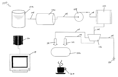
Referring to Figure 1, the basic components of the present beverage brewing
system will now be described.
The beverage brewing systems of the present invention comprise a brewing fluid
reservoir 102. The brewing fluid is preferably water. The reservoir is
designed and
constructed to hold a sufficient amount of brewing fluid for at least one
portion of a
prepared beverage. Preferably, the reservoir will hold a sufficient amount of
brewing fluid
(2-20 portions worth) so as eliminate the inconvenience of repeatedly
refilling the
reservoir after each use of the system.
The beverage brewing system may optionally contain a brewing fluid
purification
device 106. Such devices include filters, chemical purification devices, and
the like. A
system pump 108 is used to draw fluid from the reservoir 102, through supply
line 104, to
the remaining components of the beverage brewing system. Suitable pumping
devices
include, but are not limited to, piston, diaphragm, pressurized head system,
and peristaltic
pumping mechanisms.
The pumping device 10~, pumps fluid through supply line 104 to a fluid heating
device 110. Heater 110 heats the brewing fluid to a sufficient temperature
(preferably
from about 150°F to about 210°F) to enable proper extraction
and/or solubilization of the
ingredients contained in the beverage brewing device.
From heating unit 110, the brewing fluid travels through supply line 104 to a
fluid
directing device 112. The fluid directing device directs water to one or more
fluid
insertion devices 114. The exact number of fluid insertion mechanisms is
dictated by the
22
CA 02440047 2003-09-02
WO 02/074144 PCT/US02/08282
design and functional requirements of the beverage brewing device 122. For
example,
beverage brewing devices with multiple (i.e., more than one) fluid
introduction sites to
enable brew strength control (e.g., via multiple ingredient extraction
chambers and/or
fluid bypass) would require multiple fluid introduction mechanisms.
It is within the scope of the present invention, as will be appreciated by one
of
ordinary skill in the art, that an quantity of fluid introduction mechanisms
may be
provided on the beverage brewing system to accommodate numerous beverage
brewing
devices, and not all would be utilized in each operation of the system.
Control of the fluid
directing device can be accomplished by system controller 116, or
alternatively, and
equally preferable by leavers, knobs, switches, servos, valves and other such
suitable
mechanisms.
Fluid directed to one or more fluid introduction devices 114 enters beverage
brewing device 122. The fluid then passes through the various compartments,
passages,
channels, conduits, components, assemblies, and sub-assemblies of beverage
brewing
device 122 and exits directly into cup 124, ready to be consumed.
System controller 116 controls the various functions of the beverage brewing
system. Such functions i_n.clude, but are not limited to, fluid flow rate,
fluid temperature
control, direction of brewing fluid to one or more fluid introduction
mechanisms, fluid
introduction, and the like. System controller 116 also controls various
feedback control
systems for ensuring appropriate heating profiles, pump operation for
appropriate
brewing fluid flow, and the like.
It will be appreciated by one skilled in the art that system control 116 is
described
as single operating unit solely for the convenience of the reader, and such
description is
not intended to be limiting. In various embodiments of the present invention
it is
contemplated that system controller 116 be comprised of one or more system
controlling
devices including, but not limited to, electrical, mechanical, software, and
the like,
including combinations thereof.
System controller 116 is connected to user interface 160. User interface 160
is
device or set of devices that enable the consumer to select the desired
characteristics of
the finished, ready to drink, brewed beverage product. User interface 160 can
be any form
of suitable device including, but not limited to, knobs, levers, switches,
buttons, dials,
23
CA 02440047 2003-09-02
WO 02/074144 PCT/US02/08282
keys, and the like, including combinations thereof. It alternate embodiments
of the
present invention the user interface is a graphical user interface comprising
user interface
software and corresponding display hardware. It is also contemplated that user
interface
160 can be a combination of electrical, mechanical, software devices, and the
like,
including combinations thereof.
A system user selects one or more desired finished beverage characteristics
(depending on the capabilities of the beverage brewing system and intended
beverage
brewing device) via user interface 160. System controller 116 then controls
the various
components of the beverage brewing system to deliver the brewing fluid
contained in
reservoir 102 to beverage brewing device 122. System controller 116 controls
the various
components of the beverage brewing system to ensure that the brewing fluid
delivered to
the brewing device has the necessary characteristics (temperature profile,
fluid volume,
fluid flow rate, and the like) to allow the beverage brewing device to
generate the desired
beverage.
Optionally. The beverage brewing system may contain a heated fluid supply
device 120, separate and distinct from the fluid insertion mechanism.
(ii) Brewing Fluid Introduction
The fluid introduction mechanisms 114 of the present invention are designed to
insert the brewing fluid from the beverage brewing system 100 to the beverage
brewing
device 122 at one or more fluid introduction sites. In one embodiment of the
present
invention the fluid introduction mechanism 114 is a needle that punctures the
housing of
the beverage brewing device 122 at the fluid introduction site.
In this embodiment the puncturing of the needle occurs as the beverage brewing
device 122 is inserted into the beverage brewing system 100. The fluid
introduction
mechanisms 114 may optionally be fixed to the beverage brewing system 100 such
that
the brewing device 122 is forced into contact with the introduction mechanisms
114 upon
insertion into the system (e.g., needles mounted to the system's housing).
In another embodiment, the fluid introduction mechanism 114 is movable and
comes into contact with the fluid introduction site by a mechanism driven by
the
mechanical force provided by the act of insertion. In such an embodiment, the
fluid
24
CA 02440047 2003-09-02
WO 02/074144 PCT/US02/08282
introduction mechanism 114 comes in contact with the brewing device 122 upon
insertion
into the brewing system 100, and is disconnected from the device 122 upon
removal of
the brewing device from the system.
In another embodiment of the present invention, the fluid introduction
mechanism
114 is a needle. Attached to the needle is a gasket or flange that enables the
formation of
contact seal between the beverage brewing device 122 and the fluid insertion
mechanism
114. Upon removal of the needle from the brewing device 122 the housing of the
device
cleans the needle, aiding in the preservation of brewing system hygiene.
(iii) Beverage Brewing 'Device Recognition System
The beverage brewing systems of the present invention may optionally comprise
one or more beverage brewing device recognition system components. The
beverage
brewing device recognition system allows the beverage brewing system to
recognize the
presence, type and/or capabilities of the beverage brewing device inserted
into the system,
without the need for the consumer to provide such information. For example, a
beverage
brewing device recognition system would recognize the presence of a beverage
brewing
device, thereby inhibiting the activation of a brewing system safety feature
that prohibits
system operation when a beverage brewing device is not present, or is
improperly
inserted. A recognition system may also detect the exact type of beverage
brewing device
inserted (e.g., number of ingredient extraction chambers, orientation, and
required flow
path, and the like), recognize the ingredients contained therein (e.g.,
coffee, tea, creamy
ingredients, combinations thereof, and the like), and identify and initiae the
appropriate
processing conditions required to achieve the desired finished beverage
characteristics.
Recognition of the capabilities of the beverage brewing device could be
accomplished by looking-up the brewing devices capabilities in a remote or
proximately
located database, thereby allowing the database to be updated as new
properties are made
available to the brewing device. Recognition of capabilities could also be
accomplished
by reading such data from the device itself, or the programming, adjustment,
movement,
activation, or deactivation of mechanical switches and/or electrical circuits
on the
beverage brewing system. A combination of such approaches could also be
employed.
CA 02440047 2003-09-02
WO 02/074144 PCT/US02/08282
Suitable methods for recognition of the beverage brewing device include
physical
obstructions, voids, nodules, bumps, ridges, holes, recesses, protrusions, and
the like,
including combinations thereof. These physical recognition system components
are
preferably located on the beverage brewing device housing where, following
insertion of
the brewing device, they can interact with the recognition system components
of the
beverage brewing system (e.g., circuit switches). The combination of
interactions indicate
to the beverage brewing system the type and capabilities of the inserted
beverage brewing
device.
Other suitable recognition system components, for signaling to the beverage
brewing system the type and capabilities of the inserted beverage brewing
device, include
barcodes, magnetic strips, optical recognition, microchips, and the like,
including
combinations thereof. The type and capabilities of the beverage brewing device
can be
encoded into the recognition component of the device and read by a suitable
corresponding component located on the beverage brewing system.
The following examples further describe and demonstrate embodiments within the
scope of the present invention. These examples are given solely for the
purpose of
illustration and are not to be construed as a limitation of the present
invention, as many
variations thereof are possible without departing from the invention's spirit
and scope.
Figures 2- 7 are perspective views of various embodiments of the beverage
brewing system 100 of the present invention. With respect to those figures
brewing
system 100 is provided with a brewing fluid reservoir 102. Reservoir 102 may
be
detachable, or permanently affixed to brewing system 100. System 100 has
housing 140
and beverage container base 142 for receiving and supporting a beverage
container 150
during system operation and beverage preparation. Beverage brewing device 122
is
supported during system operation by a removable brewing device tray 146.
Removable
brewing device tray 146 is in turn mated to and supported by tray support 144,
during
system operation, which is connected to system 100. In use, brewing device 122
is placed
into or onto tray 146, depending on the exact configuration of the brewing
device and the
tray. The tray and device combination is then mated to tray support 144 and
inserted
within housing 140. Insertion may be accomplished by either manual means,
automatic
26
CA 02440047 2003-09-02
WO 02/074144 PCT/US02/08282
means, or combinations thereof. A brewed beverage is then prepared, upon
completion of
which supporting tray 144 is uninserted from housing 140. The combination of
tray 146
and brewing device 122 is then unmated from supporting tray 144. In preferred
embodiments of the present invention tray 146 comprises a handle area 147 by
which the
user may grip tray 146 and conveniently load and unload beverage brewing
devices 122.
Figures 8- 11 are perspective views of various user interface areas 160
located on
housing 140 of beverage brewing system100. Alternatively, the user interface
area may
be remotely or proximately located to brewing system 100, depending on the
exact
configuration and intended operation of system 100. In these embodiments user
interface
area 160 comprises a power activation and status indicator 168 which allows
the user to
activate brewing system 100, and communicates system on/off status to the
user. In
brewing systems capable of beverage customization, user interface area 160
additionally
comprises beverage customization activation and indicator mechanisms 162, 164,
and
166, by which the user may select and receive information concerning the
particular
beverage customization options available. In one embodiment a first, second,
and third
customization activation mechanism is provided corresponding to a mild,
average, or
strong brew strength, respectively. The user, by selecting a particular
customization
activation mechanism, determines the strength of the final beverage that will
be prepared
by system 100 from beverage brewing device 122. Optionally, and preferably,
one or
more customization activation mechanism indicators is provided to allow system
100 to
communicate the particular customization characteristics available to, and
selected by the
user.
Having now described several embodiments of the present invention it should be
clear to those skilled in the art that the forgoing is illustrative only and
not limiting,
having been presented only by way of exemplification. Numerous other
embodiments and
modifications are contemplated as falling within the scope of the present
invention as
defined by the appended claims thereto.
27