Language selection

Search

Patent 2440090 Summary

Third-party information liability

Some of the information on this Web page has been provided by external sources. The Government of Canada is not responsible for the accuracy, reliability or currency of the information supplied by external sources. Users wishing to rely upon this information should consult directly with the source of the information. Content provided by external sources is not subject to official languages, privacy and accessibility requirements.

Claims and Abstract availability

Any discrepancies in the text and image of the Claims and Abstract are due to differing posting times. Text of the Claims and Abstract are posted:

  • At the time the application is open to public inspection;
  • At the time of issue of the patent (grant).
(12) Patent: (11) CA 2440090
(54) English Title: STUD FOR A TYRE
(54) French Title: CLOU POUR PNEU A CLOUS
Status: Deemed expired
Bibliographic Data
(51) International Patent Classification (IPC):
  • B60C 11/16 (2006.01)
(72) Inventors :
  • SALAKARI, HEIKKI (Finland)
(73) Owners :
  • TURVANASTA DEVELOPMENT OY (Not Available)
(71) Applicants :
  • TURVANASTA DEVELOPMENT OY (Finland)
(74) Agent: MARKS & CLERK
(74) Associate agent:
(45) Issued: 2010-06-22
(86) PCT Filing Date: 2002-03-07
(87) Open to Public Inspection: 2002-09-12
Examination requested: 2007-03-06
Availability of licence: Yes
(25) Language of filing: English

Patent Cooperation Treaty (PCT): Yes
(86) PCT Filing Number: PCT/FI2002/000176
(87) International Publication Number: WO2002/070287
(85) National Entry: 2003-09-05

(30) Application Priority Data:
Application No. Country/Territory Date
20010460 Finland 2001-03-08

Abstracts

English Abstract


The invention relates to a stud for a tyre comprising a socket-formed body
portion (1), having at one end a hard metal peak (2) and at its other end a
locking flange (3) retaining the stud in the tyre and being made of a light
injection-mouldable material, such as plastic, the body portion (1) having a
pin (4) extending towards the locking flange, with the tubular sleeve portion
(5) of the locking flange fixed on top of this pin. The body portion (1) is
conical so as to be clamped as a wedge into the corresponding conical sleeve
portion (5).


French Abstract

La présente invention concerne un clou pour pneu à clous. Ce clou est constitué d'un corps en douille (1) dont une extrémité est pourvue d'une pointe en métal dur (2), l'autre extrémité constituant une flasque d'arrêt (3) bloquant le clou dans le pneu et faite d'un matériau léger se moulant par injection, tel que du plastique. Le corps (1) comporte une broche (4) orientée vers la flasque d'arrêt, la partie constituant le manchon tubulaire (5) de la flasque d'arrêt étant fixée au sommet de cette broche. Le corps (1) est conique de façon à être pris en pince comme un coin dans la partie correspondante en manchon conique (5).

Claims

Note: Claims are shown in the official language in which they were submitted.


4

Claims

1. A stud for a tyre comprising a socket-formed body portion (1) having at one
end
a hard metal peak (2) and at the other end a locking flange (3) retaining the
stud in
the tyre, and being made of a light material such as plastic, the body portion
( 1
having a pin (4) extending towards the locking flange, with the tubular sleeve
por-
tion (5) fixed on top of the locking flange, characterised in that the body
portion
(1) is conical over substantially its entire length so as to be clamped as a
wedge into
the corresponding conical sleeve portion (5).

2. A stud as defined in claim 1, characterised in that the conical surface of
the
body portion (1) is graded so that its diameter is larger at the hard metal
peak than
its end (4) at the locking flange (3).

3. A stud as defined in claim 1 or 2, characterised in having a hollow annular
space
(6) at the graded location of the conical surface of the body portion (1) and
the
conical surface of the sleeve portion (5).

4. A stud as defined in any of the preceding claims, characterised in that the
end of
the sleeve portion (5) is open at the locking flange (3).

5. A stud as defined in any of the preceding claims, characterised in having a
con-
cave recess (7) known peg se on the outer surface of the locking flange (3).

6. A stud as defined in any of the preceding claims, characterised in that the
coni-
cal angle relative to the central axis is 3°.

7. A stud as defined in any of the preceding claims, characterised in that the
outer
surface of the sleeve portion (5) is roughened.

Description

Note: Descriptions are shown in the official language in which they were submitted.


CA 02440090 2003-09-05
WO 02/070287 PCT/FI02/00176
1
Stud for a tyre
The invention relates to a stud for a tyre comprising a socket-formed body
portion
having at one end a hard metal peak and at the other end a locking flange
retaining
the stud in the tyre, and being formed of a light material such as plastic,
the body
portion having a pin extending towards the locking flange, with the tubular
sleeve
portion of the locking flange fixed on top of this pin.
As a rule, manufacturers of. winter tyres seek to reduce tyre material, i.e.
rubber
mass, in order to achieve reduced weight of the mass that is without
suspension in
the car and thus enhanced road-holding characteristics. Winter tyres equipped
with
lighter studs also cause less weax to the road surface material. As a result
of the
manufacture of lighter winter tyres, the stud-locking flange gets very close
to the
ply within a winter tyre. There is a distance of only 2-3 mm between the stud-
locking flange and the ply. As a result of this, again, the edge of the stud-
locking
flange has entailed such heavy wear of the tyre rubber under the tilting
movements
of the stud that the internal ply has been damaged and even the tyre
punctured.
There have been constant efforts to provide a stud solution that is durable
while be-
ing as light as possible. Plastic and aluminium studs are known, but they have
poorer resistance than studs with a steel body.
Grravel and asphalt dust cause very rapid wear of the plastic or aluminium
body sur-
rounding the hard metal peak, so that the hard metal peak may easily come off.
Such studs have been disclosed e.g. by FI patent specification 77409 and LTS
patent
specification 3,831,655. The stud described in FI patent specification 77409
is con-
stituted of a metal stud body, around which a collar portion has been
attached, with
the stud flange portion formed at the lower end of the collar portion. This
type of
stud involves the problem of the metal stud body being strongly tapered
towards the
stud flange portion. When the stud is then subjected to pressure in a
direction paral-
lel to the vertical axis of the stud, the metal stud body will act as a wedge
that
causes enlargement of the plastic collar portion. In the course of time, the
plastic
collar portion will be enlarged to an extent such that the metal stud body is
detached
from the collar portion.


CA 02440090 2003-09-05
WO 02/070287 PCT/FI02/00176
2
US patent specification 3,831,655 discloses a stud, in which a shank portion
made
of metal has been connected to the bottom portion made of an elastic material
either
by mechanical joining, gluing or vulcanising. In this stud model, the shank
portion
is clearly narrower than the bottom portion, so that the same apparatus
intended for
mounting conventional studs cannot be used for mounting this stud. The elastic
ma-
terial of the bottom portion of the stud does not extend over the shank
portion at all,
or does so only over a short distance. This results in low friction between
the stud
and the tyre, so that the stud may be detached from the tyre.
The purpose of the invention is to provide a stud of a new type, which is both
resis-
tant and light. The stud of the invention is characterised by the body portion
being
conical, so that it is clamped as a wedge into the corresponding conical
sleeve por-
tion.
The invention provides a very lightweight stud with adequate durability
characteris-
tics. The weight of the stud may be even less than half of the weight of a
steel stud
of equal size. The stud causes less wear to the road surface. The stud is more
silent,
since it has lighter weight. The flexible locking flange is substantially
retained in
position despite the tilting of the stud. Since the actual appearance and
dimensions
of the stud do not differ from those of conventional steel studs, the studs
can be
fixed in the tyres using existing operational equipment. Given the small size
of the
metal body portion, there will be very low waste percentage of raw material if
the
manufacture is carried out using turning. In addition, the plastic part has
proved to
withstand abrasion against rubber better than a steel stud, and consequently
the stud
is better retained in the tyre.
Various embodiments of the invention are defined in the dependent claims of
the set
of claims. The locking flange can receive forces exerted on the hard metal
peak of
the stud, especially when the road surface is molten and the stud peak cannot
bite
into the snow mass or the ice surface.
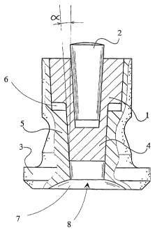
The invention is explained below by means of examples and with reference to
the
accompanying drawing, whose figure shows the stud in partial cross-section.
The stud consists of a socket-formed body portion 1, having a hard metal peak
2 at
one end. At its other end, the body has a locking flange 3 retaining the stud
in the
tyre. The locking flange 3 is made of plastic. The stud body portion 1 has a
pin 4
extending towards the locking pin, the tubular sleeve portion 5 of the locking
flange


CA 02440090 2003-09-05
WO 02/070287 PCT/FI02/00176
3
being fixed on top of this pin. The body portion 1 is conical so as to be
clamped as a
wedge into the corresponding conical sleeve portion 5. The body portion 1 has
a
graded conical surface, its diameter being larger at the hard metal peak 2
than its
end 4 at the locking flange 3. At the graded location of the conical surface
of the
body portion 1 and the conical surface of the sleeve portion 5, there is a
hollow an-
nular space 6, which allows the body portion 1 to be wedged deeper when
pressing
forces are exerted on the stud. The graded feature prevents the body portion
l, if
loosened, from being unintentionally pressed into the tyre of the vehicle and
causing
puncture of this. The end of the sleeve portion 5 is open at the locking
flange so as
to allow the body portion 1 to be wedged into it. The locking flange 3 has a
convex
recess 7 on its outer surface. The conical angle oc relative to the central
axis is 3 °.
The body portion 1 of the stud is not necessarily graded, it may equally well
be an
even cone, however, in that case, the open space 8 requires a collar to
prevent the
body portion from being pressed through the sleeve portion 5 into the tyre of
the
vehicle.

Representative Drawing
A single figure which represents the drawing illustrating the invention.
Administrative Status

For a clearer understanding of the status of the application/patent presented on this page, the site Disclaimer , as well as the definitions for Patent , Administrative Status , Maintenance Fee  and Payment History  should be consulted.

Administrative Status

Title Date
Forecasted Issue Date 2010-06-22
(86) PCT Filing Date 2002-03-07
(87) PCT Publication Date 2002-09-12
(85) National Entry 2003-09-05
Examination Requested 2007-03-06
(45) Issued 2010-06-22
Deemed Expired 2013-03-07

Abandonment History

There is no abandonment history.

Payment History

Fee Type Anniversary Year Due Date Amount Paid Paid Date
Application Fee $150.00 2003-09-05
Maintenance Fee - Application - New Act 2 2004-03-08 $50.00 2003-09-05
Registration of a document - section 124 $100.00 2004-03-31
Maintenance Fee - Application - New Act 3 2005-03-07 $50.00 2005-02-18
Maintenance Fee - Application - New Act 4 2006-03-07 $50.00 2006-02-17
Maintenance Fee - Application - New Act 5 2007-03-07 $100.00 2007-03-05
Request for Examination $400.00 2007-03-06
Maintenance Fee - Application - New Act 6 2008-03-07 $100.00 2008-02-20
Maintenance Fee - Application - New Act 7 2009-03-09 $100.00 2009-02-24
Maintenance Fee - Application - New Act 8 2010-03-08 $100.00 2010-02-18
Final Fee $300.00 2010-04-09
Maintenance Fee - Patent - New Act 9 2011-03-07 $100.00 2011-02-16
Owners on Record

Note: Records showing the ownership history in alphabetical order.

Current Owners on Record
TURVANASTA DEVELOPMENT OY
Past Owners on Record
SALAKARI, HEIKKI
Past Owners that do not appear in the "Owners on Record" listing will appear in other documentation within the application.
Documents

To view selected files, please enter reCAPTCHA code :


To view images, click a link in the Document Description column. To download the documents, select one or more checkboxes in the first column and then click the "Download Selected in PDF format (Zip Archive)" or the "Download Selected as Single PDF" button.

List of published and non-published patent-specific documents on the CPD .

If you have any difficulty accessing content, you can call the Client Service Centre at 1-866-997-1936 or send them an e-mail at CIPO Client Service Centre.


Document
Description 
Date
(yyyy-mm-dd) 
Number of pages   Size of Image (KB) 
Abstract 2003-09-05 2 59
Claims 2003-09-05 1 41
Drawings 2003-09-05 1 16
Description 2003-09-05 3 160
Representative Drawing 2003-09-05 1 12
Cover Page 2003-11-14 1 37
Description 2009-06-19 3 158
Claims 2009-06-19 1 35
Representative Drawing 2010-05-26 1 10
Cover Page 2010-05-26 1 38
PCT 2003-09-05 7 271
Assignment 2003-09-05 2 107
Correspondence 2003-11-12 1 25
Assignment 2004-03-31 2 80
Correspondence 2004-03-31 2 67
Fees 2005-02-18 1 34
Prosecution-Amendment 2007-02-19 1 28
Prosecution-Amendment 2009-01-26 4 141
Prosecution-Amendment 2009-06-19 9 364
Prosecution-Amendment 2007-03-06 1 32
Correspondence 2010-04-09 1 38