Note: Descriptions are shown in the official language in which they were submitted.
CA 02440094 2006-09-28
Attorney Docket No. 1001-116CA
STRUCTURAL REINFORCEMENT MEMBER AND METHOD OF USE THEREFOR
CLAIM OF BENEFIT OF FILING DATE
The present application claims the benefit of the filing date of U.S.
Provisional Application Serial No. 60/409,625, filed September 10, 2002 and
U.S. Application Serial No. 10/646,439, filed August 21, 2003.
FIELD OF THE INVENTION
The present invention relates generally to a structural reinforcement
member and its use in a reinforced structural system.
BACKGROUND OF THE INVENTION
For many years the transportation industry has been concerned with
designing structural reinforcement members that do not add significantly to
the weight of a vehicle. For example, United States Patent Nos. 5,755,486;
4,901,500; and 4,751,249 describe prior art reinforcing devices. The
present invention therefore seeks to provide an improved structural
reinforcement member and a method for its use in a reinforced structural
system.
SUMMARY OF THE INVENTION
The present invention is directed to a structural reinforcement
member adapted for placement in a cavity or elsewhere of an automotive
vehicle for forming a reinforced structural system. Generally speaking, the
assembly may utilize technology and processes such as those disclosed in
U.S. Patent Nos. 4,922,596, 4,978,562, 5,124,186, and 5,884,960 and
commonly owned, co-pending U.S. Application Serial Nos. 09/502,686 filed
February 11, 2000 and 09/524,961 filed March 14, 2000,
The structural reinforcement member
typically includes a carrier member, which employs a first body member
disposed at an angle relative to a second body member. The structural
carrier member also typically employs at least one connector member that
1
CA 02440094 2006-09-28
Attorney Docket No. 1001-116CA
interconnects the first body member with the second body member.
Moreover, the structural reinforcement member typically includes a
reinforcement material disposed on the carrier member. Preferably, the
reinforcement material is an energy absorbing medium, and a heat
activated bonding material. In a particular preferred embodiment, the carrier
member or at least portions thereof could be formed of injection molded
nylon, injection molded polymer, or molded metal (such as aluminum,
magnesium, steel and titanium, an alloy derived from the metals, and even
a metallic foam). The reinforcement material may be a foamable or
expandable material, which could comprise an epoxy-based resin, such as
L5204, L5206, L5207, L5208 or L5209 structural foam commercially
available from L & L Products of Romeo, Michigan. Additional foamable or
expandable materials that could be utilized in the present invention include
other materials which are suitable as bonding mediums and which may be
heat activated foams which activate and expand to fill a desired cavity or
occupy a desired space or function when exposed to temperatures typically
encountered in automotive e-coat and other paint operations. In addition, it
is contemplated that the carrier member could comprise a nylon or other
polymeric material as set forth in commonly owned U.S. Patent No.
6,103,341,
Though other heat-activated materials are possible, a preferred heat
activated material is an expandable or flowable polymeric formulation, and
preferably one that is activated to foam, flow or otherwise change states
when exposed to the heating operation of a typical automotive assembly
painting operation. For example, without limitation, in one embodiment, the
polymeric foam is based on ethylene copolymer or terpolymer that may
possess an alpha-olefin. As a copolymer or terpolymer, the polymer is
composed of two or three different monomers, i.e., small molecules with
high chemical reactivity that are capable of linking up with similar
molecules. Examples of particularly preferred polymers include ethylene
vinyl acetate, EPDM, or a mixture thereof. Without limitation, other examples
of preferred foam formulation that are commercially available include
polymer-based material commercially available from L&L Products, inc. of
2
CA 02440094 2006-09-28
Attorney Docket No. 1001-116CA
Romeo, Michigan, under the designations as L-2105, L-2100, L-7005 or L-
2018, L-7101, L-7102, L-2411, L-2412, L-4141, etc. and may comprise
either open or closed cell polymeric base material.
A number of other suitable materials are known in the art and may
also be used for vibration reduction. One such foam preferably includes a
polymeric base material, such as an ethylene-based polymer which, when
compounded with appropriate ingredients (typically a blowing and curing
agent), expands and cures in a reliable and predicable manner upon the
application of heat or the occurrence of a particular ambient condition. From
a chemical standpoint for a thermally activated material, the vibration
reducing foam is usually initially processed as a flowable thermoplastic
material before curing. It will cross-link upon curing, which makes the
material resistant of further flow or change of final shape.
It is contemplated that the reinforcement material could be delivered
and placed into contact with a member (e.g. a carrier member), through a
variety of delivery systems which include, but are not limited to, a
mechanical snap fit assembly, extrusion techniques commonly known in
the art as well as a mini-applicator technique as in accordance with the
teachings of commonly owned U.S. Patent No. 5,358,397 ("Apparatus For
Extruding Flowable Materials").
In this non-limiting embodiment, the material or medium is at least partially
coated with an active polymer having damping characteristics or other heat
activated polymer, (e.g., a formable hot melt adhesive based polymer or an
expandable structural foam, examples of which include olefinic polymers,
vinyl polymers, thermoplastic rubber-containing polymers, epoxies,
urethanes or the like) wherein the foamable or expandable material can be
snap-fit onto the chosen surface or substrate; placed into beads or pellets
for placement along the chosen substrate or member by means of
extrusion; placed along the substrate through the use of baffle technology; a
die-cast application according to teachings that are well known in the art;
pumpable application systems which could include the use of a baffle and
bladder system; and sprayable applications.
3
CA 02440094 2003-09-09
Attorney Docket No. 1001-116CA
BRIEF DESCRIPTION OF THE DRAWINGS
The features and inventive aspects of the present invention will
become more apparent upon reading the following detailed description,
claims, and drawings, of which the following is a brief description:
Fig. 1 is a perspective view of a structural reinforcement member
according to a preferred aspect of the present invention.
Fig. 2 is a top view of the structural reinforcement member of Fig. 1.
Fig. 3 is a side view of the structural reinforcement member of Fig. 1.
Fig. 4 is a front view of the structural reinforcement member of Fig. 1.
Figs. 5 is a perspective view of the operation of a portion of a
structural reinforcement member according to a preferred aspect of the
present invention.
Fig. 6 is a partially cut away side view of a reinforced structural
system according to a preferred aspect of the present invention.
Fig. 7 is a partially cut away side view of a reinforced structural
system according to another preferred aspect of the present invention.
DETAILED DESCRIPTION OF THE PREFERRED EMBODIMENT
The present invention is predicated upon a structural reinforcement
member and its use in forming a structural reinforcement system within an
article of manufacture. The structural reinforcement member has been
found to be particularly useful for reinforcing portions of automotive
vehicles,
however, it is contemplated that the member may be employed in a variety of
articles of manufacture such as buildings, furniture, watercraft or the like.
Typically, a structural reinforcement member according to the present
invention will include a carrier member with a reinforcement material
disposed thereon. It is also contemplated, however, that the carrier
member may be utilized without the reinforcement material. The carrier
member is generally composed of at least one first body member and at
least one second body member, but preferably, the carrier member includes
a plurality (e.g., 2, 3, 4, 5 or more) of first body members and a plurality
of
second body members. In a preferred configuration, each of the first body
members are disposed at an angle relative to respective second body
4
CA 02440094 2003-09-09
Attorney Docket No. 1001-116CA
members. The carrier member also includes at least one connector
member that interconnects the at least one first body member to the at least
one second body member, but preferably includes a plurality of connector
members each attached to one of the plurality of first body members and
one of the plurality of second body members.
The first body members, the second body members and the
connector members may be provided in a variety of shapes and
configurations. For example, and without limitation, the members may be
cylindrical, rectangular, contoured, angled, bent, curved, planar, non-planar,
flat or the like. The first body members, the second body members and the
connector members may be integrally formed of a singular material or they
may be formed as separate components that are fastened together to form
an integral carrier member. Preferably, the first body members and the
second body members are attached to each other at ends of the first and
second body members while the connector members bridge a space
located substantially between the first and second body members, although
neither is necessarily required. As used herein, the term "bridge" includes
situations where the connector members extends through the space
between the body members, adjacent the space between the body
members or a combination thereof or the like.
Advantageously, according to one preferred embodiment of the
invention, the first body members and the second body members collapse
upon each other in an accordion-like or spring-like manner upon an impact
from a member or entity. At substantially the same time, the connector
members are flexed preferably to fracture as the first body members
collapse upon the second body members. According to this particular
embodiment, the connector members assist in controlling the amount of
energy absorbed and/or transferred by the reinforcement member upon the
occurrence of the impact as will be described further below.
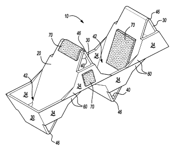
Figs. 1-4 and 6 illustrate an example of a structural reinforcement
member 10, which may be configured for placement within a cavity 12 of an
automotive vehicle (not shown) for forming a reinforced structural system 14
along with one or more components of the vehicle. Preferably, the one or
5
CA 02440094 2003-09-09
Attorney Docket No. 1001-116CA
more components of the vehicle at least partially define the cavity 12. As
will
be appreciated, the member 10 may be suited for placement in a variety of
cavities for reinforcing a variety of components of the automotive vehicle.
The reinforcement member 10 includes a carrier member 20
comprised of a plurality of first body members shown as first body walls 30,
a plurality of second body members shown as second body walls 32 and a
plurality of connector members shown as connector walls 34. The first body
walls 30 and second body wafis 32 are illustrated as substantially
rectangular and each includes a first surface opposite and substantially
parallel to a second surface. The carrier member 20 is preferably elongated
with the first body walls 30 and the second body walls disposed along a
length (L) of the reinforcement member 10. In the depicted embodiment,
the first body walls 30 are disposed intermittently with the second walls 32
along the length (L) of the carrier member 20, however, alterative
configurations may also be utilized.
As shown, each of the first body walls 30 is disposed at an angle 40
with respect to at least one and sometimes a pair of adjoining second body
walls 32 for forming a substantially triangular open space 42 therebetween.
Such a configuration may provide the carrier member 20 and particularly the
body walls 30, 32 in a zig-zag type shape although not required. Preferably,
the body walls 30, 32 are attached to each other at integrally formed
attachment portions 46, which are shown as arcuate portions, which attach
ends of the first and second body walls 30, 32 together. It is contemplated
that the angles 40 at which the walls 30, 32 are disposed relative to each
other may be substantially equivalent to each other or may be different.
The connector walls 34, in the preferred embodiment depicted, are
shaped as truncated triangles with flanges 60 extending outwardly, but may
be formed otherwise as needed or desired. The connector walls 34 are
illustrated as being attached to at least one first body wall 30 and at least
one second body wall 32 adjoining that first body wall 30 thereby bridging
the open space 42 between the first body wall 32 and the second body wall
32. In the preferred embodiment illustrated, each first body wall 30 is
connected to at least one, but possibly two, second body walls 32 by a pair
6
CA 02440094 2003-09-09
Attorney Docket No. 1001-116CA
of connector walls 34 and the connector walls 34 interconnect the sides of
the body walls 30, 32. Also, in the preferred embodiment, the connector
walls 34 may be contoured to, as shown, include or form an arc or angle 66
as shown best in Figs. 4 and 5.
The first and second body walls 30, 32 and the connector walls 34 of
the carrier member 20 are illustrated as being formed of a singular material,
which may be chosen from a variety of materials such as plastics, polymers,
metals, fiberglass or other such materials. In a preferred embodiment, the
members 30, 32, 34 are integrally formed of a molded glass filled nylon.
In Figs. 1-4 and 6, the reinforcement member 10 is illustrated with a
reinforcement material 70 disposed upon the carrier member 20. The
reinforcement material 70 may be disposed upon any portion of the carrier
member 20 and, for illustrative purposes, the reinforcement material 70 has
been disposed on surfaces of the first and second body walls 30, 32, the
arcuate portions 46, the connector walls 34 or combinations thereof.
Preferably, the reinforcement material is a high compressive
strength heat activated reinforcement material having . foamable
characteristics. The material may be generally dry to the touch or tacky and
can be placed upon the surfaces of the members in any form of desired
pattern, placement, or thickness, but is preferably a substantially uniform
thickness. One exemplary expandable material is L-5204 structural foam
available through L&L Products, Inc. of Romeo, Michigan.
Though other heat activated materials are possible for the
reinforcement material 70, a preferred heat activated material is an
expandable plastic, and preferably one that is foamable. A particularly
preferred material is an epoxy-based structural foam. For example, without
limitation, the structural foam may be an epoxy-based material, including an
ethylene copolymer or terpolymer that may possess an alpha-olefin. As a
copolymer or terpolymer, the polymer is composed of two or three different
monomers, i.e., small molecules with high chemical reactivity that are
capable of linking up with similar molecules.
A number of epoxy-based structural reinforcing foams are known in
the art and may also be used to produce the structural foam. A typical
7
CA 02440094 2006-09-28
Attorney Docket No. 1001-116CA
structural foam includes a polymeric base material, such as an epoxy resin
or ethylene-based polymer which, when compounded with appropriate
ingredients (typically a blowing and curing agent), expands and cures in a
reliable and predicable manner upon the application of heat or the
occurrence of a particular ambient condition. From a chemical standpoint
for a thermally-activated material, the structural foam is usually initially
processed as a flowable thermoplastic material before curing. It will cross-
link upon curing, which makes the material incapable of further flow.
An example of a preferred structural foam formulation is an epoxy-
based material that is commercially available from L&L Products of Romeo,
Michigan, under the designations L5206, L5207, L5208, L5209, XP321 and
XP721. One advantage of the preferred structural foam materials over prior
art materials is that the preferred materials can be processed in several
ways. The preferred materials can be processed by injection molding,
extrusion compression molding or with a mini-applicator. This enables the
formation and creation of part designs that exceed the capability of most
prior art materials. In one preferred embodiment, the structural foam (in its
uncured state) generally is dry or relatively free of tack to the touch and
can
easily be attached to the members through fastening means which are well
known in the art.
While the preferred materials for fabricating the reinforcement
material 70 have been disclosed, the reinforcement material 70 can be
formed of other materials provided that the material selected is heat-
activated or otherwise activated by an ambient condition (e.g. moisture,
pressure, time or the like) and cures in a predictable and reliable manner
under appropriate conditions for the selected application. One such
material is the epoxy based resin disclosed in U.S. Patent No. 6,131,897,
filed with the
United States Patent and Trademark Office on March 8, 1999 by the
assignee of this application. Some other possible materials include, but
are not limited to, polyolefin materials, copolymers and terpolymers with at
least one monomer type an alpha-olefin, phenol/formaldehyde materials,
phenoxy materials, and polyurethane materials with high glass transition
8
CA 02440094 2006-09-28
Attorney Docket No. 1001-116CA
temperatures. See also. U.S. Patent Nos. 5,766,719; 5,755,486; 5,575,526;
and 5,932,680. In general, the desired
characteristics of the structural foam include relatively high stiffness, high
strength, high glass transition temperature (typically greater than 70
degrees Celsius), and good corrosion resistance properties. In this
manner, the material does not generally interfere with the materials
systems employed by automobile manufacturers.
In applications where the reinforcement material 70 is a heat
activated, thermally expanding material, an important consideration involved
with the selection and formulation of the material comprising the structural
foam is the temperature at which a material reaction or expansion, and
possibly curing, will take place. For instance, in most applications, it is
undesirable for the material to be reactive at room temperature or otherwise
at the ambient temperature in a production line environment. More typically,
the structural foam becomes reactive at higher processing temperatures,
such as those encountered in an automobile assembly plant, when the
foam is processed along with the automobile components at elevated
temperatures or at higher applied energy levels, e.g., during painting
preparation steps. While temperatures encountered in an automobile
assembly operation may be in the range of about 148.89 C to 204.44 C
(about 300 F to 400 F), body and paint shop applications are commonly
about 93.33 C (about 200 F) or slightly higher. If needed, blowing agent
activators can be incorporated into the composition to cause expansion at
different temperatures outside the above ranges.
Generally, suitable expandable foams have a range of expansion
ranging from approximately 0 to over 1000 percent. The level of expansion
of the structural foam 70 may be increased to as high as 1500 percent or
more. Typically, strength is obtained from products that possess low
expansion.
Some other possible materials include, but are not limited to,
polyolefin materials, copolymers and terpolymers with at least one
monomer type an alpha-olefin, phenol/formaldehyde materials, phenoxy
materials, and polyurethane. See al o U.S. Patent Nos. 5,266,133;
9
CA 02440094 2006-09-28
Attorney Docket No. 1001-116CA
5,766,719; 5,755,486; 5,575,526; 5,932,680; and WO 00/27920 (PCT/US
99/24795), In general,
the desired characteristics of the resulting material include relatively low
glass transition point, and good corrosion resistance properties. In this
manner, the material does not generally interfere with the materials
systems employed by automobile manufacturers. Moreover, it will withstand
the processing conditions typically encountered in the manufacture of a
vehicle, such as the e-coat priming, cleaning and degreasing and other
coating processes, as well as the painting operations encountered in final
vehicle assembly.
In another embodiment, the reinforcement material 60 is provided in
an encapsulated or partially encapsulated form, which may comprise a
pellet, which includes an expandable foamable material, encapsulated or
partially encapsulated in an adhesive shell. An example of one such
system is disclosed in commonly owned, co-pending U.S. Application Serial
No. 09/524,298 ("Expandable Pre-Formed Plug"),
In addition, as discussed previously, preformed patterns may also be
employed such as those made by extruding a sheet (having a flat or
contoured surface) and then die cutting it according to a predetermined
configuration in accordance with the chosen structure, member or surface
and applying it thereto.
The skilled artisan will appreciate that the system may be employed
in combination with or as a component of a conventional sound blocking
baffle, or a vehicle structural reinforcement system, such as is disclosed in
commonly owned co-pending U.S. Application Serial Nos. 09/524,961 or
09/502,686.
During formation of the reinforced structural system 14, the
reinforcing structural member 10 is typically placed within a cavity of an
automotive vehicle for forming the reinforced structural system 14 with one
or more components 80 of the automotive vehicle. As discussed, several
components within an automotive vehicle may form cavities suitable for
receiving a reinforcing structural assembly of the present invention.
CA 02440094 2003-09-09
Attorney Docket No. 1001-116CA
In the exemplary embodiment shown in Figure 6, the member 10 is
placed within a cavity 12 defined by walls 84 of the one or more components
80. As previously discussed, the member 10 may be without reinforcement
material and may act on its own as a reinforcement for the components 80
of the vehicle. Alternatively, however, for embodiments that include the
reinforcement material, the reinforcement material 70 is activated (e.g.,
expanded using heat experienced during an e-coat process or other
painting operation typically encountered in the production of automotive
vehicles), such that the reinforcement material 70, expands, contacts and
adheres to the walls 84 or surfaces of the components 80 adjacent the
materials 70.
Once the reinforcement material 70 is substantially fully expanded
and cured, the reinforcement member 10 reinforces the components 80
and/or other members (e.g., frame members, body members or panels,
pillars or the like) of the vehicle thereby forming reinforced system 14. Upon
sustaining an impact, the reinforcement member 10 provides strength to the
components 80 of the system 14 thereby assisting the system 14 in
resisting the impact.
Advantageously, the reinforcement member 10 provides strength and
resistance to deformation caused by such impacts in a controlled manner.
Particularly, and with additional reference to Fig. 5, an impact that is
experienced at least partially in the direction of elongation of the
structural
reinforcement member 10 causes the first and second body members 30,
32 to move toward each other. As the body member 30, 32 move toward
each other, the connector members 34 are progressively, intermittently or
consecutively fractured. In this manner, the reinforcement member 10 only
substantially provides resistance or strength against an impact up to the
amount of force required to fracture the connector members 34. As
consecutive or intermittent of the connector members 34 fracture, however,
that amount of force is repeatedly applied against the impact. Thus, the
reinforcement member 10 continues to absorb amounts of force or energy
from the impact repeatedly, thereby allowing the reinforcement member 10
provide a less jarring effect due to its impact resistance. Thus, the
11
CA 02440094 2003-09-09
Attorney Docket No. 1001-116GA
reinforcement provides a greater amount of energy dissipation while
transferring a smaller amount of load during an impact.
In the preferred embodiment illustrated particularly in Figs. 4 and 5,
the connector members 34 are arced, angled or bowed out in the preferred
direction of fracture for the connector members 34 thereby offering
additional control to the reinforcement member 10. As shown, the
connector walls 34 are illustrated as fracturing outwardly away from the
sides of the member 10. Alternatively, however, the connector walls may
fracture inwardly, downwardly, upwardly, a combination thereof or the like.
For additional absorption of impact energy, reinforcement material 70
may be located to expand within the open spaces 42 between the body
walls 30, 32. Such reinforcement material 70 may limit or slow movement
of the body walls 30, 32 toward each other upon the occurrence of an
impact. In turn, such reinforcement material assists in absorbing greater
energy from the impact.
In an alternative preferred embodiment, and referring to Fig. 7, the
reinforcement member 10 is placed between a body side inner panel 90
and a body side outer panel 92 of a door or other portion of the vehicle. As
shown the reinforcement member 10 is arranged such that the body walls
30, 32 substantially oppose the body panels 90, 92 of the vehicle while the
connector members 34 extend substantially perpendicular to the panels 90,
92. Preferably, the length (L) of the reinforcement member 10 extends from
one of the panels 90, 92 to the other. It is also preferable for the
reinforcement material 70 to be positioned at the ends of the length (L) of
the reinforcement member 10. It may also be desirable for the
reinforcement material to be positioned only at the ends of the member 10,
although the reinforcement material may be positioned at any of the other
locations discussed herein.
Upon installation, the reinforcement material 70 at the ends of the
length (L) of the reinforcement member 10 may expand and adhere to the
body panels 90, 92 thereby forming a reinforced structural system 94 with
the body panels 90, 92. In operation, the member 10 may be deformed
substantially as previously described.
12
CA 02440094 2003-09-09
Attorney Docket No. 1001-116CA
The preferred embodiment of the present invention has been
disclosed. A person of ordinary skill in the art would realize however, that
certain modifications would come within the teachings of this invention.
Therefore, the following claims should be studied to determine the true
scope and content of the invention.
13