Language selection

Search

Patent 2440182 Summary

Third-party information liability

Some of the information on this Web page has been provided by external sources. The Government of Canada is not responsible for the accuracy, reliability or currency of the information supplied by external sources. Users wishing to rely upon this information should consult directly with the source of the information. Content provided by external sources is not subject to official languages, privacy and accessibility requirements.

Claims and Abstract availability

Any discrepancies in the text and image of the Claims and Abstract are due to differing posting times. Text of the Claims and Abstract are posted:

  • At the time the application is open to public inspection;
  • At the time of issue of the patent (grant).
(12) Patent: (11) CA 2440182
(54) English Title: MAGNET TRACK BRAKING DEVICE
(54) French Title: DISPOSITIF MAGNETIQUE DE FREINAGE SUR RAIL
Status: Deemed expired
Bibliographic Data
(51) International Patent Classification (IPC):
  • B61H 7/08 (2006.01)
(72) Inventors :
  • LEHMANN, HENRY (Germany)
  • KOIDL, HERMANN (Austria)
(73) Owners :
  • KNORR-BREMSE SYSTEME FUER SCHIENENFAHRZEUGE GMBH (Germany)
(71) Applicants :
  • KNORR-BREMSE SYSTEME FUER SCHIENENFAHRZEUGE GMBH (Germany)
(74) Agent: FETHERSTONHAUGH & CO.
(74) Associate agent:
(45) Issued: 2012-05-22
(86) PCT Filing Date: 2002-03-08
(87) Open to Public Inspection: 2002-09-19
Examination requested: 2007-02-02
Availability of licence: N/A
(25) Language of filing: English

Patent Cooperation Treaty (PCT): Yes
(86) PCT Filing Number: PCT/EP2002/002564
(87) International Publication Number: WO2002/072404
(85) National Entry: 2003-09-05

(30) Application Priority Data:
Application No. Country/Territory Date
101 11 685.3 Germany 2001-03-09

Abstracts

English Abstract


The invention relates to a magnet track braking device comprising a magnetic
base
and/or support body and a pole shoe section containing a magnetic flow guiding
area and a
magnetic flow separating area. The invention is characterised in that the
magnetic base and
or support body is made from materials having different magnetic
characteristics, so that an
increase in induction in the gap between the magnet track brake and the rail
head is prevented
when erosion occurs in the pole shoe section.


French Abstract

La présente invention concerne un dispositif magnétique de freinage sur rail (1) comprenant un corps magnétique de base et/ou de support et une partie de pièce polaire comprenant une zone de guidage de flux magnétique et une zone de séparation de flux magnétique. L'invention se caractérise en ce que le corps magnétique de base et/ou de support est constitué de matériaux ayant des caractéristiques de magnétisation différentes, ce qui permet d'éviter une augmentation de l'induction dans l'entrefer entre le frein magnétique sur rail et le champignon de rail (3) lorsque l'usure augmente dans la partie de pièce polaire.

Claims

Note: Claims are shown in the official language in which they were submitted.


1. Magnetic rail braking device with
a magnetic base and/or support body;
a pole shoe region, which pole shoe region has a magnetic flux-guiding region
and a magnetic flux-separating region,
wherein
the magnetic base and/or support body incorporates materials with differing
magnetization characteristic curves so that an increase in induction in the
air gap between
the magnetic rail brake and the rail head is prevented with increasing wear in
the pole
shoe region.

2. Magnetic rail braking device as claimed in claim 1, wherein the magnetic
base
and/or support body has two respective legs and a base body intermediate
region between
the legs.

3. Magnetic rail brake as claimed in one of claims 1 to 2, wherein the two
respective
legs are made from a first magnetic material and the base boy intermediate
region
between the legs is made from a second magnetic material.

4. Magnetic rail braking device as claimed in claim 1, wherein the part of the
pole
shoe region directed towards the rail is made from a friction material.

5. Magnetic rail braking device as claimed in claim 4, wherein the friction
material
is a sintered material.

6. Magnetic rail braking device as claimed in claim 1, wherein the magnetic
flux-
separating region is provided by means of an intermediate strip extending in
the
longitudinal direction of the magnetic rail brake.

7. An electromagnetic rail braking device comprising: a magnetic body for
receiving
a coil of an electromagnet and forming a closed flux path with a rail when the
coil is
activated; a pole shoe section of the magnetic body to be adjacent the rail
head; the
magnetic body including two legs and an intermediate area connecting the legs;
and the
two legs are of a first magnetic material and the intermediate area between
the legs is of a
second magnetic material having different characteristic magnetization curves,
so that a
rise of the induction in the air gap between the electromagnetic rail brake
device and the
rail head is reduced as the wear in the pole shoe section increases.


6


8. The electromagnetic rail braking device according to claim 7, wherein the
part of
the pole shoe section facing the rail comprises a friction material.

9. The electromagnetic rail braking device according to claim 8, wherein the
friction
material is a sintered material.

10. The electromagnetic rail braking device according to claim 7, including an

intermediate strip in a gap of the pole shoe section extending in the
longitudinal direction
of the magnetic rail brake.

11. The electromagnetic rail braking device according to claim 7, including an

intermediate strip between the legs.


7

Description

Note: Descriptions are shown in the official language in which they were submitted.


CA 02440182 2003-09-05

MAGNET TRACK BRAKING DEVICE

The invention relates to an electromagnetic rail braking device having a
magnetic
base body and/or support body, a pole shoe section, the pole shoe section
comprising a
magnetic-flux-guiding area as well as a magnetic-flux-cutting area.

In principle, electromagnetic rail brakes involve an electromagnet consisting
of a coil
extending in the rail direction and horseshoe-like magnetic cores. The direct
current flowing
in the magnetic coil causes a magnetomotive force which generates a magnetic
flux in the
magnetic core, which magnetic flux closes by way of the rail head. The amount
of the
braking force of an electromagnetic rail brake depends on the magnetic
reluctance of the
magnetic circuit, that is, the geometry and permeability, the electric flux,
the coefficient of
friction between the magnetic shoe and the rail as well as the rail condition.

In principle, a differentiation can be made between two different types of
magnets
based on the construction of the brake magnets. In a first embodiment, the
magnetic core
consists of two steel cheeks which are firmly screwed to the coil body on both
sides. As an
alternative, the brake magnet can also be constructed as a link magnet. In the
case of such an
embodiment, the magnetic core is divided into two end pieces and several
connecting links.
The end pieces are firmly screwed to the coil body, and the links can move
freely in the coil
box opening and follow the unevenness of the rail.

Concerning the construction of electromagnetic rail brakes, reference is made
to the
publication "Brakes for Rail Vehicles", Manual of Brake-Related Terms and
Values, Page
45, by Knorr-Bremse AG, Munchen, 1990.

In the case of electromagnetic rail brakes according to the state of the art,
St37 steel is
preferably used for friction materials in the pole shoe section. The use of a
St37 friction layer
has the disadvantage that buildups occur increasingly which considerably
reduce the braking
1


CA 02440182 2003-09-05

force of the brake. In order to restore this braking force, it was necessary
to manually remove
the buildup, which caused high maintenance costs. Although the use of GGG40
cast steel
resulted in less buildup, only low braking forces could be applied by means of
such friction
layers.

A friction material which is distinguished by a low buildup tendency and
permits a
sufficient service life is, for example, a sintered material as a friction
material for the pole
shoe section, the sintered material containing at least one fraction of
pulverized wear inhibitor
and one fraction of a protective-layer-forming powder.

A disadvantage of the use of sintered materials as the friction material was
the
problem that, as the wear of the pole shoes increased, the holding force and
therefore also the
braking forces to be generated increased considerably. These braking forces
rose to twice to
three times the forces in the new condition.

It is therefore an object of the invention to provide an electromagnetic rail
brake, in
the case of which, for example, sintered materials can be used as friction
material for the pole
shoe section for avoiding buildups, where the disadvantages of the prior art
are avoided.
According to the invention, this object is achieved in that the magnetic base
body and/or
support body comprises materials of different characteristic magnetization
curves, so that a
rise of the induction in the air gap between the electromagnetic rail brake
and the rail is
avoided as the wear in the pole shoe section increases. As a result of the
combination of
materials with different characteristic magnetization curves in the magnetic
circuit, it is
achieved that the induction, which increases as a result of the wear of the
pole shoes, drives
the materials in certain areas of the base body farther into the magnetic
saturation and thus
counteracts a rise of the holding force; that is, a rise of the induction in
the air gap between
the electromagnetic rail brake and the rail. In an advantageous embodiment of
the invention,
it can be provided that the magnetic base body and/or support body, in each
case, comprises
two legs and an intermediate area between the legs. In each case, the two legs
comprise a
2


CA 02440182 2011-06-07

first magnetic material, and the intermediate area between the legs comprises
a second magnetic
material. The second magnetic material, which is inserted between the legs, is
a material which
has a characteristic magnetic curve different from that of the base material,
that is, from the
material of the legs, and has the required magnetic characteristics.

The advantage of the present invention is particularly that a constant braking
force is
ensured for the service life of the pole shoes. A higher mechanical stressing
of the
electromagnetic rail brake connected with an increase of the braking forces
can therefore be
prevented.

In accordance with an aspect of the present invention, there is provided an
electromagnetic rail braking device comprising: a magnetic body for receiving
a coil of an
electromagnet and forming a closed flux path with a rail when the coil is
activated; a pole shoe
section of the magnetic body to be adjacent the rail head; the magnetic body
including two legs
and an intermediate area connecting the legs; and the two legs are of a first
magnetic material
and the intermediate area between the legs is of a second magnetic material
having different
characteristic magnetization curves, so that a rise of the induction in the
air gap between the
electromagnetic rail brake device and the rail head is reduced as the wear in
the pole shoe section
increases.

In accordance with another aspect of the present invention, there is provided
a magnetic
rail braking device with a magnetic base and/or support body; a pole shoe
region, which pole
shoe region has a magnetic flux-guiding region and a magnetic flux-separating
region,
characterized in that the magnetic base and/or support body incorporates
materials with differing
magnetization characteristic curves so that an increase in induction in the
air gap between the
magnetic rail brake and the rail head is prevented with increasing wear in the
pole shoe region.

In the following, the invention will be illustrated as an example by means of
the drawing.
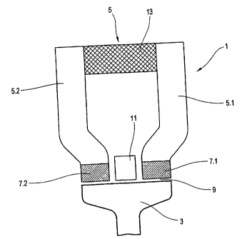
Figure 1 is a schematic view of a rail piece with an electromagnetic brake
with pole
shoes.

3


CA 02440182 2011-06-07

The electromagnetic rail brake 1 illustrated in Figure 1 consists of a coil,
which is not
shown and extends in the longitudinal direction of a rail 3, and of a magnetic
core or base body
or support body 5 whose legs 5.1 and 5.2 extend parallel to one another. Pole
shoes 7.1, 7.2 are
arranged at the end side on the legs 5.1 and 5.2. An air gap 9 is constructed
between the pole
shoes 7.1, 7.2 and the rail head of the rail 3. The pole shoes are preferably
constructed of a
friction material, particularly of a sintered material.

An amagnetic, extremely wear-resistant, shock-resistant and temperature-stable
intermediate strip 11, which fills in the intermediate space, can be arranged
in the intermediate
space between the left and the right pole shoe 7.1, 7.2 (north and south pole
respectively).

3A


CA 02440182 2003-09-05

According to the invention, the magnetic base body and/or support body
comprises
two materials of different characteristic magnetization curves. In the present
case, a first
material is used for the two legs 5.1, 5.2 and a second magnetic material is
used for the base
body intermediate area 13 between the two legs 5.1, 5.2 of the base body. The
second
magnetic material in the base body intermediate area 13 is distinguished by
such a
characteristic magnetization curve that, when, as a result of the wear of the
pole shoes,
because of the shorter path, that is, the decreasing air gap 9, the magnetic
reluctance is
reduced and the induction increases, the second material of the base body
intermediate area
13, which differs from the material of the legs 5.1, 5.2, is driven farther
into the magnetic
saturation, and therefore a rise of the holding force, that is, a rising of
the induction in the air
gap 9 is counteracted.

By means of the present invention, an electromagnetic rail brake is provided
for the
first time which is distinguished by a braking force which remains constant
for the service
life of the pole shoes, so that a higher mechanical stressing of the
electromagnetic rail brake
connected with the increase of the braking forces is reduced.

4

I I,
CA 02440182 2003-09-05

List of Reference Numbers
1 Electromagnetic rail plane

3 rail
base body

5.1, 5.2 leg of the base body
7.1, 7.2 pole shoes

9 air gap

11 intermediate strip

13 base body intermediate area
5

Representative Drawing
A single figure which represents the drawing illustrating the invention.
Administrative Status

For a clearer understanding of the status of the application/patent presented on this page, the site Disclaimer , as well as the definitions for Patent , Administrative Status , Maintenance Fee  and Payment History  should be consulted.

Administrative Status

Title Date
Forecasted Issue Date 2012-05-22
(86) PCT Filing Date 2002-03-08
(87) PCT Publication Date 2002-09-19
(85) National Entry 2003-09-05
Examination Requested 2007-02-02
(45) Issued 2012-05-22
Deemed Expired 2014-03-10

Abandonment History

There is no abandonment history.

Payment History

Fee Type Anniversary Year Due Date Amount Paid Paid Date
Application Fee $300.00 2003-09-05
Registration of a document - section 124 $100.00 2003-11-18
Maintenance Fee - Application - New Act 2 2004-03-08 $100.00 2004-02-24
Maintenance Fee - Application - New Act 3 2005-03-08 $100.00 2005-02-24
Maintenance Fee - Application - New Act 4 2006-03-08 $100.00 2006-02-21
Request for Examination $800.00 2007-02-02
Back Payment of Fees $200.00 2007-02-20
Maintenance Fee - Application - New Act 5 2007-03-08 $200.00 2007-03-06
Maintenance Fee - Application - New Act 6 2008-03-10 $200.00 2008-02-28
Maintenance Fee - Application - New Act 7 2009-03-09 $200.00 2009-02-24
Maintenance Fee - Application - New Act 8 2010-03-08 $200.00 2010-02-24
Maintenance Fee - Application - New Act 9 2011-03-08 $200.00 2011-02-24
Final Fee $300.00 2012-02-16
Maintenance Fee - Application - New Act 10 2012-03-08 $250.00 2012-03-01
Owners on Record

Note: Records showing the ownership history in alphabetical order.

Current Owners on Record
KNORR-BREMSE SYSTEME FUER SCHIENENFAHRZEUGE GMBH
Past Owners on Record
KOIDL, HERMANN
LEHMANN, HENRY
Past Owners that do not appear in the "Owners on Record" listing will appear in other documentation within the application.
Documents

To view selected files, please enter reCAPTCHA code :


To view images, click a link in the Document Description column. To download the documents, select one or more checkboxes in the first column and then click the "Download Selected in PDF format (Zip Archive)" or the "Download Selected as Single PDF" button.

List of published and non-published patent-specific documents on the CPD .

If you have any difficulty accessing content, you can call the Client Service Centre at 1-866-997-1936 or send them an e-mail at CIPO Client Service Centre.


Document
Description 
Date
(yyyy-mm-dd) 
Number of pages   Size of Image (KB) 
Description 2003-09-05 5 184
Drawings 2003-09-05 1 15
Claims 2003-09-05 2 40
Abstract 2003-09-05 1 14
Representative Drawing 2003-11-25 1 10
Cover Page 2003-11-25 1 39
Claims 2010-06-09 2 36
Claims 2009-03-11 2 35
Abstract 2011-09-26 1 14
Description 2011-06-07 6 213
Claims 2011-06-07 2 62
Cover Page 2012-04-25 2 43
Fees 2007-03-06 1 35
PCT 2003-09-05 11 486
Assignment 2003-09-05 2 91
Correspondence 2003-11-20 1 26
PCT 2003-09-06 3 124
Assignment 2003-11-18 2 81
Fees 2005-02-24 1 36
Fees 2004-02-24 1 37
Prosecution-Amendment 2010-07-19 1 16
Correspondence 2010-03-09 1 18
Fees 2010-02-24 1 39
Fees 2006-02-21 1 34
Prosecution-Amendment 2007-02-02 1 45
Prosecution-Amendment 2008-09-11 2 56
Prosecution-Amendment 2009-03-11 4 79
Prosecution-Amendment 2009-08-20 1 28
Prosecution-Amendment 2010-02-22 3 72
Prosecution-Amendment 2010-06-09 6 129
Prosecution-Amendment 2010-12-07 2 57
Fees 2011-02-24 1 36
Prosecution-Amendment 2011-06-07 7 259
Correspondence 2012-02-16 2 62
Fees 2012-03-01 1 65