Note: Descriptions are shown in the official language in which they were submitted.
CA 02440587 2006-12-22
ALL-FIBER BROADBAND POLARIZATION COMBINER
FIELD OF THE INVENTION
This invention relates to an all-fiber polarization combiner for broadband
applications. In
particular, it relates to a Mach-Zehnder (MZ) structure in which the front
coupler which is a
polarization pump combiner (PPC) is made into a broadband combiner by,
controlling the phase
between the two arms of the central zone of the MZ.
BACKGROUND OF THE INVENTION
In applicant's Canadian Patent Application No. 2,354,903 and corresponding
U.S. Patent
Application No. 10/039,571 published under No. US 2003/0031415 Al, there is
disclosed a
polarization combining fused-fiber optical coupler which is operational in a
broad wavelength
bandwidth, i.e. as a broadband coupler. It is made of two polarization
maintaining (PM) fibers
spliced to two standard single mode (SM) fibers which extend and are fused and
drawn to make
a coupling zone. In this arrangement, the linearly polarized light is injected
into the PM fibers
and oriented so that the polarization in one of the PM fibers is orthogonal to
that of the other PM
fiber, and when this light passes through the input arms of the SM fibers (the
axes of which are
aligned with the birefringent axes of the PM fibers) and into the coupling
zone, the two
polarizations are combined in this zone and emerge from one output fiber of
the coupler with
only a minimal power transmission going to the second output fiber.
Furthermore, a polarization selective phase shifting, splitting and combining
optical
device based on a Mach-Zehnder structure is disclosed in applicant's Canadian
Patent
Application No. 2,357,991 and corresponding US Patent Application No.
10/090,128 published
under No. US 2003/0063834 Al. In this MZ structure, a relatively small phase
shift is produced,
typically of one a, by splicing in one of the arms of the central zone a
segment of a PM fiber. A
broadband polarization splitter or combiner may thus be achieved with a Mach-
Zehnder structure
where in the central zone, between the two couplers, a segment of a PM fiber
is spliced in one of
the arms to provide the required phase shifting. This is also described, for
instance, in applicant's
Canadian Patent Application No. 2,357,955 and corresponding U.S. Patent
Application No.
10/045,190 published under No. US 2003/0063833 Al with reference to Fig. 3
embodiment. This
prior patent application also makes reference to broadband WDM fused fiber
couplers.
-1-
CA 02440587 2006-12-22
Another all-fiber depolarizer with a polarization combiner based on a Mach-
Zehnder
interferometer structure is disclosed in applicant's Canadian Patent
Application No. 2,393,172
and corresponding U.S. Patent Application No. 10/397,672 published under No.
US
2004/0008918 Al which also mentions a PPC used in order to scramble pump
polarization.
When it is desired to achieve a broadband operation with the PPC, inverted
WICs (wavelength
independent couplers) are utilized therewith.
SUMMARY OF THE INVENTION
It was surprisingly found that by providing a Mach-Zehnder structure where the
entry
coupler is a PPC and the exit coupler is a wavelength division multiplexer
(WDM) and inducing
the phase shift Ap of n between the two arms in the central zone between the
two couplers, one
obtains a broadband PPC when linearly polarized light is injected into the
input arms of the PPC
coupler from PM fibers spliced to said arms and oriented so that the
polarization X of one PM
fiber is orthogonal to the polarization Y of the other PM fiber. In this
manner, the broadband
effect is maintained throughout the system, leading to the combined
polarizations X and Y
exiting from one of the output arms of the WDM coupler and essentially no
power transmission
going to the second WDM output arm.
Thus, the all-fiber broadband polarization combiner of the present invention
comprises
two polarization maintaining (PM) fibers having input and output ends, and
oriented so that
polarization X in one of the PM fibers is orthogonal to polarization Y in the
other PM fiber, said
PM fibers being spliced by their output ends to the input arms of a
polarization pump coupler
(PPC) which is connected through a central zone to a WDM coupler which has the
same spectral
spacing as the PPC and is centered to the same wavelength, thereby forming a
Mach-Zehnder
(MZ) interferometer structure with the output arm of the WDM coupler forming
the output arms
of the MZ interferometer; the phase shift Ocp between the two arms of the
central zone being set
to a value of n, whereby the PPC is imparted with a broadband polarization
effect and when
broadband power is injected into PM fibers having polarizations X and Y
respectively, it exits in
combined form X and Y from one output arm of the MZ interferometer while the
other MZ arm
essentially has no power transmission going through it. This is due to the
fact that the two
wavelength responses from the two couplers are subtracted from one another.
Thus, by providing a broadband PPC in this manner, use of inverter WICs is
eliminated
-2-
CA 02440587 2006-12-22
and the splicing of a PM fiber section in one of the arms of the central zone
is avoided, thus
removing the necessity to align the coupler arms with the PM fibers at the
entry and reducing
losses due to the splicing of the PM fiber section in the arm of the central
zone. Consequently,
considerable advantages are produced by this simple and efficient MZ
polarization combining
structure.
BRIEF DESCRIPTION OF THE DRAWINGS
A preferred embodiment of the present invention will now be described with
reference to
the appended drawings, in which:
Fig. 1 is a schematic representation of the all-fiber broadband polarization
combiner of
the present invention;
Fig. 2 is a graph showing curves of PPC transmission and WDM coupler
transmission,
where transmission power in dB is plotted with reference to the wavelength in
nm;
Fig. 3 is a graph showing curves of a spectral response of MZ structure of PPC
and WDM
coupler with a zero phase shift plotted in dB power with reference to the
wavelength in nm.
Fig. 4 is a graph showing curves of a spectral response of MZ structure of PPC
and WDM
coupler with a phase shift of n plotted in dB power with reference to the
wavelength in nm; and
Fig. 5 is a graph showing the response at the exit of the broadband
polarization combiner
of the present invention.
DETAILED DESCRIPTION OF THE INVENTION
The invention will now be described by way of a preferred, non-limitative
embodiment,
with reference to the appended drawings.
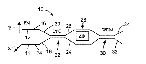
Fig. 1 schematically illustrates the novel all-fiber broadband polarization
combiner 10 in
which two PM fibers 11 and 12 are spliced at points 14 and 16 to standard SM
fibers 18, 20. The
PM fibers 11, 12 may, for example, be PANDATM fibers and the SM fibers are
preferably SMF-
28 fibers of Coming because they are particularly suitable for splicing with
low losses. The PM
fibers 11, 12 are so oriented that when light is injected into them from a
light source (not shown),
it is transmitted with polarizations X and Y being orthogonal to each other.
The light source(s) is
normally broadband, emitting signals with several wavelengths.
The SM fibers 18, 20 form the input arms of PPC 22 which is made by fusing and
-3-
CA 02440587 2006-12-22
elongating these fibers in known manner. The output arms 24 and 26 extend
through a central
zone 28 and are again fused and elongated to form a WDM coupler 30 also in a
known manner.
The WDM coupler has the same spectral spacing as the PPC and is centered to
the same
wavelength. The output arms 32 and 34 of the WDM coupler also represent the
output arms of
the broadband polarization combiner 10.
The structure of the novel broadband polarization combiner 10 is that a Mach-
Zehnder
interferometer (MZ) and the broadband effect is achieved by setting the phase
shift A(p in the
central zone 28 to 7c. It should be noted that the phase shift need not be
precisely 7r which in itself
represents an indefinite number, but merely approximately 7r to achieve the
desired broadband
operation. This phase shift may be imparted by different means, such as
changing the refractive
index of one of the fibers in the central zone 28 by UV radiation or
subjecting one of the fibers to
mechanical stress, or the like. It was surprisingly found that when the a
phase shift is induced
into this MZ structure, the PPC 22 becomes a broadband PPC, thereby making the
entire
polarization combiner 10 a broadband device. As already previously indicated,
the broadband
polarization combiner makes it possible to obtain a wide wavelength bandwidth
greater than 8nm
for an isolation at the outlet of 17 dB or greater.
Fig. 2 shows the transmission curves of PPC and WDM couplers respectively.
Curve A is
the transmission of polarization X and curve B of polarization Y. There were
actually spacings
of 68nm and 75nm for the two orthogonal polarizations. The transmission of the
WDM coupler
is represented by curve C for the two output ports. No broadband polarization
combining is
obtained.
Fig. 3 shows a graph of transmission achieved by the Mach-Zehnder structure
shown in
Fig. 1, but with zero phase shift. Again, curve A is the transmission of
polarization Y, and curve
C is the transmission of the WDM coupler. As is obvious from this graph, the
responses of the
couplers are added to one another in this case, and no broadband polarization
combining is
obtained.
Fig. 4 shows a graph of a transmission achieved by the Mach-Zehnder structure
shown in
Fig. 1 where, in accordance with the present invention, the phase shift is 71.
Curve A is the
transmission of polarization X, curve B is the transmission of polarization Y
and curve C is the
broadband transmission coming of the WDM coupler.
Finally, Fig. 5 shows the power transmission coming out of the two output
ports of the
-4-
CA 02440587 2006-12-22
novel all fiber broadband polarization combiner. Here, it is seen that curves
A and B representing
polarizations X and Y respectively exit from one output port of the device in
a broadband
combination, while at the other output port, the power transmission C is
almost zero.
The invention is not limited to the preferred embodiments described above and
various
modifications obvious to those skilled in the art can be made without
departing from the scope of
the following claims.
-5-