Note: Descriptions are shown in the official language in which they were submitted.
CA 02441052 2003-09-15
PATENT
TEC 1249/C-521
Nelik I. Dreiman
Rick L. Bunch
HORIZONTAL TWO STAGE ROTARY COMPRESSOR
WITH IMPROVED LUBRICATION STRUCTURE
BACKGROUND OF THE INVENTION
[0001] The present invention relates to hermetic compressors and more
particularly to
two stage rotary compressors using carbon dioxide as the working fluid.
[0002] Conventionally, multi-stage compressors are ones in which the
compression of the
refrigerant fluid from a low, suction pressure to a high, discharge pressure
is accomplished in
more than one compression process. The types of refrigerant generally used in
refrigeration
and air conditioning equipment include chlorofluorocarbons (CFCs) and
llydrochlorofluorocarbons (HCFCs). Additionally, carbon dioxide may be used as
the
working fluid in refrigeration and air conditioning systems. By using carbon
dioxide
refrigerant, ozone depletion and global warming are nearly eliminated. Carbon
dioxide is
non-toxic, non-flammable, and has better heat transfer properties than CFCs
and HCFCs, for
example. The cost of carbon dioxide is significantly less than CFC and HCFC.
Additionally,
it is not necessary to recover or recycle carbon dioxide, which contributes to
significant cost
savings in training and equipment.
[0003] In a two-stage compressor, the suction pressure gas is first compressed
to an
intermediate pressure. The intermediate pressure gas is then generally
collected in an
accumulator. From the accumulator, the intermediate pressure gas is drawn into
a second
compressor mechanism where it is compressed to a higher, discharge pressure
for use in the
remainder of the refrigeration system.
[0004] The compression mechanisms of the two-stage compressor may be in one of
two
orientations. The compression mechanisms may be stacked adjacent one another
on one side
of the motor, or positioned with one compression mechanism located on opposite
sides of the
motor. Typically, the compression mechanisms are mounted on the compressor
drive shaft
for rotation therewith. As the drive shaft rotates to drive the compression
mechanisms, an oil
pump mounted at the end of the shaft is actuated. The oil pump is provided to
draw lubricant
from an oil sump in the compressor housing into a longitudinal bore in the
drive shaft and
deliver the lubricant to bearing surfaces in the compressor.
FWIMANI 252613v2 1
CA 02441052 2003-09-15
PATENT
TEC1249/C-521
[0005] The oil pump is generally mounted on the end of the drive shaft. In a
substantially
vertical compressor, the oil pump may be at least partially immersed in the
oil sump. In a
substantially horizontal compressor, the pump is conventionally provided with
an oil pick up
tube extending from the pump into the oil sump. The pump may be a rotary pump
which
includes a fixed casing housing gears, cams, screws, vanes, plungers, or the
like with close
tolerances between the intemal component and the pump casing. The internal
components of
the rotary pump are generally mounted directly on the drive shaft for rotation
therewith. As
the drive shaft rotates, oil is drawn from the oil sump, through the oil pick
up tube, and into
the drive shaft.
[0006] A problem with having the oil pump mounted on the end of the drive
shaft is that
the length of the housing has to be increased to accommodate the pump, thus
increasing the
overall size of the compressor. Further, startup friction is much greater than
operational
friction due to the close tolerances between the internal components and the
pump casing,
which may increase the amount wear on the pump components.
[0007] It is desired to provide a hermetic rotary compressor with an improved
lubrication
system operable upon rotation of the rotor including a piston type pump which
reduces pump
wear and is mounted on the shaft in a position that allows the compressor
housing to be
shortened.
SUMMARY OF THE INVENTION
[00081 The present invention relates to an oil pump for a substantially
horizontal, two-
stage rotary compressor which uses carbon dioxide refrigerant as the working
fluid. The
rotary compressor has a non-rotating or stationary shaft with opposite ends
thereof fixedly
mounted to the compressor housing. A pair of rotary compression mechanisms are
rotatably
disposed about opposite ends of the stationary shaft and are fixed to one
another via an
interference fit between the compression mechanisms and the central bore of
the compressor
motor rotor.
[0009] The stationary shaft is provided with a longitudinal oil passage in
fluid
communication with an oil pump mounted to the stationary shaft. The oil pump
includes a
barrel extending into the oil sump and being integrally formed with a main
body portion.
Located at one end of the main body portion is an ear having a substantially
circular opening
therein in which the stationary shaft is received. A reciprocating piston is
received in the
barrel. Movement of the piston is effected through a ball located between the
piston and a
FWIMAN 1 252613v2 2
CA 02441052 2003-09-15
PATENT
TE01249/C-521
groove formed in the outer surface of an outboard bearing located adjacent the
first stage
compression mechanism. The outer surface of the outboard bearing is eccentric
relative to
the axis of rotation of the motor rotor. The eccentricity imparts cyclical
downward
movement to the piston against the force of a spring located between the lower
end of the
barrel and the end of the piston. The spring is provided to bias the ball into
the outboard
bearing groove.
[0010] Oil is received into the barrel through an inlet port. With the piston
in an upward
position, oil flows through the gap between the coils of the spring into an
axial passage
formed in the piston. The oil is forced into a discharge manifold formed in
the main body
portion as the piston moves downwardly. The oil then flows into the
longitudinal bore in the
stationary shaft to be distributed to the bearing surfaces of the compressor.
A small portion
of the oil is drawn further into the piston to lubricate interfacing surfaces
between the ball and
the outboard bearing.
[0011] The present invention provides a hermetic rotary compressor including a
housing
having an oil sump formed therein. A stationary shaft is fixedly mounted in
the housing with
a longitudinal bore formed in the shaft. A motor is mounted in the housing and
has a rotor
and a stator. The rotor has a first and a second end and is rotatably mounted
on the shaft. A
pair of compression mechanisms is rotatably mounted on the shaft. Each
compression
mechanism is rotatably couple to the rotor and lubricated with oil conducted
through the
longitudinal bore. Each compression mechanism has an outboard bearing
rotatably mounted
on the shaft. An oil pump is mounted on the stationary shaft and is
operatively engaged with
one of the outboard bearings. The oil pump is actuated by rotation of one of
the outboard
bearings and oil is pumped from the sump into the longitudinal bore by the oil
pump.
[0012] The present invention also provides an oil pump for a hernietic rotary
compressor
having a rotatably mounted outboard bearing. The oil pump includes a barrel
having a main
body portion integrally formed therewith. The main body portion has an opening
therein for
mounting the oil pump. A reciprocating piston is received in the barrel and is
operatively
engaged with the outboard bearing such that rotation of the outboard bearing
actuates the oil
pump.
[0013] The present invention provides a method of pumping oil in a hermetic
compressor
to bearing surfaces in the compressor which includes: rotating a compression
mechanism
about a stationary shaft fixed within a compressor housing; moving a
reciprocating piston in
FWIMANI 252613v2 3
CA 02441052 2003-09-15
PATENT
TEC 1249/G521
an oil pump located in the compressor housing in response to rotation of the
compression
mechanism about the stationary shaft; drawing oil from a sump located within
the compressor
housing into the oil pump through movement of the piston; forcing the oil in
the oil pump
into a longitudinal bore formed in the stationary shaft through movement of
the piston; and
distributing oil received from the pump by the longitudinal bore to bearing
surfaces of the
compression mechanism.
[0014] One advantage of the present invention is that the oil pump is moved
from the end
of the stationary shaft to a position closer to the compressor motor allowing
the length of the
compressor housing to be reduced.
[0015] A further advantage of the present invention is that with this type of
oil pump,
startup friction is not much greater than operational friction, which
minimizes that amount of
wear on the pump components.
BRIEF DESCRIPTION OF' THE DRAWINGS
[0016] The above-mentioned and other features and objects of this invention,
and the
manner of attaining them, will become more apparent when the invention itself
will be better
understood by reference to the following description of an embodiment of the
invention taken
in conjunction with the accompanying drawings, wherein:
[0017] Figure 1 is sectional view of a rotary compressor in accordance with
the present
invention;
[0018] Figure 2 is a sectional view of the rotary compressor of Figure 1 along
line 2-2;
100191 Figure 3 is a sectional view of the rotary compressor of Figure 1 along
line 3-3;
[0020] Figure 4 is a sectional view of the rotary compressor of Figure 1 along
line 4-4;
[0021] Figure 5 is a schematic view of the stationary shaft and eccentrics of
the rotary
compressor of Figure 1;
[0022] Figure 6 is an additional sectional view of the rotary compressor in
accordance
with the present invention;
[0023] Figure 7A is a perspective view of the rotary compressor and mounting
assembly
assembled to one another in accordance with the present invention;
[0024] Figure 7B is a perspective view of the mounting assembly of the present
invention;
[0025] Figure 8A is an end view of a mounting assembly for the rotary
compressor of
Figure 1;
FWIMANI 252613v2 4
CA 02441052 2003-09-15
PATENT
TEC 1249/C-521
[0026] Figure 8B is a top plan view of the mounting assembly of Figure 8A;
[0027] Figure 9A is a perspective view of a lug of a pump assembly in
accordance with
the present invention;
[0028] Figure 9B is a front view of the lug of Figure 9A;
100291 Figure 9C is a top view of the lug of Figure 9B;
[0030] Figure 9D is a bottom view of the lug of Figure 913;
[0031] Figure 9E is a sectional view of the lug of Figure 9B taken along line
9E-9E;
[00321 Figure 1 A is a perspective view of a piston of the pump assembly of
the present
invention;
100331 Figure l OB is an elevational view of the piston of Figure 10A;
[00341 Figure l OC is a top view of the piston of Figure l OB; and
[0035] Figure l OD is a sectional view of the piston of Figure l OB taken
along line 10D-
l OD.
[0036] Corresponding reference characters indicate corresponding parts
throughout the
several views. Although the drawings represent an embodiment of the present
invention, the
drawings are not necessarily to scale and certain features may be exaggerated
in order to
better illustrate and explain the present invention.
DETAILED DESCRIPTION OF THE INVENTION
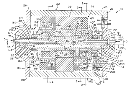
100371 Referring to Figure 1, two-cylinder, two stage rotary horizontal
compressor 20 for
use in a refrigeration system. Compressor 20 includes hermetically sealed
housing 22
defined by main body portion 24 having end caps 26 mounted to each end thereof
by any
suitable method including welding, brazing, or the like. Mounted within
compressor housing
22 is non-rotating, stationary shaft 28 having opposite ends 30 and 32 mounted
in recesses 34
formed in each end cap 26. Located in main body portion 24 of compressor
housing 22 is
electric compressor motor 36 including stator 38 and rotor 40. Stator 38 is,
e.g., interference
or shrink fitted in main body portion 24 to mount motor 36 therein and is
rigidly mounted in
surrounding relationship of rotor 40. Rotor 40 is provided with central
aperture 42 extending
the length thereof in which shaft 28 is received such that rotor 40 is
rotatably disposed about
the stationary shaft.
[0038] Eccentrics 44 and 46 are integrally formed near opposite shaft ends 30
and 32,
respectively, and are engaged by first stage and second stage rotary
compression mechanisms
48 and 50. Eccentrics 44 and 46 are formed on shaft 28 such that one eccentric
44 or 46 is
FWIMANI 252613v2 5
CA 02441052 2003-09-15
PATENT
TEC1249/C-521
located about longitudinal axis 52 of shaft 28 approximately 180 from the
other eccentric 44
or 46 to ensure proper balance of compression niechanisms 48 and 50. Each of
the first and
second stage compression mechanisms 48 and 50 are provided with heads 54 and
56 having
annular flanges 58 and 60, respectively, with substantially cylindrical
projections 62 and 64
extending therefrom. Heads 54 and 56 are mounted on rotor 40 for rotation
therewith with
projections 62 and 64 being secured to rotor 40 by, e.g., press fitting or
shrink fitting such
that flanges 58 and 60 are held tightly against opposite ends of rotor 40.
[0039] Referring to Figures 1 through 4, first and second stage compressing
mechanisms
48 and 50 include cylinder block 66 having inner cylindrical cavity 68 defined
between the
inner surface of inner cylinder block 66 and each of eccentrics 44 and 46. One
roller 70 is
located in each cavity 68 in surrounding relationship of eccentric 44 and 46,
being journaled
thereon. Cylinder block 66 rotates with rotor 40 and roller 70 in the
direction of arrow 67
(Figures 2, 3, and 4) about eccentrics 44 and 46. There is sealing contact
between the roller
eccentric assembly and cavity 68 in cylinder block 66 to provide radial fluid
sealing at the
points where roller 70 engages the inner wall of cylinder block 66. Referring
to Figure 1,
each of the cylinder blocks 66 and rollers 70 has an end surface 71 and 73,
respectively. End
surfaces 71 and 73 of each compression mechanism 48 and 50 are in abutting
contact with
surfaces 72 and 74 of head flanges 58 and 60, respectively. Outboard bearings
78 and 80 are
provided with annular flanges 82 and 84 having surfaces 86 and 88 which are in
abutting
contact with opposite end surfaces 76 and 77 of each cylinder block 66 and
roller 70,
respectively. Apertures are provided in flanges 82 and 84 which align with
oversized
apertures 90 (Figures 2, 3 and 4) provided through cylinder block 66 and
threaded apertures
(not shown) in flanges 58 and 60. Fasteners 92 extend through the aligned
apertures,
threadedly engaging flanges 58 and 60 to interconnect outboard bearings 78 and
80, cylinder
blocks 66, and heads 54 and 56 of respective compression mechanisms 48 and 50.
[0040] Upon assembly of heads 54, 56, cylinder blocks 66, and outboard
bearings 78 and
80, there is an inherent eccentricity between the cylinder block inner
diameter and roller outer
diameter. The eccentricity might cause the interference fit between cylinder
block 66 and
roller 70 to be greater than intended in one portion of the roller orbit and
less than intended in
the opposite portion of the roller orbit. This may induce high internal
stresses in roller 70 and
the connecting compressor components which may lead to premature fatigue
failure. To
address this potential issue and prevent premature failure in the inventive
compressor,
FWIMAN 1 252613v2 6
CA 02441052 2003-09-15
PATENT
TEC1249/C-521
apertures 90 in cylinder block 66 are oversized, allowing the cylinder block
to be located
during compressor assembly so that the preliminary interference fit is
predetermined. In one
example, the interference fit is in the range of 0.0005 to 0.0007 inches,
however, this range
may vary with the size of the compressor.
[0041] Referring to Figure 1, ends 30 and 32 of stationary shaft 28 extend
through
outboard bearings 78 and 80, respectively. Outboard bearings 78 and 80 have
projections 94
and 96 integrally formed therewith, extending from flanges 82 and 84 toward
end caps 26.
Cavity 97 is defined between each projection 94 and 96 and shaft 28 in which
needle bearing
assemblies 98 and 100 are located, being press-fit therein. Bearing assemblies
98 and 100
include a plurality of respective needle bearing elements 103 which rotate on
the outer
surface of shaft 28. The centerline axis of bearing assemblies 98 and 100 is
concentric with
longitudinal axis 52 while projections 94 and 96 have centerline axes 102a and
102b which
are offset from shaft axis 52 by distance D. This allows projections 94 and 96
to rotate
eccentrically about longitudinal axis 52 of stationary shaft 28.
100421 Referring to Figure 5, eccentric portions of projections 94 and 96 have
balance
adjusting parts 104 and 106 which are positioned on opposite sides of shaft 28
having a 180
phase difference about shaft center axis 52. Balance adjusting part 104 is
positioned on shaft
28 approximately 180 from eccentric 44, and balance adjusting part 106 is
positioned
approximately 180 from eccentric 46. Inertia forces Fl and F2 are
respectively produced at
eccentrics 44 and 46 upon rotation of the cylinder blocks 66 and thus outboard
bearings 78
and 80. The inertia forces create inertia couple MF centrally along the length
of shaft 28 and
about an axis perpendicular to shaft axis 52. Balance adjust parts 104 and 106
produce
inertia forces f~ and f2 upon rotation of cylinder blocks 66 and tlius
outboard bearings 78 and
80, thereby producing inertia couple Mf at the same position on shaft 28 as
MF. Inertia
couple Mf is equivalent to inertia couple MF however, Mf acts in an opposite
direction to that
of MF due to the fact that the direction of forces fI and f2 is opposite to
that of forces Fi and
F2. Therefore, the inertia couple MF is counterbalanced by inertia couple Mf
and the shaft
assembly is balanced as a whole. Additionally, counterweights (not shown) may
be provided
adjacent to opposite surfaces 108 and 110 of the corresponding outboard
bearings 78 and 80
to further aid in balancing of compressor assembly 20.
[0043] Compressor 20 is mounted in a substantially horizontal orientation by
external
FWIMAN I 252613v2 7
CA 02441052 2007-04-20
mounting plate 180 shown in Figures 2-4, 7A, 7B, 8A, and 8B. Mounting plate
180 is
attached to outside wall 181 of compressor 20 by any suitable method
including, e.g.,
projection welding which reduces the amount of time required for compressor
assembly.
Referring to Figures 7A, 7B, 8A, and 8B, external mounting plate 180 is an
integral unit
including base 182 having extension legs 184 extending therefrom. Each
extension leg 184 is
provided with hole 186 for mounting compressor 20 to a flat supporting surface
(not shown)
such as the floor or wall of a building or refrigeration system housing. Base
182 is contoured
to match the curvature of compressor outside wall 181 and is formed having
opening 188
which allows for positioning and handling of mounting plate 180 during
assembly. Opening
188 also reduces the amount of area of compressor housing 22 covered by base
182 allowing
more of outside housing wall 181 to be painted for rust protection purposes.
Base 182
includes a plurality of welding projections 190 which are used to weld
external mounting
plate 180 to compressor outside wall 181. Although base 182 is shown having
six welding
projections 190, additional projections or alternative fastening mechanisms
may be used to
secure mounting plate 180 to compressor housing 22. Holes 192 are provided in
opposite
extension legs 184 which are used for a grounding connection for compressor
20.
Compressor 20 may be mounted on either of a horizontal or vertical grounding
surface using
mounting plate 180. In order for compressor 20 to be mounted on a
substantially vertical
grounding surface, oil pump 124, located near end 30 of shaft 28, is kept at
least partially
immersed in motor and oil sump cavity 160 and oil has to be prevented from
entering motor
rotor stator gap 194.
[0044] During compressor operation, a portion of roller 70 engages the wall of
inner
cylindrical cavity 68 formed in cylinder block 66 with the remainder of the
perimeter of roller
70 being separated from the wall of inner cavity 68 (Figures 2, 3 and 4). Vane
112 is
integrally folmed with roller 70 and extends radially therefrom. Vane 112 is
received in guide
assembly 114 mounted in cylinder block 66 to drive roller 70 and form radial
abutment
between cylinder block 66 and roller 70, thereby driving first and second
compression
mechanisms 48 and 50. Guide assembly 114 includes cylindrical bushing 116
located in
cylindrical recess 118 formed in cylinder block 66 adjacent the wall of inner
cylindrical cavity
68. Bushing 116 is provided with longitudinally extending slot 120 in which
the end of vane
112 is slidably received. Cylindrical bushing 116 can be made from any
suitable material
possessing adequate anti-friction properties. One such material includes
VESPELTM
8
CA 02441052 2003-09-15
PATENT
TEC 1249/C-521
SP-21, which is a rigid resin material available from E.I. DuPont de Nemours
and Company.
By using a material having anti-friction properties, the frictional losses
caused by sliding
movement of vane 112 in slot 120 and circumferential movement of bushing 116
in recess
118 of the cylinder block 66 are reduced. Further, the wear between
interfacing surfaces of
vane 112 and recess 118 as well as the interfacing surfaces between
cylindrical bushing 116
and cylinder block 66 is reduced, thereby improving reliability of compressor
20.
[0045] As rotor 40 rotates under the influence of magnetic forces acting
between stator
38 and rotor 40, cylinder blocks 66 and outboard bearings 78 and 80 rotate
with bearing
assemblies 98 and 100 around shaft axis 52. The engagement of vane 112 with
slot 120 in
bushing 116 causes rollers 70 to rotate about the axis of shaft eccentric
portions 44 and 46 in
sync with the rotation of cylinder blocks 66. Rollers 70 eccentrically revolve
in cylinder
blocks 66 and perform the compressive pumping action of compressor 20. Axial
movement
of the assembly including rotor 40 and compression mechanisms 48 and 50 is
limited at one
end by thrust bearing 122 supported by oil pump 124. The axial movement is
limited at the
opposite end by thrust bearing 126 supported by round wire spring 128. Spring
128 may be,
for example, a WAWO spring from Smalley Steel Ring Company located in Lake
Zurich,
IZlinois, U.S.A.
[0046] A fluid flow path is provided through compressor 20 along which
refrigerant
fluid, acted on by first and second stage compression mechanisms 48 and 50,
travels through
the compressor. Referring to Figure 1, suction inlet 130 is mounted in one end
cap 26 by a
method such as welding, brazing, or the like. Suction pressure refrigerant
enters suction inlet
130 and flows through cavity 132 defined between end 30 of shaft 28 and the
bottom of
recess 34 into longitudinally extending bore 134 formed in shaft 28. As shown
in Figure 2, a
plurality of radial passages 136 extend outwardly from bore 134 and are in
fluid
communication with annular channel 138 formed about the periphery of eccentric
portion 44
of first stage compression mechanism 48. Channel 138 is in constant fluid
communication
with radial channel 140 passing through the wall of roller 70. Channel or
passage 140 is
located on one side of vane 112 and directs the refrigerant to crescent shaped
compression
space 144 defined between cylinder block 66 and roller 70 where the
refrigerant is
compressed to a second, intermediate pressure.
[0047] Referring to Figure 3, the compressed fluid is exhausted from
compression space
144 of first stage compression mechanism 48 through radial passage 170.
Passage 170 is
FWIMANI 252613v2 9
CA 02441052 2003-09-15
PATENT
TEC 1249/C-521
located adjacent to the side of vane 112 opposite to the side of vane 112 on
which passage
140 is formed. Fluid in passage 170 enters recess 146 extending about a
portion of the
periphery of eccentric portion 44. As shown in Figure 6, recess 146 is fluidly
connected by
radial channel 150 to a second longitudinal bore 148 extending through shaft
28. Referring to
Figure 6, the end of bore 148 near end 32 of shaft 28 is provided with plug
152 to prevent the
fluid from exiting bore 148 and to direct flow into radial passage 154. The
intermediate
pressure refrigerant flows through passage 154 into channel 156 formed in end
cap 26 and
out of compressor housing 22 through discharge outlet 158. The discharged
intermediate
pressure fluid enters unit cooler 159, schematically shown in Figure 6. Unit
cooler 159 is
located outside of compressor casing 22 where it is cooled before being
introduced into motor
and oil sump cavity 160 through fitting 162. The cooled, intezmediate pressure
refrigerant
gas in cavity 160 flows around and cools motor 36. By cooling the intermediate
pressure gas,
heat from the first stage discharge gas is not transferred to the lubricant in
motor and oil sump
cavity 160 and to the suction pressure gas entering first stage compression
mechanism 48 due
to a small temperature difference between the fluids.
[0048] The cooled, intermediate pressure refrigerant gas is introduced into
second stage
compression mechanism 50 through inlet port 164 (Figure 1) formed in flange 84
of outboard
bearing 80. Baffle 166 is provided with an opening (not shown) facing a
direction opposite
to the direction of rotation of rotor 40. Baffle 166 is mounted to outboard
bearing 80 in
alignment with inlet port 164 to protect against direct suction of oil into
second stage
compression mechanism 50. After the cooled, intermediate pressure refrigerant
gas is
compressed in second stage compression mechanism 50 to a higher discharge
pressure, the
dischaxge pressure gas is discharged into radial passage 168 fonned in roller
70 adjacent to
one side of vane 112. The discharge pressure gas then flows through recess 171
extending
about a portion of the periphery of shaft 28 and radial passage 173 into
longitudinally
extending bore 172 formed in shaft 28 extending from compression mechanism 50
to shaft
end 32. Referring to Figure 1, the discharge pressure gas exits compressor 20
and flows into
cavity 174 formed between end 32 of shaft 28 and the bottom of recess 34 in
end cap 26. The
fluid in cavity 174 then flows through discharge port 176 to the remainder of
the refrigeration
system.
[0049] The suction conduits and passages of the fluid flow system of
compressor 20 are
located on one side of shaft 28 and the discharge channels and conduits are
located on the
FWIIVIAN1 252613v2 10
CA 02441052 2003-09-15
PATENT
TEC 1249/C-521
opposite side of the shaft to prevent overheating of the incoming suction
pressure gas. Static
0-ring seals 178 are positioned about each end 30 and 32 of shaft 28, between
the shaft and
end cap recess 34. Seals 178 prevent leakage of the pressurized refrigerant
gas between
suction and discharge pressure cavities 132 and 174 and intermediate pressure
motor and oil
sump cavity 160.
[0050] Compressor 20 is also provided with a lubricating fluid flow path
through which
lubricating oil accumulated in the lower portion of motor and oil sump cavity
160 is directed
to the compressor components. Referring to Figures 1, and 9A through 9E,
located in the
lubrication flow path is positive displacement, reciprocating piston type oil
pump 124
including a pump barrel 198 having a finely machined or polished inner
cylinder surface 200.
Oil pump 124 further includes lug 202 integrally formed on one side of pump
barrel 198.
Lug 202 extends upwardly from sump 160 and has ear 204 formed at the exposed
end
thereof. Circular opening 206 is formed in ear 204 for mounting oil pump 124
onto
stationary shaft 28.
[0051] Piston 208 has a substantially tubular configuration as shown in
Figures 1, and
10A through l OD to be received ir- barrel 198. Piston reciprocates within
barrel 198 to
induce pumping action of pump 124. Piston 208 includes enlarged annular
portions 210, 212,
and 214, each having an outside diameter substantially equal to the inner
diameter of barrel
198 to establish a sealed relationship between reciprocating piston 208 and
cylindrical surface
200 of barrel 198. Piston 208 is provided with axial channel 216 having
semispherical cavity
218 formed in one end thereof and a smaller diameter axial oil passage 220
extending from
the internal end of channel 216. Passage 220 is in fluid communication with
semispherical
cavity 222 formed at the opposite end of piston 208 from cavity 218 such that
cavities 218
and 222 are in fluid communication. Piston 208 is also formed having a pair of
smaller
diameter portions 224 with one smaller diameter portion 224 being located
between each of
pair of enlarged portions 210 and 212, and 212 and 214. A plurality of ports
226 are fonned
in the smaller diameter portions 224 located between enlarged portions 210 and
212 in fluid
communication with axial channel 216. Ports 226 may be forrned by a plurality
of elongated
slots extending substantially parallel to the longitudinal axis of piston 208.
[0052] Referring to Figure 1, reciprocating movement of piston 208 is provided
by the
eccentricity of projection 94 of outboard bearing 78, which rotates about
fixed shaft 28.
Projection 94 acts as a cam, which communicates motion to follower or piston
208 through
FW IMAN I 252613v2 1 1
CA 02441052 2003-09-15
PATENT
TEC 1249/C-521
roller or bal1228 located in semispherical cavity 222. Bal1228 slides on cam
surface 230 in
curved race or groove 232 formed in the outer surface of projection 94 to
reduce the
compressive stress between the ball and cam surface. The advantage of this
method of
creating reciprocating movement of piston 208 is that the amount of initial
friction between
ball 228 and cam surface 230 is only slightly larger than the operating
f.iiction of pump 124.
[0053) Annular compression spring element 234 is interposed between end 236 of
oil
pump barrel 198 and flange structure 238 defined at end 240 of piston 208 to
keep ball 228 in
constant contact with cam surface 230. Fluid end 236 of oil pump barrel 198 is
provided with
input port 242 bored therein. Input port 242 is located below oil surface
level 196 in oil sump
160, in fluid communication with the oil stored therein.
[0054] Discharge manifold 244 is formed in lug 202 of pump barrel 198 and is
in fluid
communication with longitudinally extending bore 246 formed in shaft 28 via
radial passage
247. Radially extending oil passages 248 (Figure 1) extend from longitudinal
channel 246 to
distribute lubrication to the bearings of the compressor. The reciprocating
movement of
piston 208 causes the volume of chamber 250 defined in barrel 198 between its
end 236 and
end 240 of piston 208 to vary, enabling pumping of the lubricating oil. As
piston 208 moves
upwardly toward shaft 28, the sealed relationship between inner cylindrical
surface 200 of
barrel 198 and the outer diameter of enlarged portion 210 creates a vacuum
which draws
lubricant in motor and oil sump cavity 160 througli input port 242 and into
chamber 250. As
piston 208 moves downwardly, away from sha:ft 28, spring element 234 is
compressed and
the gaps between the spring windings are reduced. The compressed spring
element 234 at
least partially blocks input port 242 to restrict backflow of the lubricating
oil located in pump
chamber 250 toward motor and oil sump cavity 160. As spring element 234 is
compressed,
oil is forced out of chamber 250 and flows upwardly through semispherical
cavity 218, axial
passage 216, and the plurality of ports 226 into discharge manifold 244. The
oil in manifold
244 then flows into channel 246 in shaft 28 and through radial oil passages
248 to lubricate
the compressor bearings. After taie down-stroke of piston 208 is complete, the
piston moves
upwardly within pump barrel 198 under the influence of spring 234, reducing
the amour-t of
pressure acting on oil remaining in chamber 250 and allowing additional oil to
be drawr. into
chamber 250 to repeat the lubricating process.
[0055] A portion of the oil in chamber 250 flowing into discharge manifold 244
travels
upwardly into passage 220. Lubricating oil from motor and oil sump cavity 160
is supplied
FWIMANI 252613v2 12
CA 02441052 2003-09-15
PATENT
TEC 1249/C-521
to the surfaces of ball 228 and semispherical cavity 222 through passage 220
to reduce
friction therebetween. As ball 228 rotates, oil from passage 220 is carried on
the outer
surface thereof to lubricate the interfacing surfaces between ball 228 and cam
surface 230.
[0056] Oil pump 124 may be mounted on either end of shaft 28 due to similarity
in
eccentricity of projections 62 and 64. Alternatively, two oil pumps may be
installed in the
compressor for improving lubrication under extremely difficult conditions such
as when, for
example, high viscosity oil is required for lubrication.
[0057] The location of the pumping chamber and oil inlet being below oil level
196 of oil
in motor and oil sump cavity 160 prevents "gas lock" conditions. Such a
condition might
otherwise occur when the piston element cycles normally, but oil cannot be
pumped because
there is gas captured in chamber 250. Piston movement would then merely cause
compression and expansion of the gas within pumping chamber 250, and thus no
oil would be
pumped to the bearing surfaces. Further, by locating oil pump 124 at its shown
location in
the present invention, rather than at the end of the stationary shaft, the
length of housing 22 is
reduced by the amount otherwise used to accommodate the pump and oil pick up
tube.
[0058] In some compressors, lubricating oil tends to drain away from bearing
surfaces
upon shutdown of the compressor. Upon startup of the compressor, there may be
a delay
before oil can be resupplied to the bearings. In order to prevent the
lubrication delay,
compressor 20 is provided with reservoir 252, as shown in Figure 1, defined by
a gap located
between the inner surface of aperture 42 in rotor 40 and the outer surface of
shaft 28.
Reservoir 252 is a hollow cylindrical cavity in which oil is received from oil
supply bore 246
via radially extending passages 254. Oil in reservoir 252 is then supplied to
eccentrics 44 and
46 and rollers 70 for lubrication thereof.
[0059] The total volume of reservoir 252 can be found using the following
equation:
Vo = B t (R2 - r2)
where t is the distance between facing inner planes of the eccentrics 44 and
46 (cm); r is
radius of shaft 28 (cm); and R is radius of the inner wall surface of aperture
42 in rotor 40
defining a portion of reservoir 252 (cm). Reservoir 252 is charged with a
predetermined
amount of lubricant during assembly of compressor 20 which may be
approximately 1/3 Vo.
[0060] A small portion of the initial assembly charge of lubricant in
reservoir 252 will
leak therefrom before startup of compressor 20 through capillary seals, or
seals formed by an
FWIMAN 1 252613v2 13
CA 02441052 2003-09-15
PATENT
TEC 1249/C-521
oil film located between closely toleranced parts. Capillary seals may be
formed between
eccentrics 44 and 46 and rollers 70, rollers 70 and outboard bearings 78 and
80, and rollers 70
and heads 54 and 56. In the present example, the capillary seals may be in a
range of 0.0003
and 0.0007 inches thick. The amount of oil that leaks axially along shaft 28,
past the
capillary seals, when the compressor is at rest can be calculated from the
following equation:
Qo = 2B R h3 )P/(12:o t)
where h is the thickness of the capillary seal (cm); :o is viscosity of the
oil (centipoise); and )P
is the pressure difference across the seal, which is considered to be
substantially 1 psi.
Therefore, by dividing amount of oil charged in reservoir 252 by the ainount
of initial oil
leakage, a length of time can be determine in which the compressor will loose
the entire
initial charge of oil. A rise of the temperature and pressure during
compressor operation
affects the viscosity of the lubricating oil and, thus, the leakage through
the capillary seals.
The leakage can be computed by the following equation:
Q=(2B IZh3 I12:t)[(1-e B)P)/B]
where B is empirical constant equal to approximately 2.2 x 10⁻⁴; : is the
viscosity of the oil at
100 F (centipoise); and )p is a pressure differential across the seal (psi).
The length of time
in which the compressor will loose the initial assembly oil charge can be
determined by
dividing the initial volume of oil in reservoir 252 by the leakage after
startup. Therefore, if
lubrication can be supplied to bearing surfaces upon compressor startup, until
lubricant from
motor and oil sump cavity 160 can be delivered by pump 124 to the bearing
surfaces, then the
initial volume of oil in reservoir 252 satisfies the lubrication needs of the
compressor.
[0061] During operation of compressor 20, sonie of the initial oil charge and
oil supplied
through the passage 254 to reservoir 252 is distributed under centrifugal
force toward rollers
70 and the surfaces of eccentrics 44 and 46 facing reservoir 252. Upon
shutdown of
compressor 20, oil which accumulates on the cylindrical surfaces defining
reservoir 252, oil
captured in passage 254, and any oil remaining in reservoir 252 accumulates at
the bottom of
reservoir 252 to be immediately distributed to bearing surfaces when the
compressor is again
restarted.
[0062] While this invention has been described as having an exeniplary design,
the
present invention may be further modified within the spirit and scope of this
disclosure. This
application is therefore intended to cover any variations, uses, or
adaptations of the invention
FWIMANI 252613v2 14
CA 02441052 2003-09-15
PATENT
TEC 1249/C-521
using its general principles. Further, this application is intended to cover
such departures
from the present disclosure as come within known or customary practice in the
art to which
this invention pertains.
FWIIv1AN I 252613v2 15