Note: Descriptions are shown in the official language in which they were submitted.
CA 02441151 2003-09-05
4
(Detailed Description of the Invention]
[0001]
[Technical Field]
This invention relates to a technique for manufacturing a seat cushion
of a bucket or bench seat installed in a vehicle such as a car, an aircraft, a
ship
and the like and, in particular, relates to a cushion body of such a seat
cushion,
a method for manufacturing the cushion body and an apparatus for
manufacturing the cushion body.
[0002]
[Prior Art and Problems to be solved by the Invention]
A bucket or bench seat installed in a vehicle such as a car, an aircraft,
a ship and the like has a bottom and a backrest. The bottom is provided with a
cushion (hereinafter referred to as a seat cushion), and the backrest is also
provided with a seat cushion. Such a seat may be provided with a reclining
mechanism andlor a mechanism for jumping up the bottom. In addition, the
bottom andlor the backrest may be provided with a protuberant circumference
for securely supporting a user.
[0003]
The seat cushion comprises a surface material (or a cushion cover) and
a cushion body covered with the surface material. The cushion body has a
main part and a side part generally corresponding to a main part and a side
part of the seat cushion.
[0004]
The cushion body comprises a foamed body formed in a shape
generally corresponding to a shape of the cushion body. The foamed body is
soft to give a soft feeling. The cushion body further comprises a reinforcing
material fixed to the foamed body At least one of the main part and the side
part of the cushion body is reinforced with the reinforcing material, and a
deformation of the seat cushion is thereby restrained to support a user
CA 02441151 2003-09-05
securely.
[0005]
The foamed body is made of a foaming (or expandable) resin. In
general, a foaming urethane resin is used as the foaming resin.
[0006]
The foamed body is manufactured using a foaming apparatus
comprising a molding device. The molding device comprises an upper mold
having an inside corresponding to a shape of a back part of the cushion body
and a lower mold having an inside corresponding to a shape of the main part
and the side part of the cushion body. When the molding device is clamped, an
inner space corresponding to an outline of the cushion body is formed inside
the molding device. An undiluted solution of a foaming resin is injected into
the molding device and expands to form in a shape corresponding to the
outline of the cushion body. Thereby, the foamed body is manufactured.
[0007]
An undiluted solution of cold urethane foam is used as the undiluted
solution of the foaming resin to be injected in the molding device. The
undiluted solution of cold urethane foam produces gas. The gas is trapped
inside the undiluted solution while the undiluted solution of cold urethane
foam expands, so that bubbles of the gas are dispersed inside the expanded
cold urethane foam. A part of gas produced by the undiluted solution is not
trapped inside the expanded cold urethane foam and is exhausted through a
vent holes) provided in the upper mold of the molding device until the inner
space of the molding device is completely filled with the expanded cold
urethane foam. Air initially presented inside the molding device is also
exhausted through the vent hole(s). Then, the foamed body can be formed in a
shape precisely corresponding to the inner space defined by the insides of the
upper and lower molds.
[0008]
CA 02441151 2003-09-05
6
The side part and the back part of the cushion body are reinforced by
use of one or more reinforcing materials. A rigid or half-rigid plate is used
as
the reinforcing material. In order to provide a predetermined strength of
reinforcement required for the cushion body, this reinforcing material is
manufactured by densely binding urethane chips using a binder. Such a
reinforcing material is positioned inside the molding device and an undiluted
solution of a foaming resin is then injected in the molding device. While the
undiluted solution expands to form the complete foamed body, the reinforcing
material is fixed to a portion of the foamed body corresponding to the side
part
andlor the back part of the cushion body. (The undiluted solution of a foaming
resin expands and impregnates into the reinforcing material so that a thin
impregnation layer is formed in an overlapped portion of the foamed body and
the reinforcing material. This thin impregnation layer merely serves to fix
the
reinforcing material to the foamed body. A portion outside of the plate-like
rigid or half rigid reinforcing material adjacent to the thin impregnation
layer
gives a predetermined strength of reinforcement required for the cushion body.
The thin impregnation layer does not have any influences on the strength of
reinforcement of the cushion body.)
[0009]
Such a technique has been used as a technique for reinforcing the
cushion body
[0010]
In such a prior art technique, it is disadvantageously difficult to
deform the rigid or half-rigid plate used as the reinforcing material. If a
portion of the cushion body to be reinforced is not precisely formed in a
predetermined shape, the cushion body is not formed in a predetermined
shape corresponding to an outline of the cushion body, and thus, it is
necessary to cut a part of the reinforcing material before covering the
cushion
body with the surface material, and reinforcing the cushion body costs time
CA 02441151 2003-09-05
7
and care.
[0011]
An object of the invention is to provide a cushion body of a seat
cushion that can be easily reinforced in low cost. Another object of the
invention is to provide a method for manufacturing such a cushion body Still
another object of the invention is to provide an apparatus for manufacturing
such a cushion body
[o012]
[means for solving the Problems]
The invention is a cushion body having a main part and a side part
generally corresponding to a main part and a side part of a seat cushion.
[0013]
The cushion body according to the inventson comprises a foamed body
generally corresponding to an outline of the cushion body and, an
air-permeable material fixed to the foamed body
[0014]
..
The foamed body is made of cold urethane foam. The air-permeable
material is fixed to the foamed body by an impregnation layer formed in an
overlapped portion of the foamed body and the air-permeable material. The
impregnation layer reinforces a portion of the cushion body where the
air-permeable material is fixed.
[0015]
The thickness of the impregnation layer is thinner than that of the
air-permeable material. A surface layer of a portion of the cushion body where
the aix-permeable material is fixed is formed of a non-impregnation layer
outside the air-permeable material adjacent to the impregnation layer.
[0016]
In addition, the impregnation layer has a thickness that can at least
provide a predetermined strength of reinforcement for a portion of the cushion
CA 02441151 2003-09-05
8
body where the air-permeable material is fixed.
[0017]
Thus, the surface layer of a portion of the cushion body where the
air-permeable material is fixed is formed of the non-impregnation layer
outside the air-permeable material adjacent to the impregnation layer, and a
portion of the cushion body where the air-permeable material is fixed is
reinforced.
[0018]
Preferably, a plurality of air-permeable materials is fixed to the side
part of the foamed body, so that the side part of the cushion body can be
reinforced.
[0019]
A soft sponge sheet, a woven sheet or a non-woven sheet is used as the
air-permeable material. Preferably, the sponge sheet is used as the
air-permeable material, and slab urethane foam is used as the sponge sheet.
[0020]
The above cushion body of a seat cushion is manufactured using a
foaming apparatus according to the invention.
[0021]
The foaming apparatus according to the invention comprises a
molding device. The molding device comprises an upper mold and a lower
mold. The upper mold has an inside corresponding to a back part of the
cushion body The lower mold has an inside corresponding to a main paxt and
a side part of the cushion body, When the molding device is clamped, an inner
space corresponding to an outline of the cushion body is formed inside the
molding device. The lower mold has means for exhausting. The exhausting
means preferably comprises a valve and a vent hole connected to the exterior
through the valve. Alternatively, the exhausting means comprises a piston
cylinder and a vent hole connected to the piston cylinder. When the piston
CA 02441151 2003-09-05
9
cylinder is operated after the molding device is clamped, the pressure inside
the molding device is reduced. Preferably, a plurality of vent holes is
provided
in a portion of the inside of the lower mold corresponding to the side part of
the cushion body.
[0022)
In the foaming apparatus according to the invention, not only the
lower mold but also the upper mold has such an exhausting means. Preferably,
one or more vent holes are provided in a portion of the inside of the upper
mold corresponding to the back part of the cushion body.
[0023)
The cushion body of the invention is manufactured as follows. The
air-permeable material is positioned inside the molding device such that the
vent hole of the foaming apparatus of the invention is covered with the
air-permeable material. The valve is opened (or the piston cylinder is
operated). The predetermined amount of the undiluted solution of cold
urethane foam is injected in the molding device, and then, the molding device
is clamped. The undiluted solution of cold urethane foam expands. The valve
is closed (or The operation of the piston cylinder is stopped) at the time
elapsed for a predetermined period after the undiluted solution is completely
injected in the molding apparatus. The undiluted solution is still expanding
at
this time, and the complete foamed body is formed and a predetermined
thickness of the impregnation layer is formed and the air-permeable material
is fixed to the foamed body.
[0024)
While the valve is opened (or the piston cylinder is operated), air and
gas inside the molding device is exhausted through the air-permeable
material and the vent hole. The undiluted solution of cold urethane foam
expands, and bubbles are dispersed inside the expanded undiluted solution.
The expanded undiluted solution reaches on the air-permeable material and
CA 02441151 2003-09-05
then impregnates into the air-permeable material. The bubbles of the
expanded undiluted solution are broken while the expanded undiluted
solution impregnates into the air-permeable material. Thus, a high dense and
hard impregnation layer is formed in the air-permeable material.
[0025]
The thickness of the impregnation layer can be controlled adjusting
the time to close the valve (or adjusting the time to stop the operation of
the
piston cyli.nder). If the time to close the valve (or to stop the operation of
the
piston cylinder) is delayed, the thickness of the impregnation layer is
increased.
[0026]
The time to close the valve (or to stop the operation of the piston
cylinder) is selected between the time when the undiluted solution of cold
urethane foam is completely injected in the molding device and the time when
the maximum expansion rate of the undiluted solution of cold urethane foam
is accomplished.
[0027]
[Mode for carrying out the Invention]
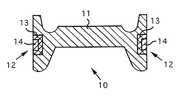
<Cushion Body> As shown in Fig.l, a cushion body 10 of a seat cushion
Gnot shown) according to the invention has a main part and a side part
generally corresponding to a main part and a side part of the seat cushion.
The cushion body 10 comprises a foamed body 11 formed in a shape generally
corresponding to an outline of the cushion body 10, an air-permeable material
12 fixed to the cushion body 10 and an impregnation layer 13 that serves to
reinforce a portion of the cushion body 10 where the air-permeable material
12 is fixed to the foamed body 11. The foamed body 11 is made of cold urethane
foam.
[0028]
The impregnation layer 13 is a layer formed in an overlapped portion
CA 02441151 2003-09-05
11
of the foamed body 11 and the air-permeable material 12. The impregnation
layer 13 serves to fix the air-permeable material 12 to the foamed body 11 and
to reinforce a portion of the cushion body 10 where the air-permeable material
12 is fixed to the foamed body 11.
(0029]
The thickness of the impregnation layer 13 is thinner than that of the
air-permeable material 12, so that a surface layer of a portion of the cushion
body 10 where the air-permeable material 12 is fixed to the foamed body 11 is
formed of a soft non-impregnation layer outside of the air-permeable material
12 adjacent to the impregnation layer 13. The thickness of the impregnation
layer 13 has a thickness that can provide a predetermined strength to
reinforce a portion of the cushion body 10 where the air-permeable material
12 is fixed to the foamed body 11, and thereby, a portion of the cushion body
10
where the air-permeable material 12 is fixed to the foamed body 11 is
reinforced.
(0030]
The air-permeable material as shown can be appropriately fixed to a
portion of the cushion body to be reinforced. A shape and a size of the
air-permeable material can be appropriately selected according to a shape and
a size of a portion of the cushion body to be reinforced. Preferably, a
plurality
of air-permeable materials 12 is fixed to the side part of the foamed body 11,
so
that the side part of the cushion body 10 is reinforced.
(0031]
As mentioned above, the foamed body 11 is made of cold urethane
foam. The cold urethane foam can form a foamed body having a higher impact
resiliency than a foamed body made of hot urethane foam typically used for
manufacturing a cushion body of a seat cushion. In addition, the cure rate of
cold urethane foam is higher than that of hot urethane foam, and thus, a
foamed body can be formed in short time by use of cold urethane foam.
CA 02441151 2003-09-05
12
[0032]
The air-permeable material 12 is selected from a group consisting of a
soft sponge sheet, a woven sheet and a non-woven sheet. Preferably, a sponge
sheet is used as the air-permeable material 12, and slab urethane foam is
used as the sponge sheet.
[0033]
<Manufacturing Apparatus> The cushion body 10 of a seat cushion
according to the invention shown in Fig.l is manufactured using a foaming
apparatus 20 shown in Fig.2. The foaming apparatus 20 comprises a molding
device. The molding device comprises an upper mold 21 and a lower mold 22.
The upper mold 21 has an inside corresponding to a back part of the cushion
body 10. The lower mold 22 has an inside corresponding to the main part and
the side part of the cushion body 10. The lower mold 22 is provided with
means for exhausting. The exhausting means is provided in a portion of the
inside of the lower mold 22 corresponding to the side part of the cushion body
10_ When the molding device is clamped, an inner space 23 corresponding to
an outline of the cushion body 10 is formed inside the molding device. In this
illustrative example, the exhausting means comprises a plurality of vent holes
24, 25 connected to the exterior through valves 29, 29, respectively.
Alternatively, the exhausting means comprises the vent holes 24, 25
connected to piston cylinders (not shown). If the molding device is clamped
and the piston cylinders are operated, the pressure inside the molding device
is reduced.
(0034]
The foaming apparatus 20 is provided with two vent holes 24, 25 in
the lower mold 22, in order to reinforce the side part of the cushion body 10.
Alternatively, as shown in Fig.4, the foaming apparatus 20 may be provided
with two vent holes 27, 28 in the upper mold 21, and two thicker
air-permeable materials 12 are struck into the respective tip portions of
those
CA 02441151 2003-09-05
13
vent holes 27, 28 so as to position those air-permeable materials inside the
molding device. In addition, one or more vent holes connected to the exterior
may be provided at positions selected from the positions of the vent holes
shown in Figs. 2 and 3. Instead of the exhausting means using the valve 29,
the exhausting means using the piston cylinder connected to the vent hole
may be used.
[0035]
<Manufacturing Method> The cushion body 10 shown in Fig. l is
manufactured using the foaming apparatus 20 shown in Fig.2. The cushion
body 10 is manufactured as follows. A plurality of air-permeable materials 12
is positioned inside the molding device such that the vent holes 24, 25
provided in the inside of the molding device are covered with those
air-permeable materials 12, respectively. A predetermined amount of an
undiluted solution of cold urethane foam is injected inside the molding
device,
and the molding device is then clamped. This undiluted solution of cold
urethane foam expands to form the foamed body 11 and a predetermined
..
thickness of the impregnation layer 13 so that those air-permeable materials
13 are fixed to the foamed body 11, respectively The undiluted solution of
cold
urethane foam expands and impregnates into the air-permeable material 13,
and thereby, the impregnation layer 13 is formed.
[0036)
The thickness of the impregnation layer 13 can be controlled adjusting
the diameter of the valve connected to the vent hole of the molding device or
adjusting the time to close the valve after the undiluted solution of cold
urethane foam is completely injected in the molding device. As the valve
diameter increases, the thickness of the impregnation layer 13 increases. The
valve closing time is delayed, the thickness of the impregnation layer 13
increases. As the thickness of the impregnation layer 13 is increased, the
higher strength of reinforcement of the cushion body 10 is given. Thus, the
CA 02441151 2003-09-05
14
strength of reinforcement of the cushion body 10 can be controlled adjusting
the valve diameter and/or adjusting the valve closing time after the undiluted
solution of cold urethane foam is completely injected in the molding device.
(0037]
Preferably, a plurality of air-permeable material 12 is positioned
inside the molding device so as to cover the vent holes provided in the lower
mold 22 of the foaming apparatus 20. Thereby, those air-permeable materials
12 are fixed to portions of the side of the foamed body 11, so that the side
of
the cushion body 10 is reinforced.
[0038]
The air-permeable material 12 is fixed to the foamed body 10 so as to
form the non-impregnation layer 14 in an outer portion of the air-permeable
material 12 that contacts with the vent hole 24, 25 of the upper mold 21.
Thus,
gas produced during the foaming is exhausted through the vent hole 24, 25,
and the expanded undiluted solution does not flow out through the vent hole
24, 25 so that a mushroom-shaped foam formed of the expanded undiluted
solution is not produced in the vent hole 24, 25. This matter is occurred in
the
foaming apparatus 20 shown in Figs.3 and 4.
(0039]
Thickness Control of Impregnation Layer> As mentioned above, the
thickness of the impregnation layer 13 can be controlled adjusting the valve
diameter andl or adjusting the time to close the valve after the undiluted
solution of cold urethane foam is completely injected in the molding device.
[0040]
Gas produced during the foaming is exhausted through the vent hole
and the valve. As the diameter of the valve connected to the vent hole of the
molding device increases, the exhaustion of gas is improved so as to
impregnate the undiluted solution of cold urethane into the air-permeable
material 12 in short time. Meanwhile, as the valve diameter decreases, the
CA 02441151 2003-09-05
exhaustion of gas is restrained so as to impregnate the undiluted solution of
cold urethane into the air-permeable material 12 in long time. Thus, the
thickness control of the impregnation layer 12 can be appropriately done
adjusting the valve diameter.
[0041]
We now consider the time to close the valve after the undiluted
solution of cold urethane foam is completely injected in the molding device.
[0042]
Fig.5 is a graph showing rate of change in expansion and volume. The
rate of change in volume is defined as a volume of the foamed or expanded
undiluted solution of cold urethane foam. In the graph, a curve indicated by
numeral "A" is rate of change in expansion, and a curve indicated by numeral
"B" is rate of change in volume. Numeral "TO" shows time when the foaming is
started, and numeral "T1" is tsme when the maximum rate of change in
expansion is obtained. Numeral "T2" is time when the foaming is terminated.
[0043)
As shown, the undiluted solution of cold urethane foam exhibits a high
fluidity from TO to T1. Between TO and T1, the foaming or expanding pressure
of the undiluted solution of cold urethane foam is high and the impregnation
speed of the undiluted solution of cold urethane foam into the air-permeable
material is high. That is, between TO and T1, form of the impregnation layer
in the air-permeable material is improved.
(0044)
If the valve is continuously opened and time exceeds T1, both the
fluidity of the undiluted solution of cold urethane foam and the impregnation
speed of the undiluted solution axe decreased so that the impregnation layer
incompletely formed in the air-permeable material is pressed to the vent hole
(the vent hole is at lower pressure) by the expanding pressure of the
undiluted
solution of cold urethane foam, and thereby, the impregnation layer is
CA 02441151 2003-09-05
16
deformed. If the valve is continuously opened until. T2, a portion of the
foamed
body around the impregnation layer may be collapsed.
[0045]
Thus, while the thickness of the impregnation layer increases as the
valve closing time is delayed, it is desirable to close the valve between TO
and
T1.
[0046]
<Examples> A cushion body of a seat cushion is manufactured according to
the invention.
[0047]
Cold Urethane Foam: The property of an undiluted solution of cold urethane
foam used is that the expansion is completely terminated in 70 seconds and
the density of foamed body becomes 50 kg/m3.
[0048]
Air-permeable Material: Slab urethane foam is used as an
air-permeable material. Two air-permeable materials are used to cover both
left and right sides of a cushion body The thickness of each air-permeable
material is 30 mm.
(0049]
Foaming Apparatus: A foaming apparatus as shown in Fig.2 is used and
comprises a molding device. The molding device comprises an upper mold and
a lower mold. The lower mold is provided with two vent holes (as indicated
numerals 25 of Fig.2), and each vent hole is connected to the exterior through
a valve. The air-permeable material is positioned inside the molding device
such that the vent hole is covered with the air-permeable material. Examples
1-3 mentioned below are carried out by use of different valve diameters. In
Example 1, the valve diameter of each valve is 1 ~ . In Example 2, the valve
diameter of each valve is 2 ~ . In Example 3, the valve diameter of each valve
is 3 ~ .
CA 02441151 2003-09-05
17
[00501
<Example 1> A cushion body of Example 1 is manufactured as follows. The
valves (each valve diameter i 1 ~) connected to the vent holes of the lower
mold are opened, and each air-permeable material is positioned so as to cover
each vent hole. The undiluted solution of cold urethane foam (1040 g) is
injected, and then, the molding device is clamped. The undiluted solution
expands and impregnates into the air-permeable materials. Then, a foamed
body generally corresponding to an outline of the cushion body is formed, and
the air-permeable materials are fixed to the foamed body so as to reinforce
the
side part of the cushion body The valves are opened fox 25 seconds after the
undiluted solution of cold urethane foam is completely injected in the molding
device, and the valve are then closed. In Example 1, a desired outline of the
cushion body without collapsing is manufactured. The thickness of the
impregnation layer of the cushion body of Example 1 is 4 mm (see Test
Example 1 of Table 1).
[0051)
<Example 2> A cushion body of Example 2 is manufactured as follows. The
valves (each valve diameter is 2 ~ ) connected to the vent holes of the lower
mold are opened, and each air-permeable material is positioned so as to cover
each vent hole. The undiluted solution of cold urethane foam (1040 g) is
injected, and then, the molding device is clamped. The undiluted solution
expands and impregnates into the air-permeable materials. Then, a foamed
body generally corresponding to an outline of the cushion body is formed, and
the air-permeable materials are fixed to the foamed body so as to reinforce
the
side part of the cushion body The valves are opened for 25 seconds after the
undiluted solution of cold urethane foam is completely injected in the molding
device, and the valve are then closed. In Example 2, a desired outline of the
cushion body without collapsing is manufactured as well as Example 1. The
thickness of the impregnation layer of the cushion body of Example 2 is 9 mm
CA 02441151 2003-09-05
18
(see Test Example 2 of Table 1).
[0052]
<Example 3> A cushion body of Example 3 is manufactured as follows. The
valves (each valve diameter is 3 ~ ) connected to the vent holes of the lower
mold are opened, and each air-permeable material is positioned so as to cover
each vent hole. The undiluted solution of cold urethane foam (1040 g) is
injected, and then, the molding device is clamped. The undiluted solution
expands and impregnates into the air-permeable materials. Then, a foamed
body generally corresponding to an outline of the cushion body is formed, and
the air-permeable materials are fixed to the foamed body so as to reinforce
the
side part of the cushion body The valves are opened for 25 seconds after the
undiluted solution of cold urethane foam is completely injected in the molding
device, and the valve are then closed. In Example 3, a desired outline of the
cushion body without collapsing is manufactured as well as Example 1. The
thickness of the impregnation layer of the cushion body of Example 3 is 14
mm (see Test Example 3 of Table 1).
[0053]
<Impregnation Thickness Control Test> The thickness control test of an
impregnation layer to be formed in the air-permeable material is carried out.
[0054]
The test is carried out by use of different valve diameters (1 ~ , 2 ~ and
3 ~) with different valve closing time (25, 30, 35, 40, 45 and 50 seconds).
[0055]
Cold Urethane Foam= The property of an undiluted solution of cold urethane
foam used is that the expansion is completely terminated in 70 seconds and
the density of foamed body becomes 50 kg/m3 (the same as Examples 1-3).
[0056]
Air-permeable Material: Slab urethane foam is used as an
air-permeable material. Two air-permeable materials are used to cover both
CA 02441151 2003-09-05
19
left and right sides of a cushion body. The thickness of each air-permeable
material is 30 mm (the same as Examples 1-3).
[0057]
Foaming Apparatus: A foaming apparatus as shown in Fig.2 is used and
comprises a molding device (the same as Examples 1-3).. The molding device
comprises an upper mold and a lower mold. The lower mold is provided with
two vent holes (as indicated numerals 25 of Fig.2), and each vent hole is
connected to the exterior through a valve. The air-permeable material is
positioned inside the molding device such that the vent holes axe covered with
the air-permeable materials, respectively. Test Examples 1-3 mentioned below
are carried out by use of different valve diameters. In Test Example 1, the
valve diameter of each valve is 1 c~ . In Test Example 2, the valve diameter
of
each valve is 2 ~ . In Test Example 3, the valve diameter of each valve is 3 ~
.
[0058]
<Test Example 1> A cushion body of Test Example 1 is manufactured as
follows. The valves (each valve diameter is 1 ~5 ) connected to the vent holes
of
a
the lower mold are opened, and each air-permeable material is positioned so
as to cover each vent hole. The undiluted solution of cold urethane foam (1040
g) is injected, and then, the molding device is clamped. The undiluted
solution
expands and impregnates into the air-permeable materials. Then, a foamed
body generally corresponding to an outline of the cushion body is formed, and
the air-permeable materials are fixed to the foamed body so as to reinforce
the
side part of the cushion body The valves are opened for 25 seconds after the
undiluted solution of cold urethane foam is completely injected in the molding
device, and the valve are then closed (as same as Example 1). In Test Example
1, the other cushion bodies are also manufactured by opening the valves for
30,
35, 40, 45 and 50 seconds after the undiluted solution of cold urethane foam
is
completely injected in the molding device, and then closing the valves.
[0059]
CA 02441151 2003-09-05
In each of the cushion bodies manufactured by opening the valves for
30, 35, 40 and 45 seconds after the undiluted solution of cold urethane foam,
a
desired outline of the cushion body without collapsing is manufactured. In the
cushion body manufactured by opening the valves for 50 seconds after the
undiluted solution of cold urethane foam, the surface (uon- impregnation
layer) of a portion of the cushion body where the air-permeable material is
fixed swells up, and the cushion body is deformed. The thickness of the
impregnation layer of each of those cushion bodies of Test Example 1 is shown
in Table 1.
[0060]
<Test Example 2> A cushion body of Test Example 2 is manufactured as
follows. The valves (each valve diameter is 2 ~S) connected to the vent holes
of
the lower mold are opened, and each air-permeable material is positioned so
as to cover each vent hole. The undiluted solution of cold urethane foam (1040
g) is injected, and then, the molding device is clamped. The undiluted
solution
expands and, impregnates into the air-permeable materials. Then, a foamed
body generally corresponding to an outline of the cushion body is formed, and
the air-permeable materials are fixed to the foamed body so as to reinforce
the
side part of the cushion body The valves are opened for 25 seconds after the
undiluted solution of cold urethane foam is completely injected in the molding
device, and the valve are then closed (as same as Example 2). In Test Example
2, the other cushion bodies are also manufactured by opening the valves for
30,
35, 40 and 45 seconds after the undiluted solution of cold urethane foam is
completely injected in the molding device, and then closing the valves.
[0061]
In each of the cushion bodies manufactured by opening the valves for
30, 35 and 40 seconds after the undiluted solution of cold urethane foam, a
desired outline of the cushion body without collapsing is manufactured. In the
cushion body manufactured by opening the valves for 45 seconds after the
CA 02441151 2003-09-05
21
undiluted solution of cold urethane foam, the surface (non- impregnation
layer) of a portion of the cushion body where the air-permeable material is
fixed swells up, and the cushion body is deformed. The thickness of the
impregnation layer of each of those cushion bodies of Test Example 2 is shown
in Table 1.
[0062]
<Test Example 3> A cushion body of lbst Example 3 is manufactured as
follows. The valves (each valve diameter is 3 ~) connected to the vent holes
of
the lower mold are opened, and each air-permeable material is positioned so
as to cover each vent hole. The undiluted solution of cold urethane foam (1040
g) is injected, and then, the molding device is clamped. The undiluted
solution
expands and impregnates into the air-permeable materials. Then, a foamed
body generally corresponding to an outline of the cushion body is formed, and
the air-permeable materials are fixed to the foamed body so as to reinforce
the
side part of the cushion body. The valves are opened for 25 seconds after the
undiluted solution of cold urethane foam is completely injected in the molding
device, and the valve are then closed (as same as Example 3). In Test Example
3, the other cushion bodies are also manufactured by opening the valves for
30,
35 and 40 seconds after the undiluted solution of cold urethane foam is
completely injected in the molding device, and then closing the valves.
[0063]
In each of the cushion bodies manufactured by opening the valves for
30 and 35 seconds after the undiluted solution of cold urethane foam, a
desired outline of the cushion body without collapsing is manufactured: In the
cushion body manufactured by opening the valves for 40 seconds after the
undiluted solution of cold urethane foam, the surface (non- impregnation
layer) of a portion of the cushion body where the air-permeable material is
fixed swells up, and the cushion body is deformed. The thickness of the
impregnation layer of each of those cushion bodies of Test Example 3 is shown
CA 02441151 2003-09-05
22
in Table 1.
[0064]
<Results> Results of Test Examples 1-3 are shown in Table 1.
[Table 1]
Table 1
Thickness (mm) of Impregnation Layer
Valve closing Test Example Test Example Test Example
time 1 2 3
25 seconds later4 9 14
30 seconds later7 14 21
35 seconds later10 18 27
40 seconds later12 22 deformed
45 seconds later14 deformed
50 seconds laterdeformed
[0065]
As sown in Table 1, as the valve diameter increases, the thickness of
the impregnation layer increases. As the valve closing time after the
undiluted solution of cold urethane foam is completely injected is delayed,
the
thickness of the impregnation layer is increased. That is, as shown in Table
l,
the thickness of the impregnation layer can be controlled adjusting the valve
diameter and/or adjusting the valve closing time after the undiluted solution
of cold urethane foam is completely injected_ As mentioned, the thickness of
the impregnation layer can be appropriately controlled, and as a result, the
strength of a portion of the cushion body where the air-permeable material is
fixed can be appropriately adjusted.
[0066]
[Effects of the Invention]
The following effects are conducted according to the invention. A
cushion body of the invention can be manufactured by use of a simple method
CA 02441151 2003-09-05
23
comprising the steps of positioning the air-permeable material inside the
molding device having means for exhausting and stopping operation of the
exhausting means at the time elapsed for a predetermined period after the
undiluted solution of cold urethane foam is completely injected in the molding
device. By use of such a simple method, a cushion body of the invention can be
manufactured without generating defects such as a collapse and the like. By
use of such a simple method, a cushion body of the invention can be easily
reinforced in low cost by use of the air-permeable material.
[Brief Description of Drawings]
[Fig. l]
Fig.1 is a cross-sectional view of a cushion body according to the
invention.
[Fig.2]
Fig.2 is a cross-sectional view of a foaming apparatus for
manufacturing the cushion body of Fig.l according to the invention, showing
that a plurality of air-permeable materials is positioned inside the
apparatus.
[Fig.3]
Fig.3 is a cross-sectional view of an alternative example of a foaming
apparatus far manufacturing the cushion body of Fig.l according to the
invention, showing that a plurality of air-permeable materials is positioned
inside the apparatus.
[Fig.4]
Fig.4 is a cross-sectional view of another alternative example of a
foaming apparatus for manufacturing the cushion body of Fig.l according to
the invention, showing that a plurality of air-permeable materials is
positioned inside the apparatus.
[Fig.S]
Fig.5 is a graph showing rate of change in expansion and volume.
[Numerals]
CA 02441151 2003-09-05
24
10... a cushion body
11... a foamed body
12... an air-permeable material
13... an impregnation layer
14... a non-impregnated portion
20... a foaming apparatus
21... an upper mold
22... a lower mold
23... an inner space
24, 25, 26, 27, 28... vent holes
29... a valve