Language selection

Search

Patent 2441311 Summary

Third-party information liability

Some of the information on this Web page has been provided by external sources. The Government of Canada is not responsible for the accuracy, reliability or currency of the information supplied by external sources. Users wishing to rely upon this information should consult directly with the source of the information. Content provided by external sources is not subject to official languages, privacy and accessibility requirements.

Claims and Abstract availability

Any discrepancies in the text and image of the Claims and Abstract are due to differing posting times. Text of the Claims and Abstract are posted:

  • At the time the application is open to public inspection;
  • At the time of issue of the patent (grant).
(12) Patent Application: (11) CA 2441311
(54) English Title: LACE TIGHTENING ARTICLE
(54) French Title: ARTICLE D'ATTACHE DE LACET
Status: Dead
Bibliographic Data
(51) International Patent Classification (IPC):
  • A43C 11/00 (2006.01)
  • A43C 7/00 (2006.01)
  • A43C 9/04 (2006.01)
(72) Inventors :
  • CHRISTY, PHILIP TROY (United States of America)
(73) Owners :
  • CHRISTY, PHILIP TROY (United States of America)
(71) Applicants :
  • CHRISTY, PHILIP TROY (United States of America)
(74) Agent: FETHERSTONHAUGH & CO.
(74) Associate agent:
(45) Issued:
(22) Filed Date: 2003-09-17
(41) Open to Public Inspection: 2005-03-17
Availability of licence: N/A
(25) Language of filing: English

Patent Cooperation Treaty (PCT): No

(30) Application Priority Data: None

Abstracts

English Abstract


An article for tightening together the ends of a lace includes a lace
end receiving device having a pair of flexible, tubular members joined
together
lengthwise, each member including a lengthwise retaining passage therein.
The end of the lace is received within, looped through and held within the
tubular members of the lace end receiving device. By employing two
lace end receiving devices, one at each end of the lace, the devices
may be tied together, whereby the lace is tightened without the lace itself
touching.


Claims

Note: Claims are shown in the official language in which they were submitted.


CLAIMS

What is claimed is:

Claim~ An article for tightening together
opposite end portions of a lace comprising: a first lace end
portion receiving device including; a first elongated tubular
body portion of flexible material , a pair of first elongated,
flexible tubular members forming the first elongated body
portion, each of said first elongated tubular members including
a lengthwise retaining passage therein, the first elongated
tubular members receiving a loop end portion of one end portion
of the lace, said one end portion of said lace extending in
one direction through the passage in one of the first elongated
tubular members and in the opposite direction through the passage
in the other first elongated tubular member, thereby holding
said one end portion of the lace; a second lace end portion
receiving device including; a second elongated tubular body
portion, a pair of second, flexible, tubular members forming
the second elongated body portion, each of the second tubular
members including a lengthwise retaining passage therein, the
second elongated tubular members receiving a looped end portion
of the other end portion of the lace, said other end portion
of the lace extending in one direction through the passage in
one of the second elongated tubular members and in the opposite

5


direction through the passage in the other second elongated
tubular member, thereby holding said other end portion of the
lace, said first and second lace end portions receiving devices
being tied together, whereby the lace is tightened without the
opposite end portions of the lace touching, thereby preventing
fraying of the opposite end portions of the lace.
Claim ~ Thee article according to
claim ~ wherein the first pair and second pair of tubular
members are, respectively, joined together lengthwise.
6


An article for tightening together
opposite end portions of a shoe lace on a shoe comprising: a
first lace end portion receiving device including; a first
elongated tubular body portion of flexible material, a pair
of first elongated, flexible tubular members forming the first
elongated body portion, each of said first elongated tubular
members including a lengthwise retaining passage therein, the
first elongated tubular members receiving a loop end portion
of one end portion of the shoe lace, said one end portion of
said shoe lace extending in one direction through the passage
in one of the first elongated tubular members and in the
opposite direction through the passage in the other first elongated
tubular member, thereby holding said one end portion of the
shoe lace; a second shoe lace end portion receiving device
including; a second elongated tubular body portion, a pair of
second, flexible, tubular members forming the second elongated
body portion, each of the second tubular members including
a lengthwise retaining passage therein, the second elongated
tubular members receiving a looped end portion of the other
end portion of the shoe lace, said other end portion of the
shoe lace extending in one direction through the passage in

7


in one of the second elongated tubular members and in the
opposite direction through the passage in the other second
elongated tubular member, thereby holding said other end
portion of the shoe lace, said first and second shoe lace end
portions receiving devices being tied together, whereby the
shoe lace is tightened without the opposite end portion of
the shoe lace touching, thereby preventing fraying of the
opposite end portions of the shoe lace.
Claim ~ The article according to
claim ~ wherein the first pair and second pair of tubular
members are, respectively, joined together lengthwise.

Description

Note: Descriptions are shown in the official language in which they were submitted.


CA 02441311 2003-09-17
'j .
r,,~,cE ~aGZ-a~.~rrn~G ~xTZe~~
BACGRUU~TD (3P ~k~E I1~JC~1'TIple3
1. Field of the Tnventxon
This invention relates to an artiiele for txghteniug toge~ax the ends
of laces. a not so Iiznited, the article is useful iz~. tightenir~.g ~getJaex
the the ends of shoe laces on ~. shoe.
2. description of the Prior ~lrt
Laces, particula~.y shoe laces, require tying and urtxtying e;actime used,
rnay become unlaced without vvaroi.ng and therefore beeo~me h~:ardous,
and fray and break dus to repetitive tyia$ and Iwotting.
~dditionally~, Iaci~g and unlacing is beyoz~~. t'he ability ox'son7.e osezs,
for example, young children a~ad individuals with cer~n disabilities
such as arthritis.
The prior art bas 'been directed to a solutio~z to or~.e or mare of the
problems posed ,with varying de~cees of success.
Stvxxbbs, U.S. Pat,. No. ??7,63, uses twa cylindrical rnem;bers
placed upon, tie sides of the upper portion of the shoe truough ~vl~ac~a .
the ends of the shoe lace axe passed aztd then taed.
Schelliz~g, U,S. Pst. ~To. 849,921, discloses a fastener for a shoe
string that utilises fkexible ~alar poxtio.
lza. l'Jerrenbergex, U.S. Pat. Rio. 1,172,954, tlxe ends of a lace
axe passed through a. fastener cozaprising hollow, 't~uneated
cone-shaped ferrules.
' Vaiivus Lace fas'te~in~ deices afe showxt in'thE follo~rix~ U.S. ~'atents: '
1


CA 02441311 2003-09-17
r , , .
Price, 2,636 237; ~~dowski, 3,Q74>135; Curry, 5,1.L9,~3~9s
'X'usafan, 5,613,283; atvd, Mua~selt, 3r., 6,192,559 Bl.
Swinton, U.S. Fat. No_ 4,247,967, a~tfiaches hook and pile straps along
the sb~oe Lace.
Gold,1..T.S. Pat. No. 4,564,695, discloses 8 closure ~oaeCl~acx~sm. for a
glotye utilizing a channel member with draw st~ix~g azran~re~rent.
SU~1.Y.1~4RY (7F '~IENTTG'1V
Accordingiy, a primary object off' this invention is the ttgbtening together
of the ends of a lace without the laces aett~ally tauchiz~g, '
~nothcr object is splz~yix~g the 'tying of laces for children.
These and otlaex objects ace accmmplisbed in accoz~daz~ce with. the
teachings o~'lhe present inventivzr, one zllustrative enabodi~.erat.
of ~rhich, cozngzises an ~.cle for tigb~tening together the earls of laces.
The article includes a lace end receiving device having a paax of tubular
me~aabexs
joined toge~er lengfih~uise, eachmeanber incla~ing a lea,~hwise ret~ae~it~ng
passage fibexeia. The end o~ a lace is received 't, looped through
and herd v~itbin, tJae tubular members of ~e lace end rece;i ° device.
By ezuploying two lace egad receiving devices, aye at opposite ends
of the lace, t~.e devices naay be tied toget'1~, whereby the laQe is
txgh~tened
rwithout the laces actually fioucb,i3ag. _
BRIEF DESCRIPTION C?F TkIE 171~'P~'LNG
Other objects features cud advantages o~ the invention wig be apparent
fro8a the following detaxl.ed descripti~n and ar,,companyix~tg chawving,
vrhexeix~:
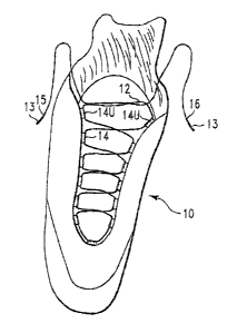
Fig. 1 is a perspective view of a shoe wztb, lace inserted herein;
Fig. 2 is a side view illustrating tl~e sfiep of inserting one end of a lace
2


CA 02441311 2003-09-17
n
in a lace end recesving dev~tce~
Fig. 2A is an e~wlatged, cross sectional vierw taken along t~ze line A--,~, in
Fig. 2;
Fig 2~ is a top view of a lace receivlug device;
Fig. 3 is a fxagmenta~y~, Perspective view illustrating the step vftyialg
together lace end zeceiving deices on the opgosite ends d~f a lace; gad,
Fig. 4 is a perspective view of a shoe illustrating the presn~zt ~.veration
with lace e~td devices tied together fir ~.g'iate~.i~ag the shoe; lace a~~
shoe.
DE'T E~ ESC'T'lt)~T
A shoe,yY is shown ua Fig.I with. a 3.a~ce I2 havir~g tips X3, ailed tlcuough
a series
o~holes or loops 1.4.
T.'he lace 12 is typically of clcatla, lEather or plastic.
A fast 15 and second 16 end o~the shoe lace 12 extend tlotagh the top holes or
Loops
14U.
In Fig., the ~,c~st end 15 of the shoe lace 12 is shown locaped t'hr~ough a
~xzst
lace end receiving device I'~. (erring 2o Figs. 2, 2A axtd , the devzee is
seen as Jlaving s pair o~ tubu~.ar nzez~bers 18,19 ~oiaaed tcegether le wise,
each member izlcluding a laug~.wise passage. 20,21 extending therethxough.
Tile lace '12 is looped tbmugh the device I7 by pushing it up thx~ougla the
first passage 20 and d~wn the sec~z~rl passage 23..
~'he same procedure is fQllo~sred with tile opposite end lei of 'tbe lace 14.
Each device is typically 3 c:~.es lvz~g ~.th passages of 3!8'~ inclx diameter
and made as a single piece ifxoan rare-toxic, ~I~xible plastic. "f~he plastic
is
such as to retazn the Lace within the passages without
slippage and when fled together., to be described hereafter, to .
3


CA 02441311 2003-09-17
footwear, clofihing, packaging and ~oz~t~n.~rs.
It should be obvious that changes, addi~tzo~ and o~ssion:~ nay &~e jade
in the details and arrange~aent of p~xts ~xitbout dep g ~i°o~n tho
spirit
and scope of the invention as hereinafter claimed.
4
Representative Drawing
A single figure which represents the drawing illustrating the invention.
Administrative Status

For a clearer understanding of the status of the application/patent presented on this page, the site Disclaimer , as well as the definitions for Patent , Administrative Status , Maintenance Fee  and Payment History  should be consulted.

Administrative Status

Title Date
Forecasted Issue Date Unavailable
(22) Filed 2003-09-17
(41) Open to Public Inspection 2005-03-17
Dead Application 2006-09-18

Abandonment History

Abandonment Date Reason Reinstatement Date
2005-09-19 FAILURE TO PAY APPLICATION MAINTENANCE FEE

Payment History

Fee Type Anniversary Year Due Date Amount Paid Paid Date
Application Fee $300.00 2003-09-17
Owners on Record

Note: Records showing the ownership history in alphabetical order.

Current Owners on Record
CHRISTY, PHILIP TROY
Past Owners on Record
None
Past Owners that do not appear in the "Owners on Record" listing will appear in other documentation within the application.
Documents

To view selected files, please enter reCAPTCHA code :


To view images, click a link in the Document Description column. To download the documents, select one or more checkboxes in the first column and then click the "Download Selected in PDF format (Zip Archive)" or the "Download Selected as Single PDF" button.

List of published and non-published patent-specific documents on the CPD .

If you have any difficulty accessing content, you can call the Client Service Centre at 1-866-997-1936 or send them an e-mail at CIPO Client Service Centre.


Document
Description 
Date
(yyyy-mm-dd) 
Number of pages   Size of Image (KB) 
Abstract 2003-09-17 1 21
Description 2003-09-17 4 210
Claims 2003-09-17 4 157
Drawings 2003-09-17 2 46
Representative Drawing 2004-01-13 1 7
Cover Page 2005-03-02 1 31
Assignment 2003-09-17 2 89