Note: Descriptions are shown in the official language in which they were submitted.
CA 02441405 2003-09-19
WO 02/076624 PCT/RU02/00108
LIQUID SPRAYERS
Field of the invention
The invention relates to the liquid spraying technique and may be used in fire-
prevention systems, as part of processing equipment, for the burning of fuels
in the heat
engineering and transport, as well as for humidifying the environment and for
spraying
disinfectants and insecticides.
Background of the invention
Diversified types of liquid sprayers are currently used in a variety of
fields, including
the fire-fighting equipment, as fire-extinguishant sprayers.
As an example, the Patent US No 5125582 (IPC BOSB 1/00, published 30.06.1992)
discloses the construction of a liquid sprayer designed for the generation of
cavitation liquid
flows. The prior art comprises a casing with a flow-through channel formed by
a nozzle and a
cylindrical chamber. The nozzle is made in the form of a converging tube
communicated with
a conical diffuser without continuous joining of their surfaces. A length of
the cylindrical
chamber is at least three diameters of a minimal section of the nozzle. On
supplying the liquid
under pressure into the inlet opening of the converging tube of the nozzle,
the liquid flow
section is contracted and the outflow velocity is increased. An abrupt
expansion of the liquid
flow in the diffuser results in liquid cavitation. The liquid cavitation is
intensified in the
process of passage of the liquid jet through the cylindrical chamber, where
the liquid jet is
expanded and return vortex flows are generated. An annular vacuum zone is
formed around a
conical jet to initiate a cavitation process and an associated liquid flow
dispersion process.
However, despite the possibility of an intensified cavitation process, the
prior art liquid
sprayer does not provide for the formation of a steady-state fine-dispersed
liquid flow, that
can retain its shape and section size at the distances of up to 10 m, which is
of particular
importance when the sprayer is employed for suppressing the sources of fire.
A vacuum-type sprayer head (the author's certificate, USSR, No 994022, IPC
BOSB
1/00, published 07.02.1983) is also known, which comprises a nozzle composed
of a
converging tube and a cylindrical head located coaxial with the nozzle. The
cylindrical head is
equipped with ejection holes formed at the side of its outlet opening to admit
atmospheric air
into a vacuum zone in the cylindrical head cavity. As a result the incoming
air saturates the
moving liquid flow to provide for splitting of the flow into small droplets.
CA 02441405 2003-09-19
WO 02/076624 PCT/RU02/00108
2
Russian Patent No 2123871 (IPC A62C 31/02, published 27.12.1998) describes a
head
for forming an aerosol-type water spray, which allows the dispersion of a gas-
drop jet to be
improved. The prior art sprayer (head) comprises a casing having a flow-
through channel
formed as a Laval nozzle, an inlet pipe union for supplying liquid under
pressure, and a
distributing grid located between the pipe union and an inlet section of the
Laval nozzle. The
sizes of the distributing grid holes are 0.3 = 1.0 the diameter of the Laval
nozzle critical
section. While passing through the holes of the distributing grid, the liquid
flow is split into
separate streams, which are sequentially concentrated in the nozzle orifice
and accelerated to
high velocities. Such embodiment provides for a sufficient distance of
discharging a fire
extinguishant and fine spraying.
The closest analog for the claimed versions of the sprayer is a liquid
spraying device
described in the Patent DDR No. 233490 (IPC A62C 1/00, published 05.03.1986),
which is
adapted for feeding a fire-extinguishant to a source of fire. The device is
composed of a
casing involving a flow-through channel, into which a working fluid, including
water, is
supplied under pressure. The flow-through channel of the device is composed of
an inlet
portion formed as a converging tube, a cylindrical portion and an outlet
portion formed as a
conical diffuser, said portions being sequentially joined with one another in
axially aligned
relationship. Also, the device comprises a reservoir containing a fire-
extinguishant, which is
communicated with the diffuser via radial passages.
During operation of said device the liquid (water) is supplied under the
pressure of
1.5 = 2.0 bar into the inlet opening of the flow-through channel and is
sequentially accelerated
in a nozzle formed by the converging tube, the cylindrical portion and the
diffuser. The fire-
extinguishant is ejected into the diffuser through the radial passages to be
further intermixed
with the liquid flow. The implementation of said device allows the reach of
the fire-
extinguishant to be essentially increased to thereby improve the fire-fighting
effectiveness,
when known extinguishants are utilized. However, the given embodiment does not
provide
for the generation of high-velocity fine-dispersed gas-drop jets. The liquid
flow is used in
such devices for the most part as a carrier for an additionally introduced f
re-extinguishant, for
example, for foam-generating additives.
CA 02441405 2003-09-19
WO 02/076624 PCT/RU02/00108
3
Disclosure of the invention
The claimed invention is aimed at generating a steady-state fine-dispersed
liquid spray,
which must retain the shape and size of its section at the distances of up to
10 m, and at
increasing the efficiency of energy consumed for the generation of a gas-drop
jet. Also the
distribution of drop concentration over the section of a fine-dispersed gas-
drop jet must be
homogeneous. The solution of the aforesaid objectives is of particular
importance in the
implementation of liquid sprayers for suppressing the sources of fire.
The technical result which may be achieved through the solution of the tasks
set forth
consists in increasing the fire-fighting effectiveness, when water containing
fire-extinguishing
additives is used, in increasing the effective utilization of a working fluid
and in reducing the
energy consumption for generating a gas-drop jet.
The aforesaid objectives are achieved by providing a liquid sprayer according
to the
first embodiment of the invention comprising a casing having a flow-through
channel
composed of an inlet portion formed as a converging tube, a cylindrical
portion and an outlet
portion formed as a conical diffuser, with said portions being sequentially
joined with one
another in axially aligned relationship, wherein, according to the present
invention, a length of
the cylindrical portion is not less than its radius, a cone angle of the
diffuser defining the
outlet portion of the flow-through channel is greater than a cone angle of the
converging tube
defining the inlet portion of the flow-through channel.
A liquid sprayer having an apex angle of a cone defining the converging tube
between
6° and 20° and an apex angle of a cone defining the diffuser
between 8° and 90° is preferably
used. In particular, an apex angle of a cone defining the converging tube may
be equal to 13°
and an apex angle of a cone defining the diffuser may be equal to 20°.
To enhance the steady-state flow of the gas-drop jet so that it is free from
stationary and
oscillatory deviations from a predetermined orientation, inlet edges of the
converging tube
defining the inlet portion of the flow-through channel and outlet edges of the
diffuser defining
the outlet portion of the flow-through channel are formed rounded.
The radius of rounded edges is substantially 1- 2.5 the radius of the
cylindrical portion
of the flow-through channel.
The liquid sprayer may be equipped with a chamber having a cylindrical
channel, whose
inlet end is joined with an outlet section of the diffuser, with the diameter
of the cylindrical
channel of the chamber being not less than the diameter of the outlet section
of the diffuser.
CA 02441405 2003-09-19
WO 02/076624 PCT/RU02/00108
4
The utilization of aforesaid chamber allows fine-spray fine-dispersed gas-drop
jets to be
generated at the minimal consumption of energy. A diameter of said cylindrical
channel of the
chamber is substantially 4=6 diameters of the cylindrical portion of the flow-
through channel,
and a length of said channel is 10=30 diameters of the cylindrical portion of
the flow-through
channel.
A grid or perforated plate may be located at the outlet section of the
cylindrical channel
of said chamber. In this event, the gas-drop jet generated in the cylindrical
channel of the
chamber is additionally split.
In order to reduce the losses of energy in the process of generating a fine-
dispersed
flow, a total cross-sectional area of the perforated plate or grid holes is
selected to be 0.4 = 0.7
of a cross-sectional area of the cylindrical channel of said chamber.
The chamber wall may be furnished with at least one tangential opening for
ejecting gas
(for example, air) from the outside into the cylindrical channel of said
chamber. Such
embodiment allows the gas-drop jet to be stabilized and the losses of kinetic
energy of liquid
droplets to be reduced due to the swirling of the air flow around the jet
generated. With this
aim in view, the chamber wall of the preferred embodiment may be equipped with
at least
four tangential openings, which are symmetrically arranged by pairs in two
cross-sectional
planes of~the cylindrical channel of said chamber, the first plane extending
near the diffuser
outlet section and the second plane extending near the outlet section of the
chamber.
According to another preferred embodiment, a liquid sprayer may be comprised
of a
chamber arranged coaxial with a casing, on the outside thereof. At least one
passage is formed
between the casing outer surface and the chamber inner surface for supplying a
gas flow
under pressure toward the outlet section of the outlet portion of the flow-
through channel of
said sprayer. The chamber may contain a nozzle composed of a converging tube
and a
diffuser arranged in sequence. The nozzle inlet section is communicating with
an outlet
portion of the flow-through channel of said sprayer. The use of the chamber
with the nozzle
allows the energy of a cocurrent gas flow to be utilized for further splitting
of liquid drops and
for increasing the reach of the fine-dispersed gas-drop jet.
The accomplishment of said objectives is also enabled by providing a liquid
sprayer
which according to the second embodiment of the invention includes a casing
having a flow-
through channel composed of an inlet portion formed as a converging tube, a
cylindrical
portion and an outlet portion formed as a conical diffuser, with said portions
being joined with
one another in axially aligned relationship, wherein according to the present
invention a
CA 02441405 2003-09-19
WO 02/076624 PCT/RU02/00108
length of the cylindrical portion is not less that a radius thereof, and the
converging tube
defining the inlet portion of the flow-through channel is made conoid-shaped,
with a radius of
roundness of the side surface being not less than a radius of the cylindrical
portion of the
flow-through channel.
5 The apex angle of a cone forming the converging tube is preferably between
8° and 90°.
The surface of the conoid-shaped converging tube is joined with the surface of
the cylindrical
portion of the flow-through channel preferably at an angle of at least
2°.
To further stabilize the steady-state flow of a gas-drop flow, outlet edges of
the diffuser
defining the outlet portion of the flow-through channel are made rounded. The
radius of
roundness of the edges is substantially 1 = 2 the radius of the cylindrical
portion of the flow-
through channel.
The liquid sprayer may be furnished with a chamber having a cylindrical
channel,
whose inlet end is joined with an outlet section of the diffuser, a diameter
of the cylindrical
channel of the chamber being not less than a diameter of the outlet section of
the diffuser. The
utilization of said chamber, as in the first embodiment of the invention,
allows fine-spray fine-
dispersed gas-drop jets to be generated at the minimal energy consumption. A
diameter of the
cylindrical channel of the chamber is substantially 4 = 6 diameters of the
cylindrical portion
of the flow-through channel, and its length is 10 = 30 diameters of the
cylindrical portion of
the flow-through channel.
A grid or perforated plate may be located in the outlet section of the
cylindrical channel
of the chamber, as in the first embodiment of the invention. In order to
reduce the losses of
energy during generation of fine-dispersed flow, the total cross-sectional
area of the
perforated plate or grid holes is selected to be equal to 0.4 = 0.7 the cross-
sectional area of the
cylindrical channel of said chamber.
The chamber wall, as in the first embodiment of the invention, may be
furnished with at
least one tangential opening for ejecting gas from the outside into the
cylindrical channel of
the chamber. Such embodiment allows the gas-drop jet to be stabilized and the
losses of
kinetic energy of liquid flows to be reduced due to swirling of the air flow
around the flow
generated. With this aim in view, the chamber wall in the preferred embodiment
of the
invention may be equipped with at least four tangential openings, which are
symmetrically
arranged by pairs in two cross-sectional planes of the cylindrical channel of
said chamber, the
first plane extending near the outlet section of the diffuser and the second
plane extending
near the outlet section of said chamber.
CA 02441405 2003-09-19
WO 02/076624 PCT/RU02/00108
6
Also the preferred embodiment of the liquid sprayer may contain a chamber
arranged
coaxial with the casing on the outside thereof instead of the above described
chamber. At least
one passage is formed between the outer surface of the casing and the inner
surface of the
chamber for supplying gas under pressure to the section of the outlet portion
of the flow-
s through channel of said sprayer. The chamber may comprise a nozzle composed
of a
converging tube and a diffuser arranged in sequence. The nozzle inlet section
is
communicating with the outlet portion of the flow-through channel of said
sprayer. The
implementation of the chamber with the nozzle allows, as in the first
embodiment of the
invention, the energy of a cocurrent gas flow to be utilized for further
splitting of liquid
droplets and increasing the reach of the fine-dispersed gas-drop flow.
Brief description of the drawings
The invention is explained by the examples of a particular embodiment and by
the
applied drawings describing the following:
Fig. 1 is a schematic representation of the liquid sprayer formed in
accordance with the
first embodiment of the invention;
Fig. 2 is a schematic sectional view of the liquid sprayer formed in
accordance with the
first embodiment of the invention with rounded edges of the flow-through
channel;
Fig. 3 is a schematic sectional view of the liquid sprayer formed in
accordance with the
first embodiment of the invention with a chamber having a cylindrical channel;
Fig. 4 is a sectional view in the plane A-A of the chamber equipped with a
cylindrical
channel and used in two embodiments of the invention (See Figs 3 and 6);
Fig. 5 is a schematic sectional view of the liquid sprayer formed in
accordance with the
first embodiment of the invention with the chamber located coaxial with a
casing so that an
annual passage is formed;
Fig. 6 is a schematic representation of the liquid sprayer formed in
accordance with the
second embodiment of the invention.
Fig. 7 is a schematic sectional view of the liquid sprayer equipped in
accordance with
the second embodiment of the invention with a chamber having a cylindrical
channel;
Fig. 8 is a schematic sectional view of the liquid sprayer equipped in
accordance with
first embodiment of the invention with a chamber arranged coaxial with a
casing so that an
annular passage is formed.
i
CA 02441405 2003-09-19
~~ ~9AP 2Q~~
P~efer~ed examples of embodiments of the i~ventiov~
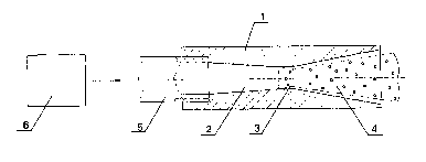
A liquid sprayer formed according to the first embodiment of the invention
(See Figs 1
to 5) comprises a casing 1 with a flow-through channel composed of axially
aligned portions
joined with one another. An inlet portion 2 is made in the form of a
converging tube with an
outlet opening joined to an inlet opening of a cylindrical portion 3. An
outlet portion 4 made
in the form of a conical diffuser comprises an inlet opening joined with an
outlet opening of
the cylindrical portion 3. A length of the cylindrical portion is 0.7 the
diameter thereof. An
apex angle of a cone defining the converging tube is 13° and an apex
angle of a cone defining
the diffuser is 20°.
The casing 1 is connected at the side of the inlet opening ~of the converging
tube to a
pipe union 5 of a pipeline of a liquid supply system. The liquid supply system
includes a
pump- or pressure-type liquid supercharger 6.
In a preferred embodiment (See Fig. 2) inlet edges of the converging tube
defining the
inlet portion 2 of the flow-through channel and outlet edges of the diffuser
defining the outlet
portion 4 are made rounded, with the radius of roundness being equal to the
diameter of the
cylindrical portion 3.
The liquid sprayer may include a chamber 7 (See Fig. 3) having a cylindrical
channel 8
whose inlet opening is communicating with an outlet section of the diffuser
(outlet portion 4).
A diameter of the cylindrical channel 8 is equal to four diameters of the
cylindrical portion 3
of the flow-through channel. The length of the cylindrical channel 8 measured
from the outlet
section of the diffuser to the outlet section of the chamber 7 is equal to ten
diameters of the
cylindrical pouion 3 of the flow-through channel. A perforated plate 9 is
located in the outlet
opening of the cylindrical channel 8 and attached to an end part of the
chamber 7 by means of
a special nut 10. A total cross-sectional area of holes in the perforated
plate 9 is 0.5 the cross-
sectional area of the cylindrical channel 8. The maximal size "d" of each of
the flow-through
holes in the perforated plate 9 is selected depending on the diameter "D" of
the cylindrical
portion 3 in accordance with the condition: 0.2 < d/D < 0.7.
Eight tangential openings 11 are formed in the wall of chamber 7 for ejecting
air from
the outside into the cylindrical channel 8 (See Figs 3 and 4). The tangential
openings 11 are
arranged in two cross-sectional planes of the cylindrical channel 8. Four
openings 11 are
symmetrically arranged in the cross-sectional plane of the channel 8 near the
outlet section of
the diffuser (outlet portion 4), and four other openings 11 are arranged in
the cross-sectional
plane of the channel 8 near the outlet section of the chamber 7.
IPEA/RlJ
N~M~IiEHHbIN IINC~'
CA 02441405 2003-09-19
WO 02/076624 PCT/RU02/00108
8
The sprayer may be equipped with a cylindrical chamber 12 (See Fig. 5)
arranged in
axial alignment with the casing 1, on the outside thereof. An annular passage
is formed
between the outer surface of the casing 1 and the inner surface of the chamber
12 and
communicated with a high-pressure gas source 13. The annular passage is
adapted for
supplying gas to the section of the outlet portion 4 of the flow-through
channel. A nozzle
located on an end part of the chamber is composed of a converging tube 14 and
a diffuser 15.
A liquid sprayer, according to the second embodiment of the invention (See
Figs 6 to 8),
comprises a casing 16 with a flow-through channel composed of sequentially
joined portions
axially aligned with one another. An inlet portion 17 is made in the form of a
conoid-shaped
converging tube with a radius of roundness of a side surface equal to the
diameter of a
cylindrical portion 18. A length of the cylindrical portion 18 joined with the
inlet portion 17 is
0.7 the diameter thereof. An outlet portion 19 formed as a conical diffuser
has an inlet
opening joined with the outlet opening of the cylindrical portion 18. An apex
angle of a cone
forming the diffuser is 20°. The conoid-shaped surface of the
converging tube (inlet portion
17) is joined with the surface of the cylindrical portion 18 at an angle of
2°. The outlet edges
of the diffuser forming the outlet portion 19 of the flow-through channel are
made rounded,
with a radius of roundness of the edges being equal to that of the cylindrical
portion 18.
The casing 16 is connected to a pipe union 20 of a pipeline of a liquid supply
system
including a liquid supercharger 21.
The outlet edges of the diffuser forming the outlet portion 19 are made
rounded, with a
radius of the roundness of the edges being equal to that of the cylindrical
portion 18.
In the preferred embodiment of the sprayer (See Fig. 7) the outlet opening of
the
diffuser (outlet portion 19) is communicated with a chamber 22 having a
cylindrical channel
23. Geometrical sizes of the cylindrical portion 18 are selected identical to
those of the first
embodiment of the sprayer (See Fig. 3). A perforated plate 24 is located in
the outlet opening
of the cylindrical channel 23 and attached to an end part of the chamber 22 by
means of a
special nut 25. The sizes of holes in the perforated plate 24 are selected
identical to those of
the first embodiment of the sprayer (See Fig. 3).
Eight tangential openings 26 are formed in the wall of the chamber 22 for
ejecting air
from the outside into the cylindrical channel 23 (See Figs 7 and 4).
Tangential openings 26
are arranged and oriented in the manner identical to that of the first
embodiment of the
sprayer.
CA 02441405 2003-09-19
WO 02/076624 PCT/RU02/00108
9
Another example of the sprayer according to the second embodiment of the
invention
may comprise a cylindrical chamber 27 (See Fig. 8) arranged coaxial with the
casing 16, on
the outside thereof. An annular passage formed between the outer surface of
the casing and
the inner surface of the chamber 27 is communicated with a high-pressure gas
source 28. The
annular passage is adapted for supplying a cocurrent gas flow to the outlet
section of the
outlet portion 19 of the flow-through channel. A nozzle on the end part of the
chamber is
composed of a converging tube 29 and a diffuser 30.
The operation of the sprayer designed in accordance with the first embodiment
of the
invention is carried out in the following manner.
Water is supplied under pressure by a supercharger 6 via a pipeline of a water
supply
system to a pipe union 5 connected to an outlet opening of the casing 1 of
said sprayer. Water
is delivered into an inlet opening of the converging tube (inlet portion 2),
where a high-
velocity liquid flow is generated with a uniform velocity profile over the
section thereof. The
liquid flow is advancing in the converging tube from the zone with a higher
static pressure
and a lower dynamic pressure to the zone with a lower static pressure and a
higher dynamic
pressure. This allows the conditions for the formation of vortex flows and
separation of the
liquid flow from the channel wall to be prevented.
The maximal liquid flow velocity at the outlet end of the converging tube is
selected
such that the static pressure at the outlet end of the converging tube is
decreased to the value
of the saturated liquid vapor pressure at the initial temperature (for water
PS~ ~ 2.3410-3 MPa
at t=20°C). The initial static water pressure upstream of the
converging tube is maintained at
the level not below the critical pressure sufficient for the development of
cavitation during
outflow into the atmosphere (P;~ ~ 0.23 MPa). The losses of kinetic energy
occurring during
passage of the liquid flow through the converging tube depend on the cone
angle of a cone
forming the conical surface of the converging tube. As the cone angle
increases from 6°, the
consumption of energy is initially increased to reach the maximal value at the
angle of ~ 13°
and is then decreased at the angle of ~ 20°. The optimal apex angle of
the cone forming the
converging tube is therefore selected between 6° and 20°.
Upon passage through the inlet portion 2 of the flow-through channel of the
sprayer, the
liquid flow is delivered into the cylindrical portion 3, where cavitation
bubbles are developed
for the period of time of ~ 10-4 = 10-5 s. The formation of bubbles during the
passage of water
flow through the cylindrical portion 3 is ensured in case the length of the
cylindrical portion
exceeds its radius to provide for predetermined time sufficient for the steady-
state cavitation.
CA 02441405 2003-09-19
WO 02/076624 PCT/RU02/00108
However, it is well known that hydraulic friction losses are increased at
substantially
increased length of the cylindrical channel. So under the practicable sprayer
service
conditions the length of the cylindrical channel may be restricted to the
value corresponding
to a diameter of the flow-through channel.
5 During passage of the liquid through the outlet portion 4 formed as a
diffuser the
cavitation bubbles are intensively growing and clapping and the liquid flow is
separated from
the diffuser wall. The flow is accelerated in the diffuser due to the
reduction in the density of
the liquid flow containing vapor and air bubbles. Because the static pressure
in an inlet zone
of the diffuser is low and is comparable to the cavitation pressure, a
directed air flow enters
10 from the outside into a cavity between the gas-drop jet and the diffuser
wall. Vortex flows
resulting from the countercurrent gas flow and liquid flow force out the
liquid flow from the
diffuser wall to reduce the friction energy losses. Also the formation of
vortex flows results in
active splitting of the liquid flow, which is further intensified by clapping
of the cavitation
bubbles during the expansion of the flow in the diffuser. Such processes occur
in case the
cone angle of the diffuser defining the outlet portion 2 of the flow-through
channel exceeds
the cone angle of the converging tube defining the inlet portion 4 of the flow-
through channel
of the sprayer. Optimal apex angles of the cone forming the diffuser are
between 8° and 90°.
Formation of vortex flows does not occur at the apex angles exceeding
90°. At the apex angles
less than 8° a gas blanket between the liquid flow and the diffuser
wall is practically lacking.
Along with the proper selection of optimal taper angles for the converging
tube and the
diffuser, a diameter of the diffuser outlet opening is important for effective
splitting of the
liquid flow. It is advisable to use the diameter of the diffuser outlet
opening exceeding the
diameter of the cylindrical portion 3 by 4 = 6 times. At a lesser diameter of
the diffuser outlet
opening the effect of vortex flows appears only slightly upon the liquid flow
and at a greater
diameter the dimensions of the sprayer are substantially increased.
The sprayer having the aforementioned sizes of the flow-through channel
provides for
the formation of a high-velocity fine-dispersed gas-drop jet at the minimal
losses of kinetic
energy.
When the diameter of the outlet opening of the pipe union S is essentially
greater than
the diameter of the cylindrical portion 3 of the flow-through channel, use is
made of a
converging tube having rounded inlet edges (See Fig. 2).
Such embodiment of the sprayer allows its dimensions to be decreased with
minimal
losses of kinetic energy for friction and formation of vortex flows. Optimal
radius of
CA 02441405 2003-09-19
WO 02/076624 PCT/RU02/00108
roundness of the converging tube edges is between 1 and 2.5 radius of the
cylindrical portion
of the flow-through channel. Increase in the radius of the rounded edges
results in increased
dimensions of the whole device, so the radius is preferably selected equal to
the diameter of
the cylindrical portion 3. With the liquid outflowing through the converging
tube having
rounded edges, the operational mode of the sprayer is not changed as a whole,
the cavitation
zones being localized in the inlet portion of the diffuser. The given
operational feature
intensifies cavitation in the liquid flow during acceleration thereof.
Implementation of the diffuser (outlet portion 4 of the flow-through channel)
with
rounded outlet edges (See Fig. 2) allows the steady state of the gas-drop jet
flowing from the
sprayer to be enhanced. With such embodiment of the sprayer, the jet generated
is free from
stationary and oscillatory deviations from a longitudinal axis of symmetry of
the flow-through
channel.
The radius of roundness of the diffuser outlet edges is also selected between
1 and 2.5
radius of the cylindrical portion 3 of the flow-through channel of said
sprayer. An increase in
I S the radius of roundness of the diffuser outlet edges results in the
reduced effect of air vortex
flows entering the diffuser on the process of splitting drops in the gas-drop
jet generated.
As a consequence, drop sizes in the gas-drop jet generated are increasing. On
the basis of the
aforementioned limitations, the radius of roundness of edges in the preferred
embodiment is
selected equal to the diameter of the cylindrical portion 3 of the flow-
through channel.
On flowing of the accelerated liquid-gas jet through the outlet section of the
diffuser
having outlet edges rounded to the optimal extent, axially symmetric toroidal
vortex air flows
are formed in the diffuser. Such toroidal structures are axially elongated and
do not give rise
to disturbances in the diffuser outlet portion.
When a chamber 7 with a cylindrical channel 8 (See Fig. 3) is used in the
preferred
embodiment of the sprayer, the gas-drop jet is expanded and droplets are
additionally split by
the perforated plate 9. While advancing through the channel 8, the jet is
expanded and
becomes stabilized along the length of the channel which is 10 to 30 diameters
of the
cylindrical portion 3 of the flow-through channel of the sprayer. At the given
range of lengths
for the cylindrical channel 8, the velocity leveling is provided over the
section of the gas-drop
jet on the one hand and the required jet velocity is maintained on the other
hand. Upon
collision against the perforated plate 9, the size of droplets in the gas-drop
jet is reduced on
the average by 2 = 3 times.
CA 02441405 2003-09-19
WO 02/076624 PCT/RU02/00108
12
The effect of the perforated plate 9 on the structure of the gas-drop jet
generated in the
flow-through channel of the sprayer is eliminated by providing free access of
air from the
outside to the diffuser outlet section. Such possibility is provided through
selecting a total
area of holes in the plate 9 in the range between 0.5 and 0.6 of the cross-
sectional area of the
cylindrical channel 8. An increase in the area of holes results in non-uniform
drop size
distribution over a section of the fine-dispersed flow generated and in the
possible occurrence
of separate liquid streams and gas inclusions (discontinuities in the liquid
flow) on the
periphery of the flow.
The optimal selection of diameters "d" of holes in the perforated plate 9
(according to
the condition: 0.2 < d/D < 0.7, where D is the diameter of the cylindrical
portion 3) provides
for time and spatially uniform splitting of the liquid flow into small
droplets. The selection of
hole sizes less than the optimal values results in "sticking" of liquid in the
perforated plate
holes due to the effect of surface tension forces. On the other hand, an
increase in the diameter
"d" of holes above the optimal value results in an increase in the sizes of
droplets in the
liquid-gas flow generated.
Tangential openings 11 (See Fig. 3) formed in the chamber 7 provide for
additional
vortex stabilization in the process of formation of a fine-dispersed gas-drop
jet, when the
liquid feed pressure is varied within a wide range (up to tenfold increase of
the initial nominal
level).
During operation of the sprayer the air is ejected from the outside into the
cylindrical
channel 8 via four tangential openings 11, which are symmetrically arranged by
pairs in two
cross-sectional planes of the cylindrical channel 8 of the chamber 7. The
ejection is caused by
the reduction of the static pressure (vacuum) at the diffuser outlet end, when
the gas-drop jet
is accelerated. The tangential orientation of the openings 11 formed in the
chamber 7 and their
symmetric arrangement in the two cross-sectional planes of the chamber 7, with
the first plane
extending near the diffuser outlet section and the second plane extending near
the outlet
section of the chamber 7, allows the ejected air flow to be uniformly swirled
around the gas-
drop jet. Tangential swirling of the incoming air reduces the effect of the
perforated plate 9 on
the flow in the cylindrical channel 8 and minimizes "sticking" of the liquid
in the holes of the
perforated plate 9. Also, said operational mode of the sprayer intensifies the
process of
intermixing the liquid drops with air across the flow section and,
consequently, increases the
homogeneity of drop concentration in the flow upstream of the perforated plate
9. Along with
CA 02441405 2003-09-19
WO 02/076624 PCT/RU02/00108
13
this, the possibility for occurrence of separate liquid streams affecting the
formation of a
homogeneous fine-dispersed gas-drop jet is eliminated.
The investigations disclosed that the optimal conditions for stabilizing a gas-
drop jet are
created by providing a certain ratio of the cross-sectional area of tangential
openings to the
total area of the effective section of the perforated plate 9, which is
between 0.5 and 0.9. The
number and arrangement of the tangential opening levels along the chamber 7
depend on the
requirements for uniform mixing of the liquid-gas flow.
Use of a chamber 12 (See Fig 5) in the construction of the sprayer provokes
further
splitting of drops in the generated cocurrent gas flow and increases the reach
of a fine-
dispersed gas-drop jet generated. A gas flow is generated through the outflow
of gas supplied
under the excessive pressure of 0.25 = 0.35 MPa from a high-pressure gas
source 13 into an
annular passage formed between the outer surface of the sprayer casing 1 and
the inner
surface of a chamber 12. The optimal ratio of the liquid flow rate through the
sprayer flow-
through channel and of the gas flow rate through the annular passage of the
chamber is
between 90 and 25.
A narrow directed fine-dispersed gas-drop jet is finally formed, when
cocurrent gas
flows and a preliminarily dispersed gas-drop jet are simultaneously
accelerated in the nozzle
of the chamber 12 composed of a converging tube 14 and a diffuser 15. While
the gas-drop jet
flows through the nozzle of the chamber 12, large liquid drops are split due
to the action of
the peripheral gas flow and additionally accelerated by said gas flow. At the
initial liquid
velocity of 45 m/s and at the initial gas velocity in the chamber 12 of up to
80 m/s, the
average velocity of drops in the generated gas-drop jet was ~ 30 m/s at a
distance of 3.5 m
from the outlet section of the chamber nozzle. The generated gas-drop jet had
sufficiently
homogeneous distribution of drop sizes over the jet flow section: drop sizes
in the central part
of the jet were 190 = 200 p., in the middle ammlar zone 175 = 180 ~. and in
the peripheral
annular zone ~ 200 ~ and more.
Operation of the sprayer designed according to the second embodiment of the
invention
(See Figs 6 to 8) is performed in the manner identical to that of the first
embodiment of the
invention. It differs only in more optimized formation of a gas-drop jet at
reduced longitudinal
dimension of the sprayer. According to the second embodiment of the invention,
the inlet
portion 17 of the flow-through channel of said sprayer is made conoid-shaped,
with radius of
roundness of the side surface being not less than radius of the cylindrical
portion 18 of the
flow-through channel. Such construction of the inlet portion allows the losses
of kinetic
CA 02441405 2003-09-19
WO 02/076624 PCT/RU02/00108
14
energy of the gas-drop jet for the formation of vortex flows in the converging
tube to be
decreased. The surface of the converging tube is continuously joined to the
cylindrical surface
of portion 18 to provide for acceleration of the liquid flow and exclude early
formation of
vortex flows upstream of the diffuser inlet end. Moreover, the continuous
reduction in the
effective section of the short conoid-shaped inlet portion 17 of the channel
causes the
cavitation centers to localize in the vicinity of the diffuser inlet section.
As a result the fine-
dispersed gas-drop jet of homogeneous concentration is generated at minimal
losses of
energy.
The results of investigations support the possibility of generating by means
of the
invention a steady-state fine-dispersed liquid flow at minimal consumption of
energy. The
flow generated retains the shape and size of its section at the distances of
up to 10 m, with
improved homogeneity of the drop concentration distribution being provided
over the flow
section.
Industrial applicability
The claimed invention may be employed in fire-prevention systems, as part of
processing equipment, for burning of fuel in heat engineering and transport,
as well as for
humidifying the environment and spraying disinfectants and insecticides. The
invention may
be employed as part of fire-fighting means in the stationary and mobile units
for suppressing
the fires occurred in different kinds of objects: in the rooms of hospitals,
libraries and
museums, in the ships and planes, as well as for suppressing the sources of
fire in the open
air, etc.
The claimed invention is explained through the aforementioned examples of
preferred
embodiments, however it must be understood by those skilled in the art that in
case of
industrial implementation of the invention insignificant modifications can be
made as
compared to the illustrated examples of embodiments without substantial
departing from the
subject matter of the claimed invention.