Note: Descriptions are shown in the official language in which they were submitted.
CA 02441942 2003-09-22
WO 02/076593 PCT/US01/32327
-1-
HYDROPHILIC HOLLOW FIBER ULTRAFILTRATION MEMBRANES
THAT INCLUDE A HYDROPHOBIC POLYMER AND
A METHOD OF MAKING THESE MEMBRANES
BACKGROUND OF THE INVENTION
The present invention relates to a filtration membrane and a method of
making this membrane. More specifically, this invention relates to a
hydrophilic hollow
fiber membrane that is formed from a hydrophobic polymer.
Membranes are thin-film barriers that allow certain components of a fluid
mixture to selectively pass tlzrough the barriers while discriminating against
the other
components to achieve separation. These membranes are typically formed from
polymers and are semipermeable. The specific physical shape or form of the
membranes
can vary, and can include flat sheets, tubular membranes, and hollow fibers.
The specific
use to which the membrane is to be put dictates the form selected for its
construction.
Membranes in the form of hollow fibers are currently used in a variety of
applications,
including dialysis, gas separation, ultrafiltration, microfiltration, and
nanofiltration.
Polyvinylidene fluoride (PVDF) based membranes have good mechanical
strength and excellent chemical stability, particularly to free chlorine
attack.
Unfortunately, membranes made of PVDF homopolyzner are hydrophobic, and water
cannot wet the surface of a hydrophobic PVDF membrane in the absence of a
surfactant.
Thus, the hydrophobic nature of PVDF membranes imposes an enormous resistance
to
water permeation to give a low water flux. In addition, hydrophobic PVDF
membranes
often suffer from a severe fouling problem due to non-selective absorption of
solutes at
the hydrophobic membrane surface to further lower permeate flux.
In order to improve the hydrophilicity ofPVDF membranes and to reduce
membrane fouling, chemical surface modification has been used to prepare
hydrophilic
PVDF based membranes. One method of modifying a PVDF membrane is by first
reducing the PVDF membrane with NaOH and NaSzO41 followed by oxidizing it with
NaOCI, creating a more hydrophilic membrane.
An alternative method of chemical surface modification that has been
proposed involves using calcined alumina in particle form to replace NaOH to
catalyze
an elimination reaction of hydrofluoric acid (HF) from the PVDF backbone to
give a
double bond. A subsequent modification reaction is then completed by reaction
either
CA 02441942 2003-09-22
WO 02/076593 PCT/US01/32327
-2-
with water or with a partially hydrolyzed polyvinyl acetate so as to form a
hydrophilic
membrane.
Still another method of modifying the chemical surface of a PVDF
polymer involves reacting PVDF powder with KOH in methanol, followed by
reacting
it with 98% H2S04 to give a hydrophilic hydroxyl-containing PVDF membrane.
This
modified membrane has less fouling than before modification.
It has also. been suggested to graft an epoxide-containing polymer to a
PVDF membrane in order to improve membrane mechanical strength and
hydrophilicity.
Still further, grafting a polymer containing a positively charged organic
phosphonium
compound onto the PVDF membrane surface so as to make it more hydrophilic has
also
been proposed. In addition, it has been proposed to covalently bond quaternary
ammonium groups to positively charged PVDF membranes. Such a membrane has been
used for pharmaceutical separations. Still further, others have suggested a
process for
preparing hydrophilic microporous PVDF membranes by grafting a water-soluble
polymer, such as polyethylene glycol dimethacrylate, to the hydrophobic
membrane
substrate surface by irradiation means, such as ultraviolet irradiation.
While chemical modification permanently adds hydrophilic groups to the
PVDF membrane by covalent bonding, the membranes created by such modification
have
disadvantages. The modification reaction often has a low yield and poor
reproducibility.
In addition, many times toxic chemicals 'are used in the modification
reaction. Still
further, the process may be lengthy and costly.
An alternative approach to improving the hydrophilicity of PVDF
membranes is to blend a hydrophilic polyiner with hydrophobic PVDF. Components
that
can be blended with PVDF include cellulose acetate, sulfonated polysulfone,
glycerol
monoacetate, glycerol diacetate, glycerol triacetate, and sulfonated
polyetherketone.
The polymer blend approach has a lower cost and higher efficiency than
chemical modification. However, the polymer blend approach has some drawbacks.
Because there is no covalent bonding between the PVDF and the hydrophilic
components, it is often found that membrane performance deteriorates with time
due to
a gradual loss of hydrophilic components from the membrane matrix.
Another method that has been suggested is surface coating. For instance,
a hydrophobic PVDF membrane may be coated with a water-insoluble vinyl alcohol-
vinyl acetate copolymer. The coating layer however is more vulnerable to free
chlorine
CA 02441942 2003-09-22
WO 02/076593 PCT/US01/32327
-3-
attack than PVDF. Therefore, after frequent exposure to a cleaning reagent
containing
free chlorine, such as bleach, the hydrophilic coated membrane becomes
hydrophobic.
A water-soluble polymer, such as polyvinylpyrrolidone (PVP), has not
been used as a part of a polymer blend to make a hydrophilic PVDF membrane
because
the water-soluble polymer is washed out of the membrane by water, as is taught
by U.S.
Patent No. 5,151,193. U.S. Patent No. 5,834,107 (the '107 patent) contradicts
this
teaching but is technically inaccurate. If the PVDF membrane disclosed in the
'107
patent contained 1-30% by weight polyvinylpyrrolidone, as claimed, then it
would be
hydrophilic, as represented in the '107 patent. However, the membrane of the
'107
patent actually is not hydrophilic and does not contain 1-30% by weight
polyvinylpyrrolidone. Evidencing the fact that this membrane is not
hydrophilic, the
'107 patent teaches that its membrane must be exposed to a wetting agent, such
as
hydroxypropylcellulose, in order to make it hydrophilic. This would not be
necessary
if the membrane was really hydrophilic. What actually happened in the making
of the
membrane of the ' 107 patent was that PVP was added into the membrane casting
solution
as a pore former and then washed out of the membrane by water in a coagulation
bath
during membrane formation. In fact, such a process is discussed in U.S. Patent
Nos.
5,151,193 and 4,399,035, where PVP is used as an additive to fabricate a PVDF
membrane.
Still furtlier, in the '107 patent, the membrane was cast in an environment
having a relative huinidity as high as 100% at 27 C, but water vapor pressure
was not
increased by increasing teinperature. Instead, this patent discloses using a
longer
exposure time of the cast membrane to humid air. This is disadvantageous
because
longer exposure times of the cast membrane to humid air prohibits membrane
production
at a higher speed. For instance, if the exposure time is 2 minutes, as
suggested in the
'107 patent, and the membrane casting speed is 10 ft/min, it requires 20 feet
of exposure
space. Thus, the process of the '107 patent requires a huge capital -
investment to make
a membrane casting machine to meet the requirement of a two minute exposure
time.
Furthermore, gravity will cause the extruded fiber to break before it reaches
the
coagulation bath if the distance between the spinneret and the coagulation
bath is too
long.
In order to overcome the deficiencies found with the membranes discussed
above, a membrane with strength and 'hydrophilicity and a process for making
the same
CA 02441942 2006-05-16
-4-
are needed. More specifically, a membrane whose hydrophilic qualities are not
washed
away with water or bleach is needed. Still further, a process for. making such
a
membrane that is efficient, has a good yield, and is easily reproducible is
needed. In
addition, a better way to control the humidity of the environment where the
membrane is
created is needed in order to improve the productivity of membrane
nianufacturing.
SUMMARY OF THE INVENTION
It is an object of the present invention to provide a hy-dr-ophilic
membrane that has the mechanical strength and chemical stability of a PVDF
membrane
and a method of making this membrane.
It is another object of the present invention to control humidity during
membrane formation so as to improve membrane structure and performance.
According to the present invention, the foregoing and other objects are
achieved by a hydrophiliemembrane that includes a hydrophobic polymer and a
water-
soluble polymer-metal complex. This membrane is made by heating a mixture of a-
hydrophobic polymer, an additive, and a solvent, adding a metal compound and a
water-
soluble polymer to the mixture, and heating and mixing the solution. The water-
soluble
polymer forms complexes with the metal compound and homogeneously entangles
with
the dissolved hydrophobic polymer to form a viscous dope. The dope is extruded
though
an annular orifice to form a hollow fiber. The fiber is put in an environment
having a
controlled humidity so that it becomes partially solidified, and then, the
fiber is put in a
coagulation bath. The hollow fiber is formed by phase inversion in the
coagulation bath
and is collected with a take-up wheel partially immersed in a leaching bath.
In accordance with an aspect of the present invention, there is provided a
hydrophilic hollow fiber membrane comprising: a hydrophobic polymer; and a
water-
soluble polymer transition metal complex entangled with said hydrophobic
polymer,
wherein said water-soluble polymer is selected from the group consisting of
polyvinylpyrrolidone, polyvinylpyrridine, and combinations thereof.
In accordance with another aspect of the present invention, there is
provided a method of making a hydrophilic hollow fiber membrane, comprising:
mixing
a hydrophobic polymer and a solvent to form a mixture; heating said mixture to
form a
CA 02441942 2006-05-16
. ~
-4a-
solution; adding a transition metal compound and a water-soluble polymer
selected from
the group consisting of polyvinylpyrrolidone, polyvinylpyrridine, and
combinations
thereof to said solution; heating and mixing said solution, wherein said water-
soluble
polymer forms complexes with said transition metal containing compound and
homogeneously entangles with said dissolved hydrophobic polymer to form a
viscous
dope; and extruding said dope through an annular orifice to form a hollow
fiber.
Additional objects, advantages, and novel features of the invention will
be set forth in part in the description which follows, and in part will become
apparent to
those skilled in the art upon examination of the following, or may be learned
from
practice of the invention. The objects and advantages of the invention may be
realized
and attained by means of the instrumentalities and combinations particularly
pointed out
in the appended claims.
BRIEF DESCRIPTION OF THE DRAWINGS
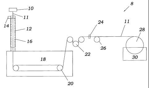
FIG. 1 is a schematic representation of a hollow fiber spinning system
used in the making the membrane of the present invention;
CA 02441942 2003-09-22
WO 02/076593 PCT/US01/32327
-5-
FIG. 2 is an infra-red spectra of typical hollow fiber membranes obtained
by the method of the present invention;
FIG. 3 is an Electron Spectroscopy for Chemical Analysis (ESCA)
spectrum of a hollow fiber membrane obtained from the method of the present
invention
is outlined in Example 1;
FIG. 4 is a plot showing permeate flux of hollow fiber membranes of the
present invention as a function of time;
FIG. 5 is a scanning electron microphotograph of the cross section of a
hollow fiber membrane obtained from the method of the present invention as
outlined in
Example 1;
FIG. 6 is a scanning electron microphotograph of the outer surface of a
hollow fiber membrane obtained from the method of the present invention as
outlined in
Example 1;
FIG. 7 is a scanning electron microphotograph of the inner surface of a
hollow fiber membrane obtained from the method of the present invention as
outlined in
Example 1;
FIG. 8 is a scanning electron microphotograph of a hollow fiber
membrane obtained from the method of the present invention as outlined in
Example 4;
FIG. 9 is a scanning electron microphotograph of a hollow fiber
membrane obtained from the method of the present invention as outlined Example
8;
FIG. 10 is a scanning electron microphotograph of a hollow fiber
membrane obtained from the method of the present invention as 'outlined
Example 8; and
FIG. 11 is a scanning electron microphotograph of a hollow fiber
membrane obtained from the metliod of the present invention as outlined
Example 9.
DETAILED DESCRIPTION OF THE PREFERRED EMBODIMENT
The membrane of the present invention is a hydrophilic hollow fiber
membrane. It includes a hydrophobic polymer as a major component and a water-
soluble
polymer-metal complex as a minor component. The water-soluble polymer-metal
complex forms a network and uniformly entangles with the hydrophobic polyiner
network in the membrane matrix. The membrane of the present invention is
insoluble
in water, and the water-soluble polymer in'the membrane cannot be removed from
the
membrane by water either during or after the membrane's formation.
CA 02441942 2003-09-22
WO 02/076593 PCT/US01/32327
-6-
The membrane of the present invention is made by preparing a
homogenous casting solution from a hydrophobic polymer, a compatible water-
soluble
polymer, and at least one metal containing compound. More specifically, an
additive and
a hydrophobic polymer are dissolved in a solvent and mixed at an elevated
temperature
using a Myer mixer from Myer Engineering, Inc., 8376 Salt Lake Avenue, Bell,
California 90201. The additive may be lithium chloride, a metal containing
compound,
or polyethylene glycol. The viscous solution obtained is then mixed with an
additional
metal containing compound, which may but need not be a different metal
containing
compound, and a water-soluble polymer at an elevated temperature for a period
of time
sufficient to produce a brown, homogeneous and viscous solution.
Alternatively, all of
the metal containing compounds to be used, the hydrophobic polymer, and the
water-
soluble polyiner may be added to the solvent at the same time and then mixed
at an
elevated temperature for several hours using a Myer mixer to give a brown
viscous
solution.
The viscous solution or dope has a viscosity of about 100 to 600,000
centipoise (cp) at about 25 C. The viscous dope, which is the membrane casting
solution, is extruded through an annular orifice to form a hollow fiber. More
specifically,
it can be pressurized from a storage tank into a gear pump and then extruded
through an
annular orifice of a spinneret, generally the tube-in-orifice type, into a
hollow core
extrudate fiber. Internal bore fluids are often co-extruded within the hollow
fiber
membrane to form the bore or lumen of the hollow fiber. Following extrusion,
the
polymeric membranes of the present invention are formed by a phase inversion
process
induced by diffusion of water or water vapor from outside the hollow fiber and
a bore
fluid from inside the hollow fiber membranes.
More specifically, hollow fiber membranes may be made from the
meinbrane casting solution using a hollow fiber spinning system, as shown in
FIG. 1 and
designated broadly by the numeral 8. This systeni includes a spinneret 10 that
feeds spin
fiber 11 made from the membrane.casting solution to a cylindrical colunm 12.
An inlet
14 for water is located at the top of cylindrical column 12 and causes a
waterfall 16 to be
fornied in the interior surface of cylindrical column 12. Waterfall 16
surrounds the
extruded hollow fiber 11 to provide an environment with a controlled humidity.
Water
from waterfall 16 enters a coagulation bath 18, and the membrane casting
solution 11 is
spun through coagulation bath 18 using two power driven wheels 20 that are
immersed
CA 02441942 2003-09-22
WO 02/076593 PCT/US01/32327
-7-
in the coagulation bath. The fiber 11 then exits the coagulation bath and is
talcen to a
godet station 22. From there, it passes through a laser scan micrometer 24.
Wheels-26
and other wheels not shown move fiber 11 along the path of the spinning
system. A take-
up wheel 28, which is partially immersed in a leaching bath 30, directs the
extruded
hollow fiber 11 into leaching bath 30. The fiber 11 wraps around take-up
whee128 so
as to be collected.
The water-soluble polymer, PVP, has a resonance structure with a
negative charge localized at the oxygen atom and a positive charge localized
at the
nitrogen atom, as shown below.
(1)
The water-soluble polymer reacts with the metal containing compound in
the solution to form a water-soluble polymer-metal complex, as shown in the
following
reaction. The reaction shown below uses ferric chloride as the metal
containing
compound and PVP as the water-soluble polymer:
CA 02441942 2003-09-22
WO 02/076593 PCT/US01/32327
-8-
OH
(1) FeC13 + o\ - -- ;
n +~ 0 (2) Ha0 1~1/ Fe
0 +
, 0---~----
CI
(2)
wherein n is an integer.
By using a metal containing compound in the casting solution, the water-
soluble polymer is allowed to react with the metal of the metal containing
compound to
form a three dimensional network and uniformly interpenetrate the network of
the.
hydrophobic polymer in the membrane casting solution. The water-soluble
polymer is
permanently retained in the membrane matrix to give a hydrophilic membrane.
The rate of phase inversion is controlled, at least in part, by utilizing a
bore fluid and/or a coagulation bath. An internal bore fluid is co-extruded in
the lumen
of the fiber, helping to solidify and form the inner core of the hollow fiber
membrane.
The extruded hollow fiber is then passed through a bath where the solvent is
replaced
with a nonsolvent, such as water, and the fiber is allowed to further
solidify. The
membrane pore size can be regulated, at least in part by controlling the
solvent content
in the coagulation bath and/or in the bore fluid.
The humidity of the environment in which a membrane is cast, prior to
quenching it in a coagulation bath, has a significant impact on membrane
structure and
performance. Before the fiber enters the coagulation bath, it is put in an
environment
having a controlled humidity so that the fiber becomes partially solidified.
The hollow
fiber is then formed by phase inversion in the coagulation bath, where
solidification
fu.rther takes place by mass transfer to replace the solvent with a
nonsolvent.
CA 02441942 2003-09-22
WO 02/076593 PCT/US01/32327
-9-
Another aspect of the present invention is a method for controlling the
iinpact of humidity on membrane structure and performance in the space between
the
spinneret and the coagulation bath. This space is referred to as the airgap.
The greater
the airgap the more the polymer is cured. In order to control humidity and
temperature
in the airgap, a casing may be used between the spinneret and the coagulation
bath,
allowing nitrogen to pass through a water trap to control water vapor pressure
in the
casing. Higher water vapor pressure is achieved using a waterfall surrounding
a newly
cast membrane at various temperatures. Water vapor pressure in column 12 is
controlled
by water temperature. The water vapor reaches equilibrium with water falling
along the
interior surface of the column 12. This colunm 12 with waterfall 16 may or may
not be
used when preparing fiber 11 depending upon the desired membrane structure and
performance.
The airgap environment has a relative humidity of about 0 to 100% and
a temperature range from about 0 to 100 C. When no water is in column 12, the
humidity of the colunm may be between about 0 to 100%. Preferably, the
hurriidity is
about 40 to 70%. Most preferably, the humidity is about 50 to 60%. When column
12
has no water, the airgap temperature is about 5 to 35 C. Preferably, it is
about 10 to
250C. Most preferably, it is about 20 to 25 C.
When humidity is provided in column 12 through waterfall 16 at the
interior surface of column 12, the column is about to obtain 100% relative
humidity at
various temperatures. When water trickles through column 12, the humidity is
about 50
to 100%. Preferably, it is about 70 to 100%. Most preferably, is it about 80
to 100%.
The water column temperature is about 0.2 to 100 C. Preferably, the water
column
temperature is about 20 to 100 C. Most preferably, the water column
temperature is
about 50 to 100 C.
The coagulation or gelation bath is comprised of 0-60% solvent and is at
a temperature of about 0.2 to 100 C. Preferably, its temperature is about 20
to 80 C, and
most preferably, its temperature is about 50 to 70 C.
After leaving the coagulation bath, the fibers are leached for a period of
approximately 24 hours in a leaching bath comprised of a nonsolvent, such as
water, in
order to remove the remaining solvent from the fibers. After leaching, the
fibers are
placed in a glycerin and nonsolvent bath for a period of approximately 24
hours. The
glycerin acts as a membrane pore radius-maintaining agent by filling the pores
of the
CA 02441942 2003-09-22
WO 02/076593 PCT/US01/32327
-10-
finished membrane to prevent them from 'collapsing during storage prior to use
in a
filtering device.
The leaching bath is a nonsolvent bath having a temperature of about 0.1
to 100 C. Preferably, this temperature range is between about 20 to 80 C, aild
most
preferably, the leaching bath has a temperature of between about 50 to 70 C.
The hollow fiber is formed at a fiber spinning speed of about 5 to 300 feet
per minute (ft/min). Preferably, the fiber spinning speed is about 50 to 250
ft/min. Most
preferably, the fiber spinning speed is about 100 to 200 ft/min.
The hydrophobic polymer is a synthetic polymer capable of forming a film
or fiber. The hydrophobic polymer may be, but is not limited to,
polyvinylidene fluoride
(PVDF), polysulfone, polyethersulfone, polyetherketone, polypropylene,
polyethylene,
or combinations thereof.
The water-soluble polymer is a polymer ligand capable of forming
complexes with a variety of metals. The water-soluble polymer may be, but is
not
limited to, polyvinylpyrrolidone (PVP), polyvinylpyrridine, or combinations
thereof.
The metal compound is an electron acceptor that is capable of forming
,complexes with a variety of ligands. The complexing metal may be any
transitional '
metal such as iron, cobalt, nickel, copper, zinc, manganese, or chromium.
Preferably, the
metal complexing agent is ferric chloride. Preferably, the membrane of the
present
invention includes PVDF and an iron-PVP complex.
There are many acceptable solvents which can be used in the solution of
this invention, and the solvent can be either protic or aprotic. Suitable
solvents are those
which are capable of solubilizing the hydropllobic polymer. The solvent in
which the
components of the membrane are mixed preferably is a polar solvent and may be,
but is
not limited to, dimethylacetamide, N-methyl-pyrrolidone (NMP), dimethyl
forniamide,
dimethylsulfone, trialkylphosphate, or combinations thereof. The bore fluid
generally
comprises water, and preferably comprises a mixture of water and a portion of
the same
solvent initially used as the solvent in the polymer mixture. The function of
the bore
fluid is to assist in the formation of the fibers from the inside out, whereby
the inner wall
of the fiber begins to coagulate as it comes into contact with the bore fluid.
As with the
bore fluid, the fluid in the coagulation bath generally comprises water, and
preferably
comprises a mixture of water and a portion of the same solvent used in making
the
polymer mixture.
CA 02441942 2003-09-22
WO 02/076593 PCT/US01/32327
-11-
The membrane of the present invention is for use in filtration. This
membrane is resistant to fouling and has an excellent chemical stability,
particularly to
chlorine attack. The hollow fibers having a separation barrier layer at the
inner surface
of the fiber can be operated in an inside-out flow mode, while the hollow
fibers having
a separation barrier layer at the outer surface of the fiber can be operated
in an outside-in
flow mode. This membrane can be used for microfiltration, ultrafiltration or
reverse
osmosis processes. Preferably, it is used for ultrafiltration. The water-
soluble polymeric
component of the membrane of the present invention is very stable to chlorine
attack and
is not washed out of the membrane matrix with water or bleach comprised of
12.5%
sodium hypochlorite.
The membrane of the present invention has a tensile strength of about 200
to 700 psi. This membrane has a water flux of about 100 to 1500 gallons per
square foot
per day (gfd) at about 40 psi. It has a rejection towards a 150 k Dextran
molecular
weight 'marker ranging from about 5% to 99.9%. It is suitable for a variety of
applications, including removal of oil from oily industrial wastewater.
As is known in the industry, fibers spun using a spinneret, such as
described above, can have wall thicknesses and outer diameters according to
the
specifications of the spinneret utilized. According to the present invention,
the hollow
fiber wall thickness can be widely varied, and is preferably in the range of
about 5 to
about 15 mils. The outer diameter measurement can also vary widely, and
preferably
ranges from about 10 to about 750 mils. It is understood that these values can
easily be
varied to achieve the desired properties of the end product membrane. The
diameter of
the formed hollow fiber may be monitored using a laser scan micrometer.
In one embodiment of the present invention, no waterfall column was used
to control humidity in the space between the spinneret and the gelation bath.
The
membrane casting solution described above was pressurized from a storage tank
into a
gear pump. It was in turn extruded through an annular orifice of a spinneret
10 into a
fiber 11. A bore fluid was applied in a lumen to keep the fiber hollow. The
extruded
fiber 11 was allowed to fall freely for a certain distance from 0 to 60 inches
in the airgap
before reaching coagulation bath 18 containing water as a coagulating agent.
The
quenched fiber was wrapped several times on the two power-driven wheels 20
five feet
apart in the coagulation bath 18. The bath temperature was varied between - 13
to
1 00 C. After passing through the coagulation bath, the hollow fiber 11 was
allowed to
CA 02441942 2003-09-22
WO 02/076593 PCT/US01/32327
-12-
pass through a godet station 22 and a laser scan micrometer 24 to measure
vertically and
horizontally the outside diameter of the fiber. The fiber 11 was then
collected by a take-
up wheel 28, partially immersed in leaching bath 30. The fiber diameter was
controlled
from 2 to 200 mil depending on the needs of the membrane being created. The
hollow
fiber membrane formed had a yellow color due to the presence of iron in the
membrane.
' Morphology of a typical hollow fiber obtained in the present invention
was examined using a Scanning Electron Microscope (SEM). Figs. 5-7 show
microphotographs of a hollow fiber membrane obtained from Example 1, discussed
infra,
ofthe present invention. There are finger-like voids near the inner surface as
shown in
Fig. 5. The finger-like voids occupy about 40% of the cross section. There is
a relatively
dense layer on top of the finger-like void region to provide a good mechanical
strength.
This membrane has a relatively open and rough outer surface as shown in Fig.
6, and a
relatively dense and smooth inner surface, as shown in Fig. 7. This is an
ideal structure
for an inside-out hollow fiber membrane. The smoother and tighter inner
surface
provides a good barrier for separation and for minimizing fouling due
to.physical
adsorption of solutes and deposition of suspended particles in a feed
solution. The rough
and open outer surface allows permeation resistance to be reduced, thus
increasing
permeate flux.
Infrared spectra of a typical hollow fiber membrane obtained in Example
1 of the present invention is presented in Fig. 2, Spectrum A. The FT-IR
spectra of the
same fiber as shown in Spectrum A treated with bleach and a hollow fiber
prepared from
PVDF without any PVP and ferric chloride as additives in the membrane casting
solution
are also shown in Fig. 2, as Spectrum B and C, respectively. These three
different fiber
samples used to obtain the infrared spectra shown in Fig. 2 were thoroughly
cleaned witli
reverse osmosis water and dried at 120 C overnight before taking the infrared
spectra
under the same condition. Clearly, no peak was observed around 1700 cm' from
Spectruxn C, indicating there is no carbonyl in the hollow fiber made of PVDF
alone as
expected. No peak was observed around 3400 cm indicating that there is no
hydroxyl
group in this PVDF membrane. In contrast to Spectrum C, strong peaks between
1600
and 1750 cm' were observed in Spectrum A, indicating the presence of carbonyl
in the
membrane. In Spectrum A, a moderate peak at 1550 cm' was also observed. The
presence of a 1650 crn 1 peak in Spectrum A is consistent with formation of
some kind
of complex between PVP and iron in the membrane. A very broad and strong peak
at
CA 02441942 2003-09-22
WO 02/076593 PCT/US01/32327
-13-
about 3400 cm"' was observed in Spectrum A, indicating the presence ofhydroxyl
groups
in the membrane.
In order to prove whether the PVP was permanently anchored into the
PVDF membrane matrix, an experiment was carried out by immersing the hollow
fiber
obtained from Example 1, discussed infra, into a bleach containing 12.5% (wt.)
sodium
hypochlorite at room temperature for one week. For comparison, a control
experiment
was also carried out using a polysulfone hollow fiber membrane under an
identical
condition described above.
After being immersed in the bleach (chlorine) for one week, the
polysulfone membrane turned into a white powdery material due to the chemical
degradation of polysulfone. It is well known that polysulfone is much more
stable than
PVP due to the presence of an electron withdrawing sulfone group in the
backbone of
polysulfone. If the condition used can cause polysulfone to decompose; it will
definitely
cause PVP to decompose. This result indicates that the condition used is
adequate to
show chlorine impact on the structure and performance of a membrane containing
PVP
as a hydrophilic component.
Afterbeing immersed in the bleach (chlorine) for one week, the membrane
of the present invention was rinsed thoroughly with reverse osmosis water for
48 h, then
the hollow fiber was dried and analyzed with infrared spectroscopy. A FT-IR
spectrum
obtained from such a chlorine treated sample shows that strong peaks between
1600 and
1750 cm 1 remain after such a harsh treatment with bleach as displayed in
Spectrum B in
Fig. 2. However, the shape of the peaks in the carbonyl region of Spectrum B
changed
to a certain degree compared to the same region of Spectrum A in Fig. 2. The
intensity
(height) of the peaks around 1650 cm' were reduced compared to the peaks near
1720
cm', suggesting that the number of carbonyl groups associated with iron was
reduced
after the chlorine treatment. As a result, the peak was shifted to a slightly
higher wave
number attributed to the carbonyl not associated with any iron. The chlorine
treatment
also resulted in a change in relative intensity of a 3050 cm'1 peak to a 2950
cm' peak.
In Spectrum A, a 3050 crn 1 peak is weaker than a 2950 cm-' peak. After the
chlorine
treatment, the relative intensity of a.3050 cm"' peak to a 2950 cm I pealc is
reversed and
becomes the same as that observed from Spectrum C of the hollow fiber having
no PVP
at all, i.e., a 3050 cm' peak is stronger than a 2950 cm 1 peak in Spectra B
and C. This
result clearly shows that the chlorine treatment has an observable impact on
chemical
CA 02441942 2003-09-22
WO 02/076593 PCT/US01/32327
-14-
structure of the hollow fiber obtained in the present invention, but it is not
enough. to
destroy the membrane. Shoulder pealcs adjacent to a strong pealc at 1720 cm'
in
Spectrum B are significant.
An even more severe treatment is shown in Example 2, discussed infra.
This severe treatment involved immersing the hollow fiber membrane in a bleach
containing 12.5% sodium hypochlorite at a room teiuperature for one month, and
the
results showed no significant change in tensile strength of the hollow fiber
(see Table 3
in Example 2). In addition, immersion of the hollow fiber obtained from
Example 1 in
a solution containing 200 ppm chlorine for one week showed no effect at all on
the IR
spectrum of the membrane. These results indicate the hollow fiber membrane
obtained
in this invention is very stable to chlorine attack. After the chlorine
treatment, the hollow
fiber remained the original yellow color, suggesting the presence of iron in
the
membrane. The results discussed above suggest that the remarkable stability of
the
hollow fiber membrane obtained in the present invention is related to the
presence of iron
in the membrane, because positively charged iron has an ability to withdraw
electrons
and thus stabilize the membrane.
A broad and moderate peak at about 3400 cm' was also observed in
Spectrum B, indicating the presence of hydroxyl groups in the membrane. The
samples
used for obtaining Spectrum A, B, and C in Fig. 2 were prepared together under
an
identical condition, and the spectra were also taken together under the saine
conditions.
Although these three membrane samples were exposed to the same atmosphere, the
intensities of hydroxyl band observed at about 3400 cni 1 in Fig. 3 are quite
different.
The intensity of 3400 cm' peak has the following order for.these three
membranes, A>
B> C, suggesting that the membrane having Spectrum A has more hydroxyl groups
than
the others in Fig. 2, thus it is more hydrophilic' than the chlorine treated
membrane, as
displayed in Spectrum B. This finding is consistent with the water flux data
shown in
Table 3 of Example 2, discussed infra. The membrane without PVP-metal
complexes
(Spectrum C) is simply hydrophobic.
In order to confirm the presence of iron in the membrane, the hollow fiber
obtained in Example 1 was analyzed by ESCA. A typical ESCA spectrum of a
hollow
fiber obtained from Example 1 is shown in Fig. 3. A signal detected at a
binding energy
of 711 ev was attributed to 2p electron of iron, clearly indicating the
presence of iron at
the membrane surface. The chlorine treated samples having. Spectrum B in Fig.
2, were
CA 02441942 2003-09-22
WO 02/076593 PCT/US01/32327
-15-
also analyzed by ESCA along with the hollow fiber prepared from PVDF alone as
a
control. Surface compositions of the hollow fiber membranes obtained from ESCA
are
given in Table 1. .
TABLE 1
Surface PVDF Fe/PVP/PVDF Fe/PVP/PVDF- Fe/PVP/PVDF
Composition Hollow Fibera Hollow Fiberb Hollow Fiber Hollow Fiberd
C 51.86 55.27 48.68 48.99
0 7.04 13.94 11.70 6.12
F 38.29 22.86 32.88 42.75
N 2.08 1.67 0.94 0.24
Fe 0 5.29 5.13 1.42
S 0.05 0.17 0.12 0
C l 0.11 0.66 0.48 0.27
Na 0.50 0.08 0 0.14
Ca 0.05 0.06 0.06 0.06
TOTAL 100 100 99.99 99.99
a. Hollow fiber membrane prepared from PVDF alone.
b. Hollow fiber membrane obtained from Example 1.
c. Hollow fiber membrane obtained in Example 1 was immersed in an aqueous
solution containing
200 ppm sodium hypochlorite at room temperature for one week.
d. Hollow fiber membrane obtained in Example 1 was immersed in an aqueous
solution containing
12.5% wt. sodium hypochlorite at room temperature for one week.
As expected the atomic percentage of iron is zero at the surface of the
hollow fiber membrane prepared from the PVDF alone without ferric chloride and
PVP
as additives. But, it is unexpected to detect oxygen and nitrogen at the
surface of the
hollow fiber membrane. The reason for this is not fully understood at this
point in time.
In contrast, the atomic percentage of iron is 5.29% at the surface of a hollow
fiber
membrane prepared from PVDF with ferric chloride and PVP as additives. A post
treatment of the membrane with an aqueous solution containing 200 ppm sodium
hypochlorite has a negligible effect on the iron concentration at the membrane
surface
but a significant effect on the surface concentrations of carbon, fluoride,
oxygen and
nitrogen. It should be noticed that the ratio of oxygen to nitrogen in the
hollow fibers
prepared from ferric chloride, PVP and PVDF (Fe/PVP/PVDF) is much higher than
that
in the fiber- prepared from PVDF alone. For a hollow fiber of the present
invention
CA 02441942 2003-09-22
WO 02/076593 PCT/US01/32327
-16-
prepared from ferric chloride, PVP and PVDF, the atomic percentage of iron at
the
membrane surface remained as high as 1.42% even after a severe post treatment
by
immersing the membrane in a pure bleach containing 12.5% wt. sodium
hypochlorite at
room temperature for a week. This result suggests that the iron is strongly
associated
with the membrane and plays a crucial role to make the membrane stable to
chlorine
attack, which is consistent with the ESCA result. The fiber color, the ESCA
spectra and
the quantitative analysis on concentration of iron, nitrogen and oxygen are
consistent
with the infrared spectra of the hollow fiber membranes discussed above,
indicating the
presence of iron and PVP in the PVDF based hollow fiber membrane. The iron has
three
positive charges (Fe3), PVP itself is soluble in water, thus the presence of
PVP and Fe3l
in the membrane matrix provides the membrane with a hydrophilic surface.
Carbonyl and nitrogen in an amide are good ligands which can fonn
complexes with a variety of metals. Based on the infrared spectra in Fig. 2,
the ESCA
spectrum in Fig. 3, and the data in Table 1, a complex formed from iron and
PVP is
shown in reaction (2), supra. Polyvinylpyrrolidone, in which only one
pyrrolidone
moiety is- drawn, has a resonance structure, with a negative charge located at
the oxygen
atom of the carbonyl group. It can behave as a good ligand to fonn a complex
with iron
as shown in reaction (1). The hydroxyl ligand of the iron complex proposed in
reaction
(2) is consistent with the broad peak at about 3400 cm' in Spectrum A and B in
Fig. 2.
The coordination of a carbonyl group with iron is consistent with the peak at
1650 cm i
in Spectrum A, in Fig. 2. The intensity change of the peak at 1650 cm 1 and a
shift of
carbonyl stretching vibration observed in Spectrum B to a sliglitly higher
wave number
after a chlorine treatment is consistent with the complex shown in reaction
(2). The
chlorine treatment may alter the nature of PVP-iron complex, thus resulting in
changes
in IR spectrum at 1650 cm 1, 1550 cm', 1720 cm'1, 2950 cm', 3050 cm'' and 3400
cni-1,
respectively.
Chlorine resulting as a ligand is consistent with the ESCA data presented
in Table 1. The Cl concentration at the membrane surface is between 0.27% and
0.66%.
The signals at 529.7 eV and 711.0 eV detected by high resolution ESCA are
consistent
with the presence of Fe-O bonding, as shown in reaction (2). Only one of the
possible
complexes is shown by reaction (2). The number of oxygen ligands may vary
between
1 and 6. These oxygen ligands can be from different PVP macromolecules or from
a
singlePVP macromolecule because one PVP molecule has many pyrrolidone
moieties.
CA 02441942 2003-09-22
WO 02/076593 PCT/US01/32327
-17-
If ligands from different PVP molecules form a complex with iron, crosslinking
between
different PVP macromolecules will take place to form a network which can
entangle with
other networks formed from PVDF macromolecules. Therefore, after formation of
a
membrane from a dope of the present invention, water-soluble PVP will be
permanently
anchored in the PVDF matrix by formation of complexes with iron to give a
hydrophilic
membrane, which has been proven stable to chlorine attack. In the present
invention the
condition used for chlorine treatment of the membrane was intensified using a
pure
bleach containing 12.5% wt. sodium hypochlorite. Usually, less than 200 ppm
sodium
hypochlorite is used for cleaning a membrane. A control experiment with 200
ppm
sodium hypochlorite showed no effect at all on the IR spectrum and separation
performance of the membrane developed in this invention. '
Any metal which can form complexes with a water-soluble polymer can
be used to anchor the water-soluble polymer into a hydrophobic polyiner
matrix. In the
present invention, iron was used as an example to illustrate the present
invention. It is
not meant to limit the scope of the present invention. Transition metals and
other metals
having vacant valent orbitals, neutral or charged, can be used to replace
iron. In fact, any
water-soluble polymer or even a small molecule which is capable of forming a
stable
complex with any metal can be used to replace PVP. Also, PVDF can be replaced
with
any other hydrophobic polymer, such as polysufone, polyethersulfone,
polypropylene,
polyethylene, and polyetherketone. The key of the present invention is the
formation of
stable complexes of water-soluble polymers with metals and the compatibility
between
the complexes and hydrophobic polymers.
In another embodiment of the present invention, hollow fiber membranes
were prepared using the equipment shown in Fig. 1 with cylindrical column 12,
to control
airgap humidity. Water was introduced from the inlet, at the top of the
cylindrical
column 12, to form a waterfall 16, at the interior surface of the column
surrounding the
extruded hollow fiber, to provide an environment with a controlled humidity.
Water
vapor pressure in the column was controlled by water temperature. The water
vapor
reached equilibrium with water falling along the interior surface of the
column.
Controlled in this way, the relative humidity inside the column was 100%, but
the
absolute vapor pressure was varied with water temperature. A viscous polymer
solution
extruded from the top of the column was allowed to pass through the entire
length of the
column before entering coagulation bath 18. The extruded viscous solution
became
CA 02441942 2003-09-22
WO 02/076593 PCT/US01/32327
-18-
partially solidified due to exposure to water vapor during the course of
passing through
the center of the column 12 having a waterfall 16 at the inside surface. Then
the fiber
was allowed to travel back and forth several times between two power driven
rollers 20,
in the coagulation bath, before winding on a take-up whee128, partially
immersed in a
leaching bath 30. The diameter of hollow fiber was monitored using a laser
scan
micrometer 24. The temperatures of the coagulation bath 18 and leaching bath
30 were
varied between 0 to 100 C. The fiber diameters were varied between 5 and 200
mil. The
hollow fiber membranes were prepared at 5 to 300 ft/min. The length of the
cylindrical
coluim112 was varied from 1 to 200 inches. The diameter of the column 12 was
varied
from 1 to 12 inches. Therefore, the water vapor pressure used in the present
invention
was higher than that used in U.S. Pat. 5,834,107. Because the extruded fiber
is very close
to the waterfall 16, the mass transfer in the present invention is much more
efficient than
that in the prior art. As a result, the exposure time of the extruded membrane
to humid
air is significantly reduced so as to give a higher productivity.
Finger-like voids near the outer surface induced by diffusion of water
vapor are much smaller than those induced by diffusion of water near the inner
surface,
resulting in a dense support layer near the outer surface of the hollow fiber
as shown in
FIGS. 9-11. Such a support layer provides a better mechanical strength than a
layer in
the cexiter of the cross section and has less resistance to water permeation
from an inside-
out permeate flow.
The following are examples of methods for making membranes of the
present invention. These examples are not meant in any way to limit the scope
of this
invention.
EXAMPLE 1
To a 2 gallon mixer was added 8.31b. of dope containing 1.911b. ofKynar
(trade name of polyvinylidene fluoride (PVDF) manufactured by ELF Atochem
North
America, Inc., 2000 Market St., Philadelphia, PA 19103, U.S.A.), 5.98 lb. of
dimethyl
acetamide (DMAc) and 0.42 lb. of lithium chloride. The dope was stirred for
about 1
hour until its temperature reached 47 C. Then, 0.17 lb. of ferric chloride
and 0.97 lb.
of PVP K15 (15,000 wt. ave. molecular weight polyvinylprrolidone) were added
to the
dope. This mixture was stirred at 60 C for 4 hours, then degassed under
vacuum to give
a brown viscous dope. This dope was allowed to stand still at 47 C for at
least 24 hours
before use.
CA 02441942 2003-09-22
WO 02/076593 PCT/US01/32327
-19-
The dope prepared above was extruded into a hollow fiber using the
equipment shown in Fig. 1 without column 12. The fiber spinning conditions
used and
the characteristics of the hollow fiber obtained are shown in Table 2. The
dope described
above was pressurized into a gear pump, and it was in turn extruded through an
annular
orifice of a spinneret into a fiber. Water, as a bore fluid, was applied in
the lumen to keep
the fiber hollow. The extruded fiber was allowed to fall freely for 15 in. in
the airgap
before reaching a coagulation bath containing water as a coagulating agent.
The
quenched fiber was wrapped three times back and forth on two power-driven
wheels five
feet apart in the coagulation bath. The bath temperature was set at 50 C.
After passing
through the coagulation bath, the hollow fiber was allowed to pass through a
godet
station and a laser scan micrometer to measure vertically and horizontally the
outside
diameter of the fiber. The fiber was then collected by a take-up wheel,
partially
immersed in a leaching water bath. The hollow fiber membrane was spun at 15
ft/min.
The hollow fiber membrane obtained had a yellow color due to the presence of
iron in
the membrane. The fiber was further leached with water overnight, then
preserved in an
aqueous solution containing 30% wt. glycerol, and finally dried in an oven at
50 C for
24 hours.
Table 2
Fiber spinning conditions
Dope extrusion rate (rpm) 10
Flow rate of bore fluid (water) (ml/min) 9.5
Fiber spinning speed (ft/min) 15
Airgap (in.) 15
Fiber characteristics
Fiber outside diameter (mil) 89.3
Fiber inside diameter (mil) 46.5
Membrane thickness (mil) 21.4
Tensile strength (psi) 385
Bubble point (psi) 98
30. Pure water flux at 40 psi (gfd) 567
Rejection toward 150 k Dextran 95%
(150,000 m.w.)
CA 02441942 2003-09-22
WO 02/076593 PCT/US01/32327
-20-
The major characteristics of the hollow fiber membrane obtained in
Example 1 of the present inverition are displayed in Table 2. The outside
diameter (OD)
of the hollow fiber is 89.3 mil, inside diameter (ID) is 46.5 mil and
thickness is 21.4 mil.
This fiber has a tensile strength of 385 psi, a bubble poin.t of 98 psi
measured with water
as a wetting agent. The pure water flux is 567 gfd at 40 psi. The membrane
also shows
a rejection of 95% towards a Dextran marker having an average molecular weight
of
150,000 Dalton.
The fouling behavior of the hollow fiber obtained in Example 1 of the
present invention was studied by measuring oily water flux as a function of
time. The
cartridges of 1"x25" were used for this study. The feed solution, consisting
of 5%
10W30 motor oil, 10% mineral oil, and 85% used cutting oil (2% oil, 10%
surfactant and
88% water) obtained from Koch Membrane Systems, Inc. (KMS), was circulated at
40 C. The oily water flux was measured at an inlet pressure of 30 psi and an
outlet
pressure of 20 psi. The result obtained is presented in Fig. 4. Curve A in
Fig. 4 is the
hollow fiber membrane obtained in Example 1, which has an oil removal rate of
98.8%.
Curve B is a commercial hollow fiber membrane, namely CM50 of Koch Membrane
Systems, Inc., prepared from polyacrylonitrile, which shows an oil removal
rate of
98.4%. And Curve C is a hollow fiber membrane prepared from PVDF without the
complex shown in reaction (2). The membrane shown in Curve C has a similar oil
removal rate to other two membranes, shown in Curves A and B in Fig. 4, but
mucli
lower flux. It can be seen clearly from Fig. 4 that the hollow fiber membrane
obtained
in Example 1, Curve A, has a permeate flux three times as high as that of the
membrane
obtained from PVDF without the complex shown in reaction (2). The meinbrane of
the
present invention, Curve A, also shows a higher flux than a commercial
membrane of
KMS, Curve B, developed earlier for oily water treatment. This result clearly
shows that
the membrane of the present invention has a reinarkable improvement in
permeate flux
in oily water treatment. This superior performance is attributed to the
presence of the
PVP-iron shown in reaction (2) or a similar complex in the membrane, which
significantly increases the hydrophilicity of the membrane and gives a higher
water flux
in oily wastewater treatment.
EXAMPLE 2
The same dope and spinning conditions as in Example 1 were used to
prepare a hollow fiber. The fiber spinning conditions used and the
characteristics of the
CA 02441942 2003-09-22
WO 02/076593 PCT/US01/32327
-21-
hollow fiber obtained are given in Table 3. The obtained fiber was first
impregnated with
an aqueous solution containing 30% wt. glycerol, then dried in air at room
teinperature.
Table 3
Fiber spinning conditions
Dope extrusion rate (rpm) 10
Flow rate of bore fluid (water) (ml/min) 9.5
Fiber spinning speed (ft/min) 15
Airgap (in.) 15
Fiber characteristics
Post treatment No Yes*
Fiber outside diameter (mil) 88.6 86.7
Fiber inside diameter (mil) 46.5 46.8
Membrane thickness (inil) 21.1 20.0
Tensile strength (psi) 349 395
Pure water flux at 40 psi (gfd) 999 341
Rejection (150 k Dextran) 94% 76%
*The hollow fiber was immersed in a bleach containing 12.5% sodium
hypochlorite at
room temperature for one month before test.
The hollow fiber membrane of Example 2 was prepared under the same
conditions as in Example 1. However, no post treatment at an elevated
temperature was
applied to the fiber in Example 2, thus giving a higher water flux of 999 gfd
at 40 psi
across the membrane as displayed in Table 3, column 2. A post treatment by
immersing
the fiber in a bleach containing 12.5% sodium hypochlorite at room temperature
for one
month shows no significant change in fiber tensile strength. However, both the
flux and
rejection decreased compared to those of untreated fiber. This result is
consistent with
the infrared spectrum shown in Spectrum B, in Fig. 2 and ESCA data in Table 1.
The
decreases in both water flux and rejection are likely due to alteration of the
PVP-iron
complex at the membrane surface by chlorine treatment. However, a post
treatment with
200 ppm chlorine showed no effect at all on the same PVDF membrane. A control
experiment with polysulfone hollow fiber showed that the polysulfone hollow
fiber
became a powdery material after being exposed to the same bleach containing
12.5%
CA 02441942 2003-09-22
WO 02/076593 PCT/US01/32327
-22-
sodium hypochlorite at room temperature for a week due to chemical degradation
of the
polysulfone. This result indicates that the hydrophilic PVDF membrane of the
present
invention is much more stable to free chlorine attack than the polysulfone
membrane.
EXAMPLE 3
The same dope as in Example 1 was extruded using the equipment shown
in Fig. 1 without colunm 12. The hollow fiber membrane obtained had a yellow
color
due to the presence of iron in the membrane. The fiber was further leached
with water
overnight, then preserved in an aqueous solution containing 30% wt. glycerol,
and finally
dried in air at room temperature. The spinning conditions used and the
characteristics of
the hollow fiber obtained are shown in Table 4.
Table 4
Fiber spinning conditions
Dope extrusion rate (rpm) 10 .
Flow rate of bore fluid (water) (ml/min) 9.5
Fiber spinning speed (ft/min) 20
Airgap (in.) 39.5
Fiber characteristics
Fiber outside diameter (mil) 77.8
Fiber inside diameter (mil) 32.2
Membrane thickness (mil) 22.8
Tensile strength (psi) 291
Pure water flux at 40 psi (gfd) 385
Rejection (150 k Dextran) 83%
In Example 3, increasing airgap to 39.5 inches while maintaining the other
parameters basically the same allows a hollow fiber to be obtained having a
lower
rejection of 83% towards 150 k Dextran and a lower water flux of 385 gfd at 40
psi than
the fiber obtained in Example'1. Thus, this invention provides a useful method
of control
rejection in a small increment. This result is very important to the
fractionation of
macromolecules having a broad molecular weight distribution.
CA 02441942 2003-09-22
WO 02/076593 PCT/US01/32327
-23-
EXAMPLE 4
lb. of dope containing 2.301b. of Kynar (PVDF), 0.05 lb. of lithium
chloride and 7.2 lb: of DMAc was added to a 2 gallon mixer, to which 1.01b. of
PVP
K15 and 0.201b. of ferric chloride were added while stirring. This mixture was
further
5 stirred at 60 C for 4 hours, then degassed under vacuum to give a brown
dope. This
dope was allowed to stand still at 47 C for at least 24 hours before use.
I A hollow fiber membrane was prepared from the above dope using the
equipment shown in Fig. 1 without column 12. The hollow fiber was extruded at
15
ft/inin. The distance between the spinneret and the water bath (tlie air gap)
was L0 in.
10 The temperature of the water bath and leaching bath was 50 C. Water was
used as a
bore fluid. The rest of the spinning conditions used and the characteristics
of the hollow
fiber membrane obtained are given in Table 5.
Table 5
Fiber spinning conditions
Dope extrusion rate (rpin) 5
Flow rate of bore fluid (water) (ml/min) 9.5
Fiber spinning speed (ft/min) 10
Airgap.(in.) 1.0
Fiber characteristics
Fiber outside diameter (mil) 84.8
Fiber inside diameter (mil) 55.6
Membrane tllickness (mil) 14.6
Tensile strength (psi) 365
Pure water flux at 40 psi (gfd) 1364
Rejection (150 k Dextran) 68.9%
EXAMPLE 5
The same dope as in Example 1 was extruded using the equipment shown
in Fig. 1 without column 12. The spinning conditions used and the
characteristics of the
hollow fiber obtained are shown in Table 6.
CA 02441942 2003-09-22
WO 02/076593 PCT/US01/32327
-24-
Table 6
Fiber spinning conditions
Dope extrusion rate (rpm) 5
Flow rate of bore fluid (water) (ml/inin) 9.5
Fiber spinning speed (ft/min) 10
Airgap (in.) 15
Fiber characteristics
Fiber outside diameter (mil) 84.9
Fiber inside diameter (mil) 44.6
Meinbrane thickness (mil) 20.2
Tensile strength (psi) 290
Bubble point (psi) 80
Pure water flux at 40 psi (gfd) 833
Rejection (150 k Dextran) L 55.4%
EXAMPLE 6
The same dope in Example 1 was extruded using the equipment shown
in Fig. 1 without column 12. The spinning conditions used and the
characteristics of the
hollow fiber obtained are displayed in Table 7.
Table 7
Fiber spinning conditions
Dope extrusion rate (rpm) 5
Flow rate of bore fluid (water) (mUmin) 9.5
Fiber spinning speed (ft/min) 12
Airgap (in.) 39.5
Fiber characteristics
Fiber outside diameter (mil) 78.3
Fiber inside diameter (mil) 33.9
Membrane thickness (mil) 22.2
CA 02441942 2003-09-22
WO 02/076593 PCT/US01/32327
-25-
Tensile strength (psi) 218
=Pure water flux at 40 psi (gfd) 650
Rejection (150 k Dextran) 66.3%
The impact of dope extrusion rate on membrane performance is
demonstrated by Examples 4, 5, and 6. Comparing these examples with Examples
1, 2
and 3, the fibers in Examples 4, 5, and 6 were extruded at a lower rate. In
addition, the
airgap in Examples 4, 5, and 6 was also varied from 1.0 to 39.5 inches.
In Example 4, athinwall (14.6 mil) fiber was prepared at a dope extrusion
rate of 5 rpm using a short airgap of 1.0 inch. A cross sectional view of the
hollow fiber
is shown in Fig. 8. Compared to Fig. 5, a similar finger-like void layer near
the interior
surface was observed, which is supported by a relatively dense layer near the
exterior
surface. However, the finger voids in Fig. 8 are bigger than those in Fig. 5,
and occupy
about 60% of the cross-section, thus to give a higher flux of 1364 gfd at 40
psi.
Comparing Fig. 8 with Fig. 5, the present invention provides an effective
method to
control the size of finger-like voids in the cross-section of hollow fiber
membranes. The
hollow fiber obtained in Example 4 has a tensile strength of 365 psi and a
rejection of
68.9% for 150 k Dextran molecular weight marker as shown in Table 5.
Increasing the airgap to 15 in. in Example 5 while maintaining the other
parameters unchanged during fiber manufacturing resulted in a hollow fiber
having a wall
thickness of 20.2 mil, giving a lower water flux of 833 gfd and a rejection of
55.4%, as
shown in Table 6. Further increasing the airgap to 39.5 in. in Example 6 while
maintaining the other paraineters basically unchanged resulted in a hollow
fiber having
an even lower water flux than the fiber obtained in Example 5. The details are
given in
Table 7. The data in Tables 5, 6 and 7 clearly shows that the use of a longer
airgap
resulted in not only a lower water flux across the membrane but also a lower
tensile
strength. This finding is consistent with those obtained in Examples 1 and 3
using a
higher dope extrusion rate of 10 rpm. However, a higher dope extrusion rate
gives a
higher rejection of Dextran marker than a lower dope extrusion rate.
EXAMPLE 7
2.33 lb. of DMAc, 0.71 lb. of PVP K15 and 0.11 lb. of ferric chloride
were added to a 1 gallon glass kettle, then stirred until all solid components
dissolved to
give a brown colored solution. This solution was, in turn, added into a 2
gallon mixer
CA 02441942 2003-09-22
WO 02/076593 PCT/US01/32327
-26-
containing 1.631b. of Kynar (PVDF), 0.36 lb. of lithium chloride and 5.11 lb.
of DMAc.
The mixture was stirred at 60 C for 4 hours, then degassed under vacuum to
give a
brown viscous dope, which was allowed to stand still at 47 C for at least 24
hours before
use.
A hollow fiber membrane was prepared from the above dope using the
equipment shown in Fig. 1 without column 12. The spinning conditions used and
the
characteristics of the hollow fiber obtained are given in Table 8.
Table 8
Fiber spinning conditions
Dope extrusion rate (rpm) 10
Flow rate of bore fluid (water) (ml/min) 9.5
Fiber spinning speed (ft/min) 27
Airgap (in.) 15
Fiber characteristics
.15 Fiber outside diameter (mil) 66.7
Fiber inside diameter (mil) 33.5
Membrane thickness (mil) 16.6
Tensile strength (psi) 238
Bubble point (psi) >30
Pure water flux at 40 psi (gfd) 860
Rejection (150 k Dextran) 96%
The impact ofpolymer concentration in a dope on membrane performance.
is illustrated in Example 7. Compared to Example 2, the hollow fiber was spun
at a
speed of 27 ft/min, almost twice as high as the speed used in Exainple 2. The
fiber
obtained also has a similar water flux and rejection compared to the fiber
obtained in
Example 2. The PVDF polymer concentration in the dope of Example 7 is about
25%
less than that of Example 2. This finding is important because it provides a
method to
fabricate a hollow fiber membrane having a similar separation perfonnance at a
higher
productivity and using less polymer material compared to Example 2.
CA 02441942 2003-09-22
WO 02/076593 PCT/US01/32327
-27-
EXAMPLE 8
14.0 lb. of Solef PVDF 1015/1001 from Solvay Polymers, Inc. of
Houston, Texas, 4.591b. ofPVP K15, 0.611b. of ferric chloride and 1.22 lb. of
aluminum
chloride were added to a 50 gallon mixer containing 79.5 lb. of N-
methylpyrrolidone
(NMP), then stirred until all solid components coinpletely dissolved to give a
brown
colored viscous dope, which was allowed to stand still at 50 C for at least
24 hours
before use.
A hollow fiber membrane was prepared from the above dope using the
equipment shown in Fig. 1 with column 12.. Water was introduced into the
column from
the top, as shown in Fig. 1, to form a waterfall along the inside surface of
the column.
The dope prepared above was pressurized into a gear pump. It was in turn
extruded
through an annular orifice of a spinneret into a fiber. Water, as a bore
fluid, was applied
in the lumen to keep the fiber hollow. The extruded fiber was allowed to fall
through the
center of the column surrounded by the waterfall before reaching a coagulation
bath
containing water as a coagulating media. The quenched fiber was wrapped three
times
back and forth on two power-driven wheels five feet apart in the coagulation
bath. The
bath temperature was set at 50 C. After passing the coagulation bath, the
hollow fiber
was allowed to pass through a godet station and a laser scan micrometer to
measure
vertically and horizontally the outside diameter of the fiber. The fiber was
then wound
up by a take-up wheel partially immersed in a leaching water bath. The hollow
fiber
membrane was spun at 25 ft/min. The hollow fiber membrane obtained had a
yellow
color due to the presence of iron in the membrane. The fiber was further
leached with
water overnight, then preserved in an aqueous solution containing 30% wt.
glycerol, and
finally dried in air at room temperature. The rest of the spinning conditions
used and the
characteristics of the hollow fiber obtained are shown in Table 9.
Table 9
Fiber spinning conditions
Dope extrusion rate (rpm) 5
Flow rate of bore fluid (water) (inl/min) 8.7
Fiber spinning speed (ft/min) 25
Waterfall length (in.) 38
Waterfall temperature ( C) 28
CA 02441942 2003-09-22
WO 02/076593 PCT/US01/32327
-28-
Fiber characteristics
Fiber outside diameter (mil) 55.1
Fiber inside diameter (mil) 31.6
Membrane thickness (mil) 11.7
Tensile strength (psi) 190
Bubble point (psi) . 20
Pure water flux at 20 psi (gfd) 229
Rejection (150 k Dextran) 94%
A cross sectional view of the hollow fiber obtained in Example 8 is shown
in Fig. 9. There is a large finger-like void layer near the inner surface of a
hollow fiber,
a small finger-like void layer near the outer surface, and a dense layer
between the two
finger-like void layers. An enlarged view of the cross section near the outer
surface is
given in Fig. 10. It clearly shows a dense layer underneath a small finger-
like void layer
near the outer surface. The small finger-like voids near the outer surface
were formed
by phase inversion induced by the diffusion of water vapor, while the. large
finger-like
voids near the inner surface were fonned by phase inversion induced by the
diffusion of
water in the lumen. Clearly, the driving forces for a diffusion induced phase
inversion
in the lumen is greater than that outside the fiber. Thus, the hollow fiber
obtained is
asymmetric having a dense layer near the outer surface. This structure is
different from
that of U.S. Pat. No. 4,399,035 where the double skinned hollow fiber has a
dense layer
in the center of the cross sectioin and is symmetrically sandwiched with two
finger-like
void layers. The hollow fiber obtained in Example 8 has a tensile strength of
190 psi, a
water flux of 229 gfd at 20 psi across membrane pressure and a rejection of
94% towards
Dextran having an average molecular weight of 150 k Dalton.
EXAMPLE 9
1.0 lb. of Solef PVDF 1015/1001, 0.33 lb. of PVP K15, 0.044 lb, of
ferric chloride, and 0.088 lb of alunlinum chloride were added to a 1 gallon
glass kettle
containing 5.72 lb. of NMP. The mixture was stirred until all solid components
completely dissolved to give a brown colored dope, which was allowed to stand
still for
at least 24 hours before use.
CA 02441942 2003-09-22
WO 02/076593 PCT/US01/32327
-29-
A hollow fiber membrane was prepared from the above dope using the
equipment shown in Fig. 1 with column 12. Water was introduced into the column
from
the top as shown in Fig.1 to form a waterfall along the inside surface of the
column. The
spinning conditions used and the characteristics of the hollow fiber obtained
are shown
in Table 10.
Table 10
Fiber spinning conditions
Dope extrusion rate (rpm) 10
Flow rate of bore fluid (water) (ml/min) 5.0
Fiber spinning speed (ft/min) 40
Waterfall length (in.) 38
Waterfall temperature ( C) 50
Fiber characteristics
Fiber outside diameter (mil) 55.6
Fiber inside diameter (mil) 26.6
Membrane thickness (mil) 14.5
Tensile strength (psi) 230
Bubble point (psi) 60
Pure water flux at 30 psi (gfd) 146
Rejection (150 k Dextran) 92%
A SEM of the fiber obtained is shown in Fig. 11. The fiber structure is
quite similar to that shown in Fig. 9, but the dense layer between the two
finger-like void
regions in Fig. 11 is thicker than that in Fig. 9, to give a higher tensile
strength and a
lower water flux at a similar rejection level. Therefore, comparing Fig. 11
witll Fig. 9,
the present invention once again demonstrates a novel and effective method to
control
membrane flux by controlling the finger-like structure in the cross section
ofhollow fiber
membranes using a cylindrical waterfall surrounding the extruded hollow fiber.
The microvoid layer is on one side of the hollow fiber obtained using the
no waterfall embodiment of Examples 1 to 7, as a result of the use of water in
the lumen
and a relatively low humidity outside the extruded fiber. The hollow fibers
obtained
CA 02441942 2003-09-22
WO 02/076593 PCT/US01/32327
-30-
using the waterfall embodiment of Examples 8 and 9 indeed have two different
finger-
like void layers with the finger-like voids near the outer surface being much
smaller than
those near the inner surface and a dense layer between the two finger-like
void layers is
located near the outer surface. This is due to the use of water in the lumen
and water
vapor outside the extruded fiber.
EXAMPLE 10
The dope was prepared under the same condition as that described in
Example 1. -The hollow fiber was also prepared in a similar way to that
described in
Example 1 except at a much higher speed. The detailed conditions used are
given in
Tables 11 and 12, respectively. The hollow fibers formed were tested with the
permeate
flowing from outside to inside the fibers.
Table 11
Fiber spinning conditions
Dope extrusion rate (rpm) 30
Bore fluid (NMP/water=90/l0vol.) (ml/min) 0.4
Fiber spinning speed (ft/min) 200
Airgap (in.) (humidity: 36% at 25 C) 15
Water bath temperature ( C) 50
Fiber characteristics
Fiber outside diameter (mil) 17.9
Fiber inside diameter (mil) 10.2
Membrane thickness (mil) 3.85
Tensile strength (psi) 653
Pure water flux at 15 psi (gfd) 30.4
Rejection (150 k Dextran) 62.9%
The outside-in hollow fiber illustrated in Table 11 was prepared at 200
ft/min and tested with the permeate flowing from outside to inside the hollow
fiber to
give a water flux of 30 gfd at 15 psi and 63% rejection towards 150 k Dextran.
CA 02441942 2003-09-22
WO 02/076593 PCT/US01/32327
-31 -
Table 12
Fiber spinning conditions
Dope extrusion rate (rpm) 30
Bore fluid (NMP/water=90/lOvol.) (ml/min) 0.4
Fiber spinning speed (ft/min) 300
Airgap (in.) (humidity: 36% C) 15
Water bath temperature ( C) 50
Fiber characteristics
Fiber outside diameter (mil) 14.8
Fiber inside diameter (mil) 8.6
Membrane thickness (mil) 3.1
Tensile strength (psi) 681
Pure water flux at 15 psi (gfd) 19.9
Rejection (150 k Dextran) 66.9%
A similar fiber to that disclosed in Table 11 was also obtained at an even
higher speed
of 300 ft/min, as shown in Table 12.
From the foregoing, it will be seen that this invention is one well adapted
to attain all the ends and objects hereinabove set forth together with other
advantages
which are obvious and which are inherent to the process and composition. It
will be
understood that certain features and subcombinations are of utility and may be
employed
without reference to other features and subcombinations. This is contemplated
by and
is within the scope of the claims. Since many possible embodiments of the
invention
may be made without departing from the scope thereof, it ,is to be understood
that all
matter herein set forth is to be interpreted as illustrative and not in a
limiting sense.