Note: Descriptions are shown in the official language in which they were submitted.
CA 02442028 2003-09-24
WIND TURBINE COMPRISING A PLANETARY GEAR.
Technical Field
The invention relates to a wind turbine with a rotor, a nacelle and a tower,
and where
the nacelle comprises a planetary gear with a planetary holder on which the
hub of the
rotor is rigidly comlected, said planetary holder being connected or
connectable to the
shaft of an electric generator, and where the planetary gear comprises a ring
gear
fixedly mounted on an engine frame in the nacelle or on a member rigidly
connected
to said frame, and where the planetary wheels of the phanetary gear can run
around a
centrally arranged sun wheel, said planetary wheels engaging said sun wheel
which is
optionally connected to a parallel gear.
Baclc~round Art
Such a wind turbine with a rotor, a nacelle and a tower is known, where the
hub of the
rotor is rigidly secured to the planetary holder of a planetary gear and not
to a main
shaft which is the conventional mounting. A ring gear for the planetary gear
is fixedly
mounted inside a tubular member of the known wind turbine, said tubular member
being rigidly connected to the engine frame. The planetary wheels of the
planetary
holder co-operate through their teeth with the inner gear portion of the ring
gear, said
planetary holder being rotatably arranged inside the tubular member by means
of a
radial-axial-roller bearing and a ball bearing arranged on their respective
sides of the
ring gear. As the planetary wheels are of a simple and wide structure, and as
the bear-
ings ar a rather rigid, a considerable risk applies of the rotor breaking down
in case the
forces on the planetary holder are instantaneously very heavy. Such a
structure is not
completely satisfactory with respect to wind turbines generating a very strong
power.
Br ief Description of the Invention
CA 02442028 2003-09-24
2
The object of the invention is to provide a wind turbine of the above type
which is
suited fox wind turbines generating a very strong power and which is very
compact
while ensuring that the bearing of the planetary holder possesses a
predetermined
resilience.
S The wind turbine accor ding to the invention is characterised in that the
plmetar y holder
is rotatably mounted on the ring gear by means of at least two sets of
planetary twin
wheels, whereby each set of planetary twin wheels is rotatably mounted on a
bogie
shaft on the planetary holder, and that said planetar y holder is rotatably
arr anged on the
curved outer side of the ring gear by means of an outer radial-axial-roller
bearing and
tlu ough an axially rearwardly directed collar proj ecting r adially beyond
said r ing gear.
As a result, a very compact structure is obtained, and the planetary holder
can yield
slightly at each planetary wheel of each set of planetary wheels in case it is
subjected
to heavy stresses on the rotor, said rotor being mounted on said planetary
holder.
According to the invention, each planetary wheel of each set of planetary twin
wheels
1S may be mounted on the bogie shaft by means of a double spherical roller
bearing,
preferably a radial-axial-roller bearing, the rollers of which can run in a
common
spherical track in an outer r ace of the bearing. As a r esult, particularly
good possibili-
ties are obtained of both planetary wheels of each set of planetary wheels
being able
to carry out very wealc lateral inclinations in such a manner that it is
ensured that the
stresses transferred through the teeth of the planetary wheels are always
uniformly
distributed across the entire tooth width.
Further mor e, the outer radial-axial-roller bear ing of the planetaa-y holder
may according
to the invention be arranged substantially radially opposite the bogies of the
planetary
holder, which turned out to be a particularly advantageous structure.
2S According to the invention,, the bogie shaft of the planetary wheels of
each set of
planetary twin wheels may be supported by a resilient carrier plate mounted on
the
CA 02442028 2003-09-24
3
planetary holder and separating the planetary wheels of the set of planetary
wheels. In
this manner an efficient support of the individual planetary wheels is
obtained, also
when very heavy forces and moments of force apply to the planetary holder.
Moreover, an auxiliary planetary gear may according to the invention be
provided
behind the planetary gear and built therein for increasing the ratio of the
number of
revolutions of the electric generator to the number of revolutions of the
rotor hub. As
mentioned, it is thus possible to increase this ratio.
According to the invention, the rotor hub may be secured to the planetary
holder by
being bolted onto the collar of said planetary holder, said bolts also
extending into an
outer race in the outer radial-axial-roller bearing, whereby a particularly
reliable secur-
ing of the rotor is obtained.
According to the invention, the outer race in the outer radial-axial-roller
bearing of the
planetary holder may be provided with a radially inward, circumferential
projection
with two frustoconical surfaces facing partially away from one another and
forming the
outer tracks for the rollers of the bearing, whereas an inner race in said
bearing may be
provided with a corresponding circumferential depression with two
frustoconical
surfaces partially facing one another and also forming tracks fox the bearing
roller s. In
this manner the radial-axial-roller bearing operates in a particularly
reliable manner.
Furthermore according to the invention, the planetary holder may be
substantially
pot-shaped and be provided with at least two inner axially directed
projections, the
carrier plate being secured to said proj ections for instance by being
squeezed in a track
in said projection by means of an end plate screwed onto said projection. In
this man-
ner the carrier plate is secured in a particularly efficient and simple
manner.
According to the invention the outer radial-axial-roller bearing may be
mounted just
behind an outer end collar on the ring gear with the result that the bearing
of the plane-
CA 02442028 2003-09-24
tary holder at the outer side of the ring gear is strengthened.
Finally, each planetary wheel may according to the invention advantageously be
of a
width of 0.35 to 0.45 times the width of the bogie.
Brief Description of the Drawings
The invention is explained in detail below with reference to the drawing, in
which
Fig. 1 illustrates a wind turbine according to the invention,
Fig. 2 is a diagr ammatic view of a portion of the nacelle, and it appears how
the rotor
hub of the wind turbine is connected to the planetary gear of said wind
turbine, a
longitudinal sectional view through the nacelle showing said planetary gear
and the
adjacent pot-tions, and
Fig. 3 shows the central portion of Fig. 2 on a larger scale.
Best Mode for Carr in Out the Invention
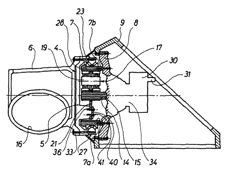
The wind turbine shown in Fig. 1 comprises a rotor l, a nacelle ? and a tower
3. As
illustrated in Figs. 2 and 3, the nacelle 2 comprises a planetary gear 4, and
the hub 6
of the rotor 1 is rigidly secured to the planetary holder 5 of said planetary
gear 4. The
planetary gear 4 is connected or connectable to the shaft of an electric
generator not
shown. The planetary gear 4 comprises a ring gear 7 provided with a toothing
7a on the
side turning radially inwards. The ring gear 7 is fixedly mounted on a housing
part 8,
which in turn is rigidly connected to an engine frame 9 in the nacelle. The
ring gear 7
can optionally be secured directly to the engine frame 9. The planetary gear 4
com-
prises planetary wheels 17 engaging a centrally arranged sun wheel 14 which
com-
CA 02442028 2003-09-24
prises a tubular extension 15. A parallel gear 30 can be inserted between the
tubular
extension and the generator shaft not shown, said parallel gear being
diagrammatically
indicated. The output shaft of the parallel gear is indicated at 31. The hub 6
comprises
three openings 16, only one opening being shown, and the blades of the rotor
ca.n be
5 secured in these openings. The planetary holder is rotatably mounted in the
ring gear
7 by means of the above planetary wheels. The planetary wheels are provided in
form
of at least two sets of planetary twin wheels, where one set of planetary twin
wheels
17 comprises the planetary wheels 17a and 17b. The second set of planetary
twin
wheels is identical with the first set of planetary twin wheels and does not
appear from
the Figure. Each set of planetary twin wheels 17 is mounted in a bogie on a
bogie shaft
19, which can be secured to a carrier plate 21 rigidly connected to the
planetary holder
5. The planetary holder is furthermore rotatably arranged on the curved outer
side 7b
of the ring gear 7 by means of an outer radial-axial-roller bearing 27. This
ra-
dial-axial-roller bearing 27 is mounted between the above outer side 7b and an
axially
rearward collar 23 on the planetary holder 5, said collar proj ecting r
adially beyond the
ring gear 7.
As illustr ated, each planetary wheel 17a or 17b of each set of planetary twin
wheels can
be mounted on the bogie shaft 19 by means of a double spherical roller bearing
25.
This r oiler bearing 25 is preferably a radial-axial-roller bearing, the
rollers 25' of which
can run on a common spherical traclc 25", cf. Fig. 3, on an outer race 25"' in
the bear-
ing. The above statements on the planetary wheel 17a also applies to the
planetary
wheel 17b and possible further planetary wheels in the planetary gear.
As shown, the radial-axial-roller bearing 27 of the planetary holder collar 23
can be
placed at a location on the outer surface 7a of the ring gear, said location
opposing the
bogies of the planetary holder 5, a bogie being formed by a bogie shaft with a
set of
planetary twin wheels.
The carrier plate 21 can be slightly resilient, and as shown the planetary
wheels 17a
CA 02442028 2003-09-24
6
and 17b of each bogie can be separated by means of the plate 21, said
planetary wheels
being arranged on their respective sides of said plate 21.
An auxiliary planetary gear 34 can be mounted behind and in connection with
the
planetary gear 4, the housing of said auxiliary planetary gear 34 being
indicated. This
auxiliary planetary gear serves to increase the r atio of the number of
revolutions of the
shaft of the elects is generator not shown to the number of revolutions of the
hub 6 of
the rotor .
The rotor hub 6 can be secured to the planetary holder 5 by being bolted onto
the collar
23 of the latter by means of a plurality of bolts 33 which also extend into an
outer race
27a in the outer radial-axial-roller bearing 27. The outer race 27a in this
bearing can
comprise a radially inward, circumferential projection 27a' with two
frustoconical
surfaces facing partially away from one another and forming the outer tracks
27a" for
the rollers 27a"' of the bearing, whereas an inner race 27b in said bearing
comprises a
corresponding circumferential depression with two frustoconical surfaces
partially
facing one another and also forming tracks 27b" for the bearing rollers 27a"'.
The planetary holder 5 can be substantially pot-shaped and be pr ovided with
at least
two inner axially directed projections Sb. The carrier plate 21 can be secured
on these
axially directed proj ection for instance by being squeezed in a track 36 in
the proj ection
by means of an end plate 40 screwed thereon by means of of bolts 41.
Should the wind turbine be subjected to particularly heavy wind forces while
in use,
the carrier plate 21 and the planetary twin wheels 17a and 17b can yield
slightly,
whereby said carrier plate can be slightly resiliently deformed and the
rollers 25' in the
bearings of the planetary wheels can move slightly on the spherical tracks 25"
as the
bogie shaft 19 is slightly turned. As a result, the forces transferred through
the plane-
tary wheels are pressure loads being uniformly distributed acs oss each tooth
at the
engaging locations.
CA 02442028 2003-09-24
The invention may be modified in many ways without thereby deviating from the
scope
of the invention.