Note: Descriptions are shown in the official language in which they were submitted.
CA 02442142 2003-09-23
WO 02/082666 PCT/IB02/02035
l
Transmissions ire. a commux~ication system
Field of the Invention
~T'he,.present invention relates to a communication system, and
in particular, but not exclusively, to transmissions between
stations of a communication system.
Background of the Invention
Various different communication systems adapted to provide
wireless communication between two or more stations are known.
IS Wireless communication media may be provided between a station
of a communication network and a user equipment. Wireless
communication media may also be provided between two user
equipment or between two stations of a communication network.
A wireless communication systems may be used for various tykes
of communication, such as for voice communication ar data
communication. A wireless system may provide circuit switched
or packet switched services or both. In packet switched
services data (e.g. speech data, user data, video data or
other data) is communicated in data packets. The development
in the wireless communication has lead to systems that are.
capable of transporting data in substantially high~data rates
i.e. the so called high speed data (HSD).
An example of wireless communication systems is a cellular
communication system. In a cellular system the user equipment
may access the communication network via access entities
referred to as cells, hence the name cellular system. The
CA 02442142 2003-09-23
WO 02/082666 PCT/IB02/02035
2
skilled person knows the basic operational principles and
elements of a cellular network and these are therefore not
explained herein in any greater detail. It is sufficient to
note that a cell can be defined as an radio access entity that
S is served by one or several base stations (BS) serving user
equipment (UE) via a wireless interface therebetween. Examples
of the cellular networks include networks that are based on
access systems such as the CDMA (Code Division Multiple
Access), WCDMA (Wide-band CDMA), TDMA (Time Division Multiple
Access), FDMA (Frequency Division Multiple Access), or SDMA
(Space Division Multiple Access) and hybrids thereof.
A wireless communication system is typically provided with a
radio resource management function. A feature of the radio
IS resource management is that it may continuously adjust the use
of resources such as the power levels between a base
(transceiver) station and user equipment associated with said
base station during communication between the base station and
the user equipment. Use of radio resources may be controlled
for transmissions that occur from the base station towards the
user equipment (downlink) and from the user equipment towards
the base station (uplink). The adjustment is done in order to
provide a sufficient quality and reliability for the
transmission between the base~station and the user equipment
in various conditions and, on the other hand, to reduce power
consumption and interference caused by the communication to
other devices.
A user equipment may communication simultaneously with a
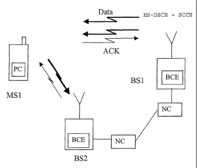
number of base stations. Figure 1 shows an example where a
user equipment MS1 is in communication with two base stations
BS1, BS2. The simultaneous communication with a plurality of
CA 02442142 2003-09-23
WO 02/082666 PCT/IB02/02035
3
base stations may occur, for example, when a user equipment is
to be handed over from a base station to another base station.
The handover may be performed by means of the so called soft
handover procedure. For example, in the CDMA soft handover may
be used to reduce the interference caused by the user
equipment. During a soft handover the transmission power of a
user equipment is typically adjusted based on power control
commands from a base station that request for the lowest
transmission power. Each base station involved in the soft
handover measures the quality of the signal from a given user
equipment and sends its power control commands to the user
equipment asking the power up or down. The user equipment
increases its transmission power only if all base stations
involved in the soft handover request for more power.
The user equipment may receive data such as control messages,
user data and so on from a base station. The user equipment
may receive data from more than one base station. Some of
these data transmissions may need to be responded by the user
equipment. The response may, for example, be an
acknowledgement that the user equipment did receive the
message and/or that the user equipment did accomplish a task
in response to the message and/or a response to an inquiry
and/or any other feedback that may be required by the base
station. The following will discuss a more detailed example
that relates to acknowledgements in a third generation
wideband code division multiple access (3G WCDMA) system.
In WCDMA. based systems the above referred high speed data may
be enabled e.g. by means of the so called high speed downlink
packet access (HSDPA) technology. The high speed downlink
packet access (HSDPA) may include functions such as fast
CA 02442142 2003-09-23
WO 02/082666 PCT/IB02/02035
4
hybrid automatic. repeat request (HARQ), adaptive coding and
modulation (AMC) and/or fast cell selection (FCS) . These
functions are known by the skilled person and will thus not be
explained in more detail: A more detailed description of these
and other function of the HSPDA can be found e.g. from a third
generation partnership project technical report No. 3G
TR25.848 release 2000 titled 'Physical Layer Aspects of UTRA
High Speed Downlink Packet Access'. It shall be appreciated
that although the HSDPA has been specified for use in the
WCDMA., similar basic principles may be applied to other access
techniques.
At the present it is assumed that in the high speed downlink
packet access (HSDPA) each user equipment receiving data on a
high speed downlink shared channel (HS-DSCH) also has an
associated dedicated channel (DCH) allocated. The dedicated
channel may be mapped to a dedicated physical channel (DPCH)
in the physical layer., The DPCH is typically divided into
dedicated physical data channel (DPDCH) and dedicated physical
control channel (DPCCH) both in the uplink andythe downlink.
Data such as they ower.-control commands, transport format
information, and dedicated pilot symbols are transmitted on
the DPCCH. Information such as diversity feedback information
may also be transmitted on DPCCH in the uplink. The HS-DSCH
may be mapped to one or several high speed physical downlink
shared channels (HS-PDSCH) in the physical layer.
The associated dedicated channel is typically provided both in
the downlink and the uplink. The dedicated channel is
typically used to carry HSDPA related information/signalling
as well as other dedicated data such as speech and control
data. The user equipment may communicate with several base
CA 02442142 2003-09-23
WO 02/082666 PCT/IB02/02035
stations at the same time. For example, the associated
dedicated channel may be in soft handover.
In addition to associated dedicated channels, the HS-DSCH may
5 be associated also with a shared control channel (SCCH). The
SCCH can be used to carry HS-DSCH specific
information/signalling to those users receiving data on the
HS-DSCH.
A current proposal is to use the dedicated channel to inform
the user equipment that it has data to be read on the HS-DSCH
and SCCH. That is, only those users receiving data at a given
time will receive an indication on the dedicated channel. The
dedicated channel may be called as a pointer channel since it
points to the shared channels. The dedicated channel may also
contain information about modulation and coding schemes, power
levels and similar parameters used for the shared channels.
This information can be sent also on the shared channel. The
shared control channel on the other hand is used to carry
information that is specific to the data transmitted on the
shared data channel (HS-DSCH). This information can contain
for instance packet numbers for the HARQ and so on. The shared
control channel can be sent on a separate code channel (code
multiplexed) or using the same code channels as HS-PDSCH (time
multiplexed).
Unlike the dedicated channel, the HS-DSCH is assumed not to be
in soft handover. That is, each base station is assumed to
have~their own shared channel and the user equipment is
assumed to receive data from only one base station at a time.
The so called fast cell selection (FCS) technique may be used
CA 02442142 2003-09-23
WO 02/082666 PCT/IB02/02035
6
to switch the data transmission from one base station to
another. However, the shared channels does not use power
control. Instead, the shared channels are proposed to be
transmitted with fixed or semi-fixed power. The term 'semi-
s fixed' means in here that the power is not changed often. The
power could, for instance, be a cell specific parameter.
In the currently proposed arrangements the high speed downlink
shared channel (HS-DSCH) is planned to be associated with a
dedicated channel which would carry in the downlink at least
information regarding the timing when the receiving station is
to receive on a shared channel. The associated dedicated
channel may possibly carry also other information. Tn the
uplink, the associated dedicated channel may carry, for
example, the required acknowledgements (ACK) for a fast HARQ.
The inventor has found that this may be problematic for
example in the context of the uplink power control of the fast
HARQ acknowledgements. A problematic situation may occur
especially when the associated dedicated channel is in the
soft handover mode. During the soft handover the uplink power
is adjusted in accordance with the best quality uplink among
an active set of base stations. However, signalling on the
high speed shared channel may be transmitted from another base
station. The communication link between the user equipment and
said other base station may be of poorer quality than said
best uplink connection. Nevertheless, said other base station
expects to receive responses such as an acknowledgement from
the user equipment. Since the quality of this uplink
connection. may be of substantially poorer quality than what
the best uplink is, there is a risk that the response is not
properly received and decoded or is not received at all.
CA 02442142 2003-09-23
WO 02/082666 PCT/IB02/02035
7
The fast cell selection function may be used to guarantee in
some occasions that best possible downlink is utilised for
communication towards the user equipment. However, the base
station that provides the best uplink may be different than
the base station providing the best downlink. This may be so,
for example due to fast fading or other changes in the
signalling conditions. This may increase the unreliability of
the responding functionality.
The prior art proposals for solving this problem include so
called strong coding, e.g., by using repetition coding. In the
repetition coding the acknowledgement (ACK) bit or bits is/are
repeated several times. This, however, may cause too much
additional load on the air interface and/or reserve too much
of the radio resources if one wants to guarantee the correct
reception of the acknowledgement message.
Another prior art proposal is the so called fixed power offset
for acknowledgement (ACK) transmissions. This means that all
acknowledgement messages are transmitted with increased or a
certain power in order to ensure that the acknowledgement is
- received even through the poorest quality uplink. However,
even a fixed power level for acknowledgement messages may not
completely solve the problem of substantially poor signalling
conditions. Thus situations where the power is not high enough
may still occur. ~n the other hand, it is also possible that
the fixed power level is unnecessarily high.. Thus, in addition
to reliability problems this approach may be disadvantageous
in that too high power is used by the user equipment causing
interference and unnecessarily high power consumption.
CA 02442142 2003-09-23
WO 02/082666 PCT/IB02/02035
8 ,
Summary of the Invention
Embodiments of the present invention aim to address one or
several of the above problems.
According to one aspect of the present invention, there is
provided~a method for communication between a first station
and a second station, comprising: communicating from the first
station to the second station information associated with the
manner how the second station should transmit towards the
first station; and transmitting from the second station based
on said information from said first station instead of
transmitting in a manner the second station would have
~_._._.. ~...
~"~,~,.~"~~.~"._.....,_,~,.~..,.__.......~...M_.._._..,..~.,.~_.,.._",..~M~.~.A
..~~~...~...w_..n..,.....
transmitted had it not been provided with said information.
......~,..._..~_...~.~,~...._u."~.,..~~......~a~~.~~.........~,~. .~.,~_....
V.,.x,~..f...~.~, ..,~.~.~.u~,.~M"....~. ~....."u..~.~"..~,~...,....
In a specific embodiment said information is transmitted on a
dedicated channel from the first station to the second
station.
In another specific embodiment said information is
communicated in a message that is transmitted from the first
station to a second station. A response to the message is then
transmitted from the second station based on said information.
The second station may transmit with a transmission power that
has been set based on said information after having received
the information.
The second station may repeat the transmission, the number of
transmissions depending on said information.
CA 02442142 2003-09-23
WO 02/082666 PCT/IB02/02035
9
Said information may define an offset parameter, the power
level of~the transmission being shifted an amount as indicated
by said offset parameter for the transmission.
rn an additional step the quality of the interface between the
first and second stations is determined. The information to be
transmitted to the sec~nd station is then defined by the first
station based on said determination.
The second station may be in communication with at least one
further station, said further station providing control
instructions to the second station. The second station may be
involved in a handover between said at least two stations. The
second station may be in a soft handover mode.
According to another aspect of the present invention there is
provided a communication system comprising: a station; a user
equipment for communication with the station via a wireless
interface, said user equipment being adapted to control at
2~ least one transmission parameter; and control means adapted
for provision said user equipment with information associated
with a transmission parameter for use by the user equipment
when transmitting to the station, the user equipment being
enabled to transmit with a different transmission parameter
based on said information than what the transmission parameter
would be if the user equipment had not been provided with said
information.
At least one further station may be provided, said further
station being adapted for communication with the user
equipment, the arrangement preferably being such that the user
equipment is adapted to follow control instructions from said
further station unless said information is provided thereto.
CA 02442142 2003-09-23
WO 02/082666 PCT/IB02/02035
According to another aspect of the present invention there is
provided a station for a communication system comprising
control means for generating a message to be communicated from
5 the station to another station, said control means being
adapted to provide said other station with information
associated with a parameter for use by said other station for
use in control of communication from said other station to the
station when responding the message.
According to another aspect of the present invention there is
provided a user equipment for communication with a station of
a communication system via a wireless interface, comprising
means for receiving a message from the station and control
means for transmitting a response to the message, wherein the
user equipment is adapted to transmit the response in
accordance with control information received with the message.
Brief Description of Drawings
For better understanding of the present invention, reference
will now be made by way of example to the accompanying
drawings in which:
Figure 1 shows an access system wherein the present
invention may be embodied;
Figure 2 is a flowchart illustrating the operation of an
embodiment of the present invention; and
Figure 3 shows a specific embodiment.
30' Description of Preferred Embodiments of the Invention
An embodiment will now be described with reference tb a mobile
telecommunication system. The exemplifying communication
CA 02442142 2003-09-23
WO 02/082666 PCT/IB02/02035
l1
system comprises a radio access part adapted to operate based
on the WCDMA (Wideband Code Division Multiple Access)
technique. A feature of the WCDMA based systems is that a
plurality of user equipment is allowed to communicate with a
base transceiver station in a cell over a radio interface
(only one user equipment, however, is shown in Figure 1 for
clarity). As shown by Figure l, a user equipment is also
allowed to be in radio communication with more than one base
station at the same time. Figure 1 shows only two base
stations BSl, BS2 for clarity.
The user equipment comprises a mobile station MS1. The term
mobile station refers to a mobile user equipment that is
enabled to move from a location to another. A mobile station
may also roam from one network to another network, if the
other network is compatible with the standard the given mobile
station is adapted to and there is a roaming agreement between
the operators of the two networks.
Each of the base stations BSI, BS2 may be provided with a
controller entity BCE. The controller entity may be adapted to
perform various task, such as to measure and control power
levels that are used for communication between the base
station and the mobile station MSl. In addition to the
controller entity of the base station, the operation of the
base station may also be controlled by, at least one further
controller entity, such as a radio network controller NC. The
arrangement is typically such the various control functions
associated with a base station are divided between the
controller entity of the base station and a network controller
entity. A network controller entity may be adapted to control
one or several base stations.. The various network controller
CA 02442142 2003-09-23
WO 02/082666 PCT/IB02/02035
12
entities may be connected to each other for communication
therebetween.
Communication between the mobile station and the base stations
S may comprise any kind of data such as speech data, video data
or other data. The base stations and mobile station
communicate also control data. The control data may associate
with management operations. The control data may comprise
messages such as various request and acknowledgements.
Data may be transmitted between the stations as a plurality of
data symbols in subsequent data or radio frames. The signals
carrying the data may be transmitted with variable data symbol
transmission rates (data speeds), wherein the~transmission
rate may be different in subsequent frames of the
transmission. The data symbols may be transmitted based on
different access techniques. For example, in the CDMA (Code
Division Multiple Access) system data is encoded for
transmission by processing data symbols to be transmitted by a
spreading code for each transmission channel. In the TDMA
(Time Division Multiple Access) system data is transmitted in
different time slots allocated for different channels.
The communication between the mobile station MSl and the base
stations BS1 and BS2 may occur via different communication
channels, such as via a dedicated channel, shared channel and
so on. In some systems such as the CDMA the channels may be ,
distinguished from one another by the use of scrambling codes
in a manner which is known by the skilled person.
In Figure 1 the different signalling conditions between the
mobile station and the base stations are illustrated by
different widths of the arrows between the stations. As shown,
CA 02442142 2003-09-23
WO 02/082666 PCT/IB02/02035
13
base station BS1 has a weaker uplink with the mobile station
MS1 than the other base station BS2. This implies that the
power control of the uplink follows the base station BS2.
However, as shown in Figure 1, the downlink from base station
BS1 may be stronger than what the downlink from the base
station BS2 is.
Each of the base stations of Figure 1 may be enabled to
measure one or more parameter that associate with the
connection. The parameter may be a quality parameter such as
the power levels or signal to interference (SIR) level in the
uplink. That is, the power level or SIR level at which each
base station BS1, BS2 receives from the mobile station MS1 may
be known by the respective base station.
The power control mechanism in the access network is typically
such that the mobile station MS1 follows the power commands
received from the "strongest" base station, e.g. the base
station BS2 that receives the signal transmitted by M51 with
the best quality parameter._The transmission power of the
mobile station MS1 is then adjusted accordingly even if the
other base station BSl keeps on asking for more transmission
power. This is so since the mobile station MS1 only increases
transmission power if all those base stations that are in soft
handover with the mobile station MS1 ask for more power.
Tn the following example it is assumed that in normal
operation the mobile station MS1 adjusts it transmission power
based on the power commands received from the base station
B52. The power adjustment mechanism may be based on use of the
so called quality target or power threshold values. If the
quality of the connection is below the target value, the
mobile station MS1 is asked to increase the transmission power
CA 02442142 2003-09-23
WO 02/082666 PCT/IB02/02035
14
and if the quality is above the target, the power is asked to
be decreased.
The connection quality target can be announced e.g. by means
of so called Eb%No (Signal Energy/Noise) or SIR (Signal to
Interference Ratio) or desired signal level target or a
similar parameter indicating a quality measure which can be
estimated for the connection between two stations.
The quality of the connection is controlled based on the
target value. Any of the connection parameters that have
influence to the quality of the connection should follow any
changes in the target. In most cases it is sufficient if the
transmission power is increased/decreased in order to meet the
quality target value. A more detailed description of a
possible closed loop power control mechanism can be found, for
example, from 3GPP (third generation partnership project)
technical specification No. TS25..214 "Physical layer
procedures (FDD') " .
2O
In addition to the closed loop power control mechanism the
CDMA systems may include also an outer loop power control
mechanism. This may adjust the power or SIR target based on
other quality target parameters such as the bit error rate
(BER) or frame error rate (FER) or any other similar quality
target the connection should meet.
In. the embodiments a first station may transmit data or a
request or an enquiry to a second station. After reception of
said transmission the second station then transmits a response
back to the first station. To improve the reliability and/or
optimise the use of resources, information associated with at
least one parameter for the response is signalled from the
CA 02442142 2003-09-23
WO 02/082666 PCT/IB02/02035
first station to the second station. This parameter may, for
example, associate with the required power levels of the
response and/or the number of times the response shall be
transmitted and so on, The response signalling is then
5 performed based on the received information.
In the Figure 1 example the first station is the base station
BSI and the second station is the mobile station MSl. For
example, when the base station BS1 allocates a channel to the
10 mobile station MS1 and sends data thereto on the high speed
data shared channel (HS-DSCH), the base station BS1 expects
the mobile station to return an acknowledgement (ACK).
The base station BS1 may provide the mobile station with
15 information on an associated control channel (either dedicated
or shared) regarding the power levels required for the
response. In a preferred embodiment the information provides
the mobile station MSl with. an offset value. The offset value
indicates the difference in power relative to power level used
for transmission in the best uplink with the base station BS2.
The base station BS1 determines the offset that is needed for
the reliable acknowledgement transmission from the mobile
station MS1 based on one or more measurements associated with
transmissions from the mobile station. The power is determined
such that a predefined level of reliability is obtained for
the decoding of the acknowledgement at the base station BS1.
The mobile station MS1 is provided with appropriate power
control entity PG. A per se known power control entity can be
adapted to incorporate a feature that enables adjustment of
the response transmission power levels based on the
information received from the base station BS1. That is, the
power control entity of the mobile station may make a decision
CA 02442142 2003-09-23
WO 02/082666 PCT/IB02/02035
16
that the response transmission needs to be accomplished in a
different power level than what is used for communication with
the best base station BS2 and control the transmission
accordingly.
The acknowledgement message (ACK) may be transmitted back to
the base station BS1 on a dedicated channel. The dedicated
channel may be 'on' all the time even if there is no
acknowledgements to be sent. This is so in order to keep the
closed loop power control running. The active base station BS1
may measure a quality parameter such as the signal to
interference ratio (SIR) of this dedicated channel for overall
power control purposes. This may be done e-.g. based on so
called pilot bits that are transmitted by the mobile station.
Thus the base station BS1 can calculate a required power
offset. The power offset requirement is signalled from the
base station BS1 to the mobile station MS1 with the downlink
data packet to tell the mobile MS1 how much more power is
required for the acknowledgement transmission.
New signalling bits may be added in the downlink transmission
from the base station BS1 to tell the required power offset
for the user equipment MS1. These bits may be sent, e.g., on
the shared control channel since only the user equipment or
those user equipment receiving on the downlink shared data
channel need to send the acknowledgement ACK. That is, this
information is not needed all the time, but~only when there is
data packets to acknowledge. Alternatively, the base station
may sent these bits to the user equipment via a dedicated
control channel or dedicated data channel.
The power control may be accomplished in a slot by slot basis
in access techniques wherein the transmissions occur in slots.
CA 02442142 2003-09-23
WO 02/082666 PCT/IB02/02035
17
A transmission can be divided into the slots e.g. based on
time or by means of a spreading code. The mobile station MS1
may be adapted to assign power far the slots in accordance
with a "normal" power control mechanism unless the mobile
station has been provided with information which requires use
of a different power level for a slot (or several slots) that
are allocated for the response.
In a simple case one bit may be enough for the provision of
the above referenced information. For example, '0' could
indicate that an offset of 5dB is required and '1' could
indicate an offset of lOdB. According to another possibility
'0' could indicate that no offset is required and '1' could
indicate that a predefined additional power is required.
IS
2 to 4 bits may be used in a typical application for defining
4 to 16 different power offset levels. A step between the
different power levels may be, for example, 2, S or 10 dB.
Alternatively the step size between the power levels may be
adapted to change nonlinearly.
A more specific embodiment will now be described with
reference to Figure 3 showing transmission of data packets
between a base station (node B) and two user equipment UE1 and
UE2. It shall be appreciated that although Figure 3 shows
channels in association with only one base station, a
plurality of base stations may have communication channels
with the user equipment UE1 and/or UE2 at the same time. Other
channels are, however, not shown for reasons of clarity.
A number of packets is shown to be transmitted to a first user
equipment UE1 and to a second user equipment UE2 on the data
channel HSPDSCH. The vertical lines of Figure 3 dividing the
CA 02442142 2003-09-23
WO 02/082666 PCT/IB02/02035
1B
transmission into sections indicate a high speed downlink
packet access transmission time intervals (HSDPA TTI). The
HSDPA TTI is a collection of a defined number of slots. That
is, the high speed downlink packet access transmission time
interval (TTI) defines a period for data transportation
between user equipment and a base station via the high speed
downlink shared channel (HSDSCH). Logically the TTI can thus
be seen to correspond the concept of data frames. In the
Figure 3 example eight TTIs are shown, each TTI being three
slots in length.
In the following it is assumed that the acknowledgements are
provided in accordance with the fast hybrid automatic repeat
request (HARQ) scheme. A so called N-channel HARQ is also
assumed to be used for the fast HARQ together with a so called
stop-and-wait protocol. The stop-and-wait protocol may be used
in order to reduce buffering requirements of the receiving
station.
The N-channel HARQ supports asynchronous transmission. Thus
different users can be scheduled freely without need to wait
for completion of a given transmission. The receiving station
may need, however, to know to which HARQ process the packet
belongs to. This information can be explicitly signalled on a
high speed downlink packet access (HSDPA) control channel
(CH), e.g. the SCCH. For example, after three packets have
been transported to the first user equipment UE1, two packets
may be transmitted to the second user equipment UE2. The
transmission to the first user equipment UE1 may in such case
be delayed by two TTIs. The processing times of data packet to
different user equipment should be defined such that
continuous transmission to a.user equipment is possible.
CA 02442142 2003-09-23
WO 02/082666 PCT/IB02/02035
19
Each packet is preferably acknowledged during the transmission
of other packets so that the downlink (DL) channel can be kept
occupied all the time when there are packets to be
transmitted.
In Figure 3 the uplink acknowledgements are shown to be
transmitted on the dedicated physical control channel (DPCCH).
Arrows R1 to R9 indicate various relations between different
operations. That is, relations between pointer bits on the DL
DPCH, shared data and control channel (HS-PDSCH and SCCH)
transmission and the acknowledgement transmissions.
More particularly, each of the double lined arrows R2, R5 and
R9 indicates a quality measurement performed for the uplink of
a given user equipment on the respective dedicated control
channel. The single lined arrows Rl, R4 axid R8 indicate the
relationships between the pointer bits and shared control
channel SCCH in the downlink. The single lined arrows R3 and
R6 indicate the relationships between the downlink data
channel HSPDSCH and acknowledgements in the uplink. The
acknowledgements are transmitted with a power that has been
adjusted based on information received on the SCCH, that is
based .on the results~of the measurements.
During the first interval TTI1 the base station transmits a
pointer bit to the user equipment UE1. The pointer b.it
indicates that the user equipment UE1 shall receive data and
control information during the next TTI (TTI2) on the HS-PDSCH
and on the SCCH. Also during TTI1, the base station measures
the quality of the uplink of the user equipment UE1. These
CA 02442142 2003-09-23
WO 02/082666 PCT/IB02/02035
relations are shown by the relation arrows R1 and R2,
respectively.
For example, the SIR of the uplink can be measured from the
S dedicated pilot symbols transmitted on the DPCCH in every
slot. Based on this quality measurement, the base station ,
provides the user equipment UE1 in the TTI2 with information
regarding the power level that should be used when
transmitting the acknowledgement during TTI4. This relation is
10 indicated by arrow R3. The power level information can be
provided as a power offset, as explained above. This power
offset information may be, for example, provided as a field of
a few bits in the shared control channel (SCCH).
ZS Tt should be noted that the measurements may be averaged over
a longer period of time or otherwise processed. The arrow R2
simply shows that the power offset used for the transmission
is based on the measurements) done before the transmission of
the power offset.
After having received the power level information the user
equipment UE1 sends the acknowledgement using a power level
that is based on information from the base station. The
acknowledgement may be a positive acknowledgement (A in Figure
3) or a negative acknowledgement (N in Figure 3).
In Figure 3, some of the acknowledgement slots are shown to be
higher in order to illustrate that increased transmit power is
used for these acknowledgements. The increased power may be
applied for the whole slot or only on the acknowledgement bits
within the slot. The same increased power may also be used in
CA 02442142 2003-09-23
WO 02/082666 PCT/IB02/02035
21
other slots if they contain other information such as
measurement or quality report which is sent only to the same
base station as the acknowledgement. The increased power may
also be applied to the entire TTI or even a number of TTIs.
In addition to relations R1 to R3, Figure 3 illustrates also a
second set of relations R4 to R9 that associate with the user
equipment UE2. In this case the acknowledgement was negative
(N) and therefore a new pointer bit was given on the DL CPCH
channel of the second user equipment UE2 for retransmission of
the message.
In order to ensure that the power level for the response can
be determined appropriately by the base station the uplink
quality measurement is preferably accomplished as late as
possible. As shown, information associated e.g. with the
measurement as indicated by the arrow R2 is transmitted in the
next transmission time interval (TTI2) on the control channel
(DLSCCH) .
The embodiments are especially suitable for acknowledgements
because the acknowledgements need to be sent in response to a
downlink transmission and also because the reliability of the
acknowledgement transmission should be high.
The message specific control information may be signalled only
when the first station determines that a different parameter
is needed in order to ensure a reliable response by the user
equipment.
Figure 4 shows a further embodiment in which the user
equipment first follows power commands from the strongest
CA 02442142 2003-09-23
WO 02/082666 PCT/IB02/02035
22
base station, that is from a base station BS2. Another base
station BSl sends a 'power offsetl' message to the user
equipment. After having received the 'power offsetl' message
the power control function of the user equipment starts to
S follow said other base station.
The user equipment power control may set its transmission
power based on the message from the base station BS1 for a
predetermined time. The user equipment may alternatively
follow the commands from the base station BS1 as long as it
has some information, such as acknowledgements or measurement
reports or so on to be sent to this base station. The user
equipment may also wait for new power offset information from
any of the base stations it is in connection with. That is, a
new offset such as the shown 'Offset2' will replace the
previous offset parameter.
When the user equipment power control returns to the "normal"
soft handover mode the user equipment may change (typically
decrease) its power back to the level it used before :receiving
the offset command 'Ofsetl'. That is, the user equipment may
start to follow the power control commands from the strongest
base station BS2 having the best uplink with the user
equipment. This may be accomplished by using offset parameter
that equal with the first offset (i.e. offset2=offsetl in,
Figure 4) informed by the base station BS1 or a predetermined
second offset (offset2). The second offset may be a function
of the said first offset. The second offset may also be
informed by the base station BS2 having the best uplink.
.
In a further embodiment each base station in connection (for
instance, in a soft handover) with the user equipment may
continuously measure the quality of the uplink. In addition to
CA 02442142 2003-09-23
WO 02/082666 PCT/IB02/02035
23
or instead of the normal power control commands each of the
base stations may send power offset information to the user
equipment telling how much the power should be changed
(increased or decreased) in order to meet the quality target.
This information is preferably sent on the dedicated control
channel. In a normal soft handover case the user equipment may
then use the offset that results in the lowest transmission
power or alternatively follow the normal power control
commands. However, when the user equipment has something to
send to one base station only, the user equipment may then use
the power offset sent by that base station. The offset may be
sent periodically, e.g., in each slot as the power control
commands, or once per every n slots and so on. The offset
information may also be sent when needed, e.g., when the value
of the offset exceeds some threshold values.
In an embodiment the user equipment may also be forced to use
stronger coding for the transmission of the acknowledgement
message. For example, the user equipment may be instructed to
transmit the acknowledgement repeatedly. For example, instead
of sending the acknowledgement once the user equipment may be
instructed to transmit the acknowledgement three, five, or ten
times and so on. According to an embodiment the user equipment
is instructed to transmit the acknowledgement e.g. in three
slots instead of one slot so that the acknowledgement can be
decoded reliably.
The above~discussed transmission parameter information
provision mechanism may also be used in connection with other
signalling functions than acknowledgements. The response
messages could be, for example, measurement reports or other
reports. The herein proposed signalling mechanism may be
especially advantageous if a report is requested by a base
CA 02442142 2003-09-23
WO 02/082666 PCT/IB02/02035
24
station of a plurality of base stations in communication with
a user equipment. The base station may inform the user
equipment of the power offset and/or any other parameter that
is to be used for the response towards the specific base
station.
The above discussed adjustment of at least one feature of the
response signalling based on information from power level
measurements. The adjustment may also be based on other
information that associates with the interface between the two
stations. For example, the base station BS1 may request for a
certain power offset based on analysis of the previous '
responses from the mobile station MS1. If the analysis
indicates that a certain number of responses has not been
correct, the offset may be increased in order to improve the
reliability. The responses may be earlier ACKs or other data
transmitted from the user equipment, e.g., speech packets.
It is noted that the above disclosed solution is applicable
also in instances where the first message is sent from the
user equipment to a base station. In such a case the user
equipment may inform the base station of any requirements that
it may have for the response from the base station.
It shall be appreciated that whilst embodiments of the present
invention have been described in relation to mobile stations,
embodiments of the present invention are applicable to any
other suitable type of user equipment.
It shall be appreciated that whilst embodiments of the present
invention have been. described in relation to a mobile station
that is in communication with more than one base station, the
present invention is applicable also to instances where only
CA 02442142 2003-09-23
WO 02/082666 PCT/IB02/02035
two station are in communication with each other. For example,
a first station transmitting a message that is to be responded
by a second station may insert in the message information
regarding e.g. coding and/or power that is to be used for
5 responding to the particular packet.
It shall be appreciated that while this specification mentions
some system specific examples of the communication channels
the embodiments of the invention are not restricted by these
10 examples.
The response may also be sent, for example, on a shared
control channel or a data channel in systems where such a
channel is defined. A specific acknowledgement channel may
15 also be defined.
The data is described as being in packet form. In alternative
embodiments of the invention the data may be sent in any
suitable format.
25
In addition, it is not always necessary to measure the quality
of the connection for each data packet and/or to provide the
user equipment with the offset information each time a
response is required. Instead; the measurement may be
accomplished and/or information transmitted e.g. in predefined
intervals or in response to a predefined event. (e.g. the
quality of the connection has changed or the user equipment
has been relocated from a network controller to another
network controller and so on). It may thus be enough if the
offset information is provided once for the user equipment
during a connection between the user equipment and a base
station.
CA 02442142 2003-09-23
WO 02/082666 PCT/IB02/02035
26
The embodiment of the present invention has been described in
the context of a CDMA system.. This invention is also
applicable to any other access techniques including time
division multiple access, frequency division multiple access
or space division multiple access as well as any hybrids
thereof.
It shall be appreciated that the base station may in some
communication standards, such as those associated with the 3=a
generation (3G) universal mobile telecommunications system
(UMTS), be referred to as node B. However, this specification
has used the term base station for clarity.
According to an alternative solution for the above discussed
problem a dedicated physical channel (DPCH) is used only in
association with a high speed downlink shared channel (HS-
DSCH). That is, no other data is transmitted on the DPDCH. The
power control of the DPCH may then follow base station that
transmits on the active HS-DSCH (both in the uplink and the
downlink) instead of the best base station. If no other data
is transported on the uplink DPDCH, then the uplink power
control function of the mobile station could follow the active
high speed data base station. In such a situation information
regarding the power offset may not be needed for the uplink,
since the power control function may adjust the power.
It is also noted herein that while the above describes
exemplifying embodiments of the invention, there are several
variations and modifications which may be made to the
disclosed solution without departing from the scope of the
present invention as defined in the appended claims.