Note: Descriptions are shown in the official language in which they were submitted.
CA 02442143 2003-09-23
WO 02/097341 PCT/USO1/25900
CONVERSION OF SOLAR ENERGY
Technical Field
The present invention relates generally to conversion of sunlight into other
forms of
energy, including thermal energy and electrical energy, and, more
particularly, to use of elongated
concave trough-shaped reflectors connected in an array for unitary movement,
and maintaining
essentially perpendicularity between the reflectors and the rays of the sun to
heat water with
linearly-focused, reflected sunlight and to create electricity with point-
focused reflected sunlight
derived from the line-focused reflected sunlight.
Background Art
Solar energy is freely and daily available. It is a clean, non-polluting
source of energy.
Providing a reliable, long term, cost effective, efficient way of using
sunlight to obtain electrical
and thermal power has long been an unsolved problem, until the present
invention.
It has been proposed that flat panel solar converters be used to convert
direct sunlight into
thermal or electrical energy.
Pedestal supported flat panels using direct sunlight to generate electricity
were part of
the Solar One project.
A circular, but concave reflector mounted on a single column or pedestal has
been
proposed. This approach was used on the Soleras water desalination proj ect in
Saudi Arabia and
on the Solar Two project in Dagget, California.
Fixed position concave reflectors placed in an array and positioned in side by
side rows
on an incline have ben proposed. See U.S. Patent No. 4,202,322. Such an
installation was made
at the Federal Correctional Institution at Phoenix, Arizona.
CA 02442143 2003-09-23
WO 02/097341 PCT/USO1/25900
Tiltable elongated concave reflector assemblies have been utilized, such as
the one at
Barstow, California, owned by FPL Energy SEGS VIII and IX.
Solar Systems comprising bidirectionally controlled Fresnel lens and solar
cell
assemblies, utilizing direct sunlight, have been proposed. See, U.S. Patent
No. 4,649,899, for
example. Also see, U.S. Patent No. 4,245,153. Optical detectors for dual axis
tracking of the
sun are known.
The above-identified proposals and installations have failed to provide
reliable, low cost,
efficient, variable capacity systems by which solar energy is converted to
thermal and/or
electrical energy. A long felt need has existed for energy conversion plants
which are reliable,
efficient, cost effective and size variable to meet both low and high capacity
demands for thermal
and electrical energy.
Disclosure of the Invention
In brief summary, the present invention overcomes or substantially alleviates
the long
term problems of the prior art by which solar energy is converted to thermal
energy and/or
electrical energy. The present invention provides reliable, cost effective
systems for such
conversion, where the size of the system can be correlated to the desired
capacity.
The orientation of an array of elongated concave parabolic trough-shaped
reflectors is
biaxially kept essentially perpendicular to rays of the sun by a control such
that the sunlight is
reflected and concentrated along a focal line of each elongated reflector by
which (a) tube-
contained water is heated at the focal line by reflected sunlight impinged
thereon and/or (b) line
focused reflected sunlight is optically transformed into point focused
reflected sunlight from
which electricity is generated using solar cells upon which the point focused
reflected sunlight
is impinged.
2
CA 02442143 2003-09-23
WO 02/097341 PCT/USO1/25900
With the foregoing in mind, it is a primary obj ect of the present invention
to overcome
or substantially alleviate the long term problems of the prior art by which
solar energy is
converted to thermal energy and/or electrical energy.
Another paramount object of the present invention is to provide reliable, cost
effective
systems for such conversion, where the size of any such system can be
correlated to the desired
capacity.
A further obj ect of great significance is the provision of solar energy
conversion systems
wherein the orientation of an array of elongated concave parabolic trough-
shaped reflectors is
biaxially kept essentially perpendicular to rays of the sun by a control such
that the sunlight is
reflected and concentrated along a focal line of each elongated reflector by
which (a) tube-
contained water is heated at the focal line by reflected sunlight impinged
thereon and/or (b) line
focused reflected sunlight is optically transformed into point focused
reflected sunlight from
which electricity is generated using solar cells upon which the point focused
reflected sunlight
is impinged.
These and other objects and features of the present invention will be apparent
from the
detailed description taken with reference to the accompanying drawings.
Brief Description of the Drawings
Figure 1 is a perspective representation, schematic in nature of one
configuration
embodying principles of the present invention;
Figure 2 is a perspective of one form of the stationary lower frame forming a
part of
embodiments of the present invention;
Figure 3 is a perspective representation of an upper frame embodiment which is
rotated
optically to follow the sun, and reflector frames, the tilt of which is
adjustable in unison;
3
CA 02442143 2003-09-23
WO 02/097341 PCT/USO1/25900
Figure 4 is a diagrammatic representation of the manner in which the attitude
and
azimuth of the array of parabolic trough-shaped reflectors is displaced to
maintain
perpendicularity with the sun and the manner in which line-focused reflected
sunlight is
impinged upon a solar-to-thermal or solar-to-electricity converter;
Figure 5 is an enlarged fragmentary perspective of two parabolic trough-shaped
reflectors
and reflector frames together with energy converters disposed at the line
focal point of each
reflector, each converter being supported by two cantilevered structural
members;
Figure 6 is a fragmentary enlarged perspective of an optical detector used to
cause the
upper frame, reflector frames and reflectors to follow the sun in the sky so
as to preserve
perpendicularity between the reflectors and the rays of the sun;
Figure 7 is a schematic representation of a system by which line-focused
reflected
sunlight is converted to thermal energy;
Figure 8 is a diagrammatic representation of the manner in which point-focused
reflected
sunlight is converted to electrical energy;
Figure 9 is an elevational view, shown partly in cross section, illustrated in
the manner
in which the tilt of the array of reflectors is altered to maintain
perpendicularity with the sun;
Figure 10 is a fragmentary perspective illustrating, in part, the toggle
mechanism by
which the tilt of the array of reflectors is changed to maintain
perpendicularity with the rays of
the sun;
Figure 11 is an enlarged fragmentary representation of the toggle mechanism
illustrated
in Figure 10 viewing the same from the concave side of the reflectors as
opposed to the convex
side;
Figure 12 is an enlarged fragmentary perspective similar to Figure 11 further
illustrating
the manner in which a screw drive is motor displaced responsive to optical
signals to change the
tilt of the array of reflectors to maintain the above-mentioned
perpendicularity;
4
CA 02442143 2003-09-23
WO 02/097341 PCT/USO1/25900
Figure 13 is an enlarged perspective illustrating the manner in which the
upper frame is
displaced along a track of the lower to maintain said perpendicularity;
Figure 14 is cross section taken along lines 14-14 of Figure 13;
Figure 15 is a cross section taken along lines 15-15 of Figure 13;
Figure 16 is a fragmentary enlarged perspective representation illustrating a
portion of
the upper, displaceable frame, the motor and differential by which the upper
frame is rotated
selectively upon the lower frame;
Figure 17 is a fragmentary enlarged perspective illustrating the motor and
rotational drive
system by which the upper frame is rotated selectively upon the lower frame;
Figure 18 is likewise an enlarged fragmentary perspective of the rotational
drive system
by which the upper frame is rotated selectively in respect to the lower frame
for preserving
perpendicularity with the sun;
Figure 19 is a cross sectional view taken along line 19-19 of Figure 2;
Figure 20 is a fragmentary elevational view of an additional form of the
present invention
comprising a lower static frame supported upon columns and comprising a curved
track upon
which an upper frame is mounted for selective rotational displacement;
Figure 21 is a fragmentary plan view of a relatively large embodiment of the
present
invention wherein the upper frame is rotatably mounted upon two or more
tracks;
Figure 22 is a plan view of a torque tube drive which may be used in lieu of a
toggle
mechanism when a large array of parabolic reflectors is utilized;
Figure 23 is a cross section taken along lines 23-23 of Figure 22;
Figures 24 and 25 are cross sectional views illustrating the manner in which a
thermal
converter disposed at the focal line of a parabolic reflector may be
insulated;
Figure 26 is a perspective representation of an energy converter adapted to be
disposed
at the focal line of a trough-shaped parabolic reflector to convert solar
energy to electrical energy;
CA 02442143 2003-09-23
WO 02/097341 PCT/USO1/25900
Figure 27 is a plan view illustrating a different form of secondary reflector
to ensure point
focus impingement of reflected sunlight upon solar cells;
Figure 28 is a cross sectional view taken along line 28-28 of Figure 27;
Figure 29 is a fragmentary perspective of another reflector embodiment with
the support
frame on the convex or back side of the reflector; and
Figures 30, 31 and 32 are a cross section taken along lines 30-30, 31-31 and
32-32,
respectively, of Figure 29.
Best Mock for Carrying Out the Invention
The present invention utilizes the free and limitless energy of the sun to
produce
electricity and thermal energy. The scale of embodiments according to the
present invention can
be tailored to the need, ranging from small stand alone systems for
residential and small business
use to intermediate sized plants for plant or factory use to massive
assemblies design to mitigate
against if not eliminate the electrical energy crisis in California. The
present photovoltaic
invention is economical to install and maintain, is reliable and not
maintenance-intensive, is
efficient and cost effective to operate and does not pollute the environment.
The sun is not a
consumable resource.
Using the present invention, businesses, industrial plants, retail and office
buildings,
homes, farms and villages can produce some, ifnot all, of their own electrical
and thermal power,
and avoid the largest uncontrollable cost of doing business today - the ever-
escalating price of
purchased power generated from fossil and nuclear fuels.
This invention is capable of making significantly more energy per square foot
than
conventional flat plate solar collectors. And flat plate collectors are
incapable of co-generating
the large amounts of thermal energy that the present concentrating
photovoltaic generating
systems make automatically.
6
CA 02442143 2003-09-23
WO 02/097341 PCT/USO1/25900
Until now, remote installations have been faced with a cliff cult choice: pay
the
prohibitive costs of bringing in utility power, or depend on costly, noisy,
and hard to maintain
pollution-creating diesel, gas or propane generators. The present invention is
a third and better
choice, which can be scaled or sized to produce as much electrical and/or
thermal energy as
needed, independently, on site; the energy needed to power a home or business,
pump water,
irrigate land and run remote communication installations.
Unlike centralized forms of power generation, on-site de-centralized use of
solar power
needs no far-flung distribution network of gigantic towers and high voltage
lines. Instead it
utilizes a universally available asset - sunshine. No moving parts, except for
the perpendicularity
biaxial tracking system. It is noiseless, pollution-free, and requires almost
no maintenance over
many years of service.
Decentralized sunlight-derived electrical power can free users from the
effects of peak-
hour brown-outs, and from the possibility of total black-outs caused by
operator error or the
planned actions of groups hostile to utilities or nations.
The cost of the generating equipment itself - through the production of power
for a
building can be amortized over the life of the building, as part of debt
financing (mortgage).
Amazing as it may seem, one of the largest and most uncontrollable costs a
building owner faces
is the ever-escalating cost of power. Using the present invention, one
actually has the ability to
eliminate most of the cost of purchased power now and for years to come.
When land and water were plentiful and labor was cheap, little was known about
the
delicate balance existing between the environment and the extraction, burning,
and wastes of
non-renewable fuels. Now it is all too apparent that our supply of fossil
fuels is limited - and
that these sources are causing damage to our atmosphere, water supplies, and
food chain -
damage that is or may soon become irreversible. The costs, too, for fossil
fuels continue upward
7
CA 02442143 2003-09-23
WO 02/097341 PCT/USO1/25900
as the more accessible fuel deposits are consumed, and as the costs for
machinery, labor, and
transportation continue to rise around the world.
Ironically, the best answer to the world's need for energy has always been the
sun. The
sun can satisfy a significant percentage of our energy requirements while
helping us to become
independent of the negative aspects inherent in conventional power generation.
Switching to
solar-derived power will reduce the pollution produced by coal, oil and
nuclear fuels. It will also
slow the use of oil and allow us to conserve it for more valuable uses, such
as chemical
feedstocks and plastics. The rate of coal usage would also be slowed.
Harnessing the sun will
also reduce, or eliminate, the need for nuclear power and mitigate its many
risks and problems.
Even though the sun is just beginning to contribute to satisfying the world's
energy
demands on a large scale, direct sunlight has been powering satellites and
spacecraft since 1958.
In the 1970's the first terrestrially-directed sunlight photovoltaics supplied
power to locations too
remote to have ties to utility lines. Then, as the solar industry developed
more efficient silicon
cells and generators, larger grid-connected direct sunlight installations
became practical.
The present invention is not space-intensive. One embodiment of the present
invention
can be mounted on an existing rooftop so that it essentially takes up no
additional space at all.
Ground-mounted systems on a pad or the like is also an option as well. Column
mounting is a
further option.
Various embodiments of the present invention may be used in conjunction with
residences, office buildings, manufacturing facilities, apartment buildings,
schools, hospitals,
remote communications, telemetry facilities, offshore platforms, water pumping
stations,
desalination systems, disinfection systems, wilderness camping, headquarters
installations,
remote medical facilities, refrigeration systems, farms and dairies, remote
villages, weather
stations, and air conditioning systems, to name a few.
8
CA 02442143 2003-09-23
WO 02/097341 PCT/USO1/25900
The present invention is also useful in: (a) providing cathodic protection
against galvanite
corrosion, (b) storage of electrical energy in batteries and (c) generation
and sale of electricity
to utility companies.
The sun is an energy source that, unlike fossil fuels, is free each day to
whatever
generation site is selected. It does not need to be mined, transported,
refined, burned or
purchased. So the costs for all these steps to produce energy are eliminated.
Gone, too, are all
forms of pollution. There are no particulates or gases vented into the
atmosphere. Nor is there
a need for millions of gallons of cooling water. (The small amount of water
used to cool the
solar cells actually becomes a second form of co-generated power, i.e.
production of thermal
energy, that has dozens of residential and commercial uses.) So water is
conserved. There are
no massive discharges of hot water into coastal waters to elevate the normal
temperature and alter
and perhaps destroy the habitats and food chains of coastal marine life. With
solar energy, there
are no wastes of any kind to be removed or buried in mines or deep at sea, so
there are few, if
any, health risks to our generation or future generations.
Various embodiments of the invention are modular, allowing any installation to
be as
large or as small to meet exactly the needs ofthe installation for electrical
and/or thermal energy.
The electricity produced is direct current (DC), which, when appropriate, may
be transformed
into alternating current (AC) using an inverter or DC-to-AC converter.
At the heart of the present invention is the utilization of a system which
biaxially tracks
the location of the sun in the sky to maintain a perpendicularity between an
array of parabolic
trough-shaped reflectors and the rays of the sun so that reflected line or
point focused sunlight
may be efficiently converted into thermal and/or electrical energy.
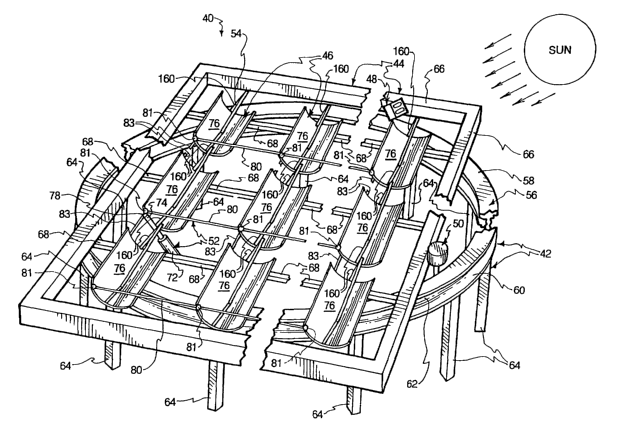
Figure 1 is a diagrammatic representation of one configuration or system
according to
the present invention, which system is generally designated 40. System 40
comprises a lower
stationary or static frame 42, an upper rotatable frame 44, mounted for
movement upon the
9
CA 02442143 2003-09-23
WO 02/097341 PCT/USO1/25900
stationary frame 42, an array of parabolic trough-shaped reflectors, generally
designated 46,
carried by the upper frame 44, an optical sun-locating control, generally
designated 48, carried
by the upper frame 44, a rotational drive mechanism, generally designated 50,
by which the upper
frame 44 is rotated about the lower frame 42 to maintain perpendicularity
between the rays of the
sun and the reflective surfaces of the parabolic reflectors comprising the
array 46 under control
of the optical sensor 48, a toggle reflector-tilting mechanism, generally
designated 52, by which
the angle of tilt of the parabolic reflectors of the array 46 is altered to
maintain said
perpendicularity as the sun travels across the sky and energy converters 54,
one being disposed
along the focal line of each parabolic reflector for converting reflected,
concentrated sunlight into
thermal and/or electrical energy.
An advantage of the present invention, when disposed in the form of apparatus
40, is that
it is modular, i.e. the number of reflectors can vary, ranging from a
relatively small number to
a relatively large number, depending upon the needs of a given facility.
In the form shown in Figure 1, the lower frame 42 comprises a curvilinear,
preferably
circular, track, generally designated 56, which, in cross section, is in the
form of an I-beam
comprising an upper flange 58, a lower flange 60 and a web 62. The track 56 is
preferably made
of steel and may be formed into the configuration shown in Figure 1 using
roller technology
available at a conventional steel plant. The track 56 is supported upon a
plurality of floor, roof
or ground-engaging legs 64. Legs 64 may be of any desirable type. All or some
of the legs 64
may be adjustable in length to provide for leveling, as herein described in
greater detail, or of
fixed length, where leveling is not a consideration in order to place the
track 56 in essentially a
horizontal orientation. The leg 64 may be made of steel construction, or some
other suitable
material may be used. Of course, the lower frame may be varied in its
construction from that
illustrated in Figure 1 without departing from the spirit or essential
characteristics of the present
invention, so long as a tracking of the sun and adequate capacity are
provided.
CA 02442143 2003-09-23
WO 02/097341 PCT/USO1/25900
With continued reference to Figure 1, the upper frame 44 is shown
schematically as
comprising a rectangular member 66, formed of hollow bar stock which is
rectangular in cross
section, for example, with interconnecting cross members 68 integrally joined
at the ends thereof
to the rectangular member 66, as by welding or use of conventional connectors
comprising, for
example, screw or nut and bolt fasteners. Upper frame 44, as illustrated in
Figure 1, is intended
to be fundamentally diagrammatic, to illustrate principles associated with the
present invention.
While not shown in detail in Figure 1, the upper frame 44 is rotatably
associated with the
lower fixed frame 42 in such a way, for example, that rollers traverse the
track 56 to and fro for
the purpose of maintaining perpendicular azimuth alignment between the rays of
the sun and the
disposition of each reflectors 46 of the array. Rotational displacement of the
upper frame 44 in
respect to the lower frame 42, in this regard, is achieved by the motor and
rotational drive
assembly 50, responsive to signals from the optical detector 48, as explained
herein in greater
detail. The optical detector 48 is illustrated and is being mounted to a
reflector frame associated
with one of the reflectors 76, at site 70, in Figure 1.
The toggle tilting mechanism comprises a motor-driven, reversible screw jack
72, the
proximal cylinder end of which is connected to the upper frame 44 and the
exposed distal piston
end 74 thereof is pivotally connected at site 78 to one or more reflector
frame members which
support the assemblage or array of reflectors 76 for unitary variation in
tilting to maintain altitude
perpendicularity with the sun. As the piston rod 74 is extended and retracted,
the reflectors 76
are tilted in unison by a toggle mechanism 80. The tilting mechanism 52 and
toggle mechanism
80 are illustrated diagrammatically in Figure 1. Each reflector 76 in a line
or tandem of reflectors
is non-rotatably connected to one or two adjacent reflectors by structural
members 83 which
accommodate the above-mentioned unitary tilting of the reflectors.
From the foregoing, it is clear that the upper frame 44 is, selectively
rotated upon lower
frame 42 pursuant to optical control signals and the trough-shaped parallel
reflectors 76 are
11
CA 02442143 2003-09-23
WO 02/097341 PCT/USO1/25900
adjusted in the angularity of their tilt, so that each reflector 76 is
essentially perpendicular to the
rays of the sun at all times during daylight hours. It is the use of reflected
line and point focused
sunlight that significantly distinguishes the present invention.
With reference to Figure 2, a somewhat modified lower frame 42' is
illustrated. This
embodiment illustrates the previously described circular track 56. A drive
chain 90 rests upon
the lower flange 60 of the erect I-beam track 56 to accommodate selective
rotation of the upper
frame in respect to the lower frame 42' in the manner explained above. In lieu
of leg 64,
telescopic legs, generally designated 64', are provided. Each leg 64' is
illustrated as comprising
sequential aligned leg segments 92 and 94 which are telescopically
interrelated so that the overall
length may be adjusted to level the track 56. To do this, a set screw 96 is
loosened, the correct
collective length for the leg segments 92 and 94 established and the set screw
96 threadedly
tightened through the leg segment 92 against the leg segment 94 to maintain
the desired
collective length. For added structural load-transferring stability, diagonal
braces 98 are
provided. The top of tube 92 and the top of each brace 94 is welded or
otherwise suitably
secured to the underside of lower track flange 60. The lower end of each
diagonal brace 98 is
welded or otherwise suitably secured to the associated tube 92.
The lower end of each tube 94 is illustrated as being welded to a plate or
pedestal 100,
which may be apertured so as to receive nut and bolt assemblies 102, with the
lower heads
thereof being imbedded in concrete for stability.
With reference to Figure 3, one type of suitable upper frame, generally
designated 44',
is shown, which implements principles of the present invention. The upper
frame 44' is
superimposed upon the circular track 56 and supports aligned pairs of
reflector frames, each
generally designated 110, by which the parabolic reflectors are rotated in
unison to adjust their
angle of tilt.
12
CA 02442143 2003-09-23
WO 02/097341 PCT/USO1/25900
The upper frame 44' is relatively small in overall size, as is the track 56.
The frame 44'
can be expanded to accommodate essentially as many reflectors as necessary for
any desired
facility by which reflected, line and point focused sunlight is transformed
into thermal and/or
electrical energy.
The upper rotatable frame 44', illustrated in Figure 3, is shown as comprising
end beams,
or trusses, preferably of steel, each generally designated 112, and an
interior beam of steel,
generally designated 114. Other types of suitable trusses or beams could be
used.
Each end beam 112 is illustrated as comprising upper and lower horizontal bars
I 16 and
118, which are integrally connected as by welded to several vertical crossbars
120. The interior
beam 114 comprises a plurality of horizontal members 122 and two vertical
members 124, such
that the horizontal members 122 and the vertical members 124 are welded
together. A plurality
of beams, generally designated 130, transversely connect to the end beams 112
and the
intermediate beam or beams 114 so that the upper rotatable frame 44' is a
rigid structure,
providing ample support for the reflectors, the energy converters and the
reflector frames.
As best illustrated in Figure 3, each parabolic trough-shaped reflector 76 is
supported by
a reflector frame, generally designated I40. While only eight reflector frames
140 are illustrated
in Figure 3, as mentioned previously, the number of reflectors and,
accordingly, the number of
reflector frames can be expanded significantly beyond the small array
illustrated in Figure 3.
Each reflector frame 140 is essentially rigid and comprises top and bottom
longitudinally-directed bars 142 and 144, connected by three trusses, each
generally designated
146. Each truss 146 comprises a linear bar 148, a parabolic bar 150 and a
plurality of cross bars
152, transversely spanning between bars 148 and 150, all ends of members 148,
150 and 152
being integrally connected as by welding.
Each reflector frame 140 also comprises at least one central longitudinally-
directed
support bar 154, welded to two end plates 156, by which the collective tilt of
the reflectors is
13
CA 02442143 2003-09-23
WO 02/097341 PCT/USO1/25900
rotationally adjusted in respect to the rotatable upper frame 44', as
hereinafter explained in
greater detail. End axle j ournals 158 span between each outside end plate 156
and one of the end
frames 112 and function as explained hereinafter in greater detail. Adjacent
interior plates 156
are also connected one to another by a j ournal mechanism, explained
hereinafter in greater detail,
by which joint tilting rotation of adjacent reflectors and reflector frames is
accommodated.
The previously mentioned energy converters 54, one ofwhich is carried by each
reflector
frame 110 at the focal line of the associated parabolic reflector, is
supported by two cantilever
arms 160 one disposed at each end of the converter 54. Each arm 160 is
connected by welding
or the like to the central bar 154 and one end truss 146 to rigidly hold the
associated converter
54 at the focal line of the associated reflector 76, the energy converter 54
bidirectional turning
with the reflector as it is turned utilizing the power toggle mechanism 52.
Each reflector 76, none of which is shown in Figure 3, is attached to each of
the three
associated parabolic members 150, spanning the full length and width of the
associated reflector
support frame 110. Rivets or other suitable fasteners may be used to connect
the reflector to the
associated parabolic members 150. Each reflector 76 is preferably comprised of
polished sheet
aluminum or other suitable highly reflective material.
The energy converter 54 for each reflector 76 is supported at the respective
ends thereof
by arm 160, which not only rigidly connects to one of the ends of the
associated converter 54 but
also at sites 151 and 153 (Figure 5) to the associated reflector frame 140, as
by welding.
Each converter 54 and the associated support arms 160 are typically hollow to
accommodate liquid flow within a pipe to, through and from the converter 54
for the purpose of
converting line focused or point focused reflected sunlight to thermal energy
per se or in
conjunction with the cooling of solar cells, which are exposed to very high
temperatures during
conversion of reflected point focused sunlight to electrical energy, as
hereinafter explained in
greater detail.
14
CA 02442143 2003-09-23
WO 02/097341 PCT/USO1/25900
From the foregoing, the significance of the illustration comprising Figure 4
should be
readily apparent, namely that the tracking optical sun detector 48
continuously senses the location
of the sun in the sky relative to the azimuth and altitude of the array of
reflectors 76 and, to the
extent, the reflectors 76 are not collectively perpendicular to the sun, the
differential is detected
by the bidirectional optical sensor 48 and signals are issued to the motor and
rotational drive 50
to place the axes of the reflectors into a position of perpendicularity with
the sun. In addition,
signals are issued by the detector 48 to the motor and toggle tilting
mechanism 52 by which the
tilt of the parabolic reflectors is placed in a perpendicular relationship
with the rays of the sun,
perpendicularity being intersection of the rays of the sun with a line drawn
between the upper and
lower edges 170 and 172 (Figure 4) of each reflector.
Thus, both from altitude and an azumith point of view, the reflectors 76 are
continuously
adjusted so that reflector perpendicularity is maintained with the rays of
sunshine striking each
parabolic trough-shaped reflector. As a consequence, sunlight reflected from
each reflector 76
is line-focused upon the associated energy converter 54, where the reflected,
line-focused solar
energy is either converted to thermal energy or point-focused and converted to
electrical energy,
as explained herein in greater detail.
The relationship between the reflector trusses 150 and the trough-shaped
parabolic
reflectors 76 is best illustrated in Figure 5, in enlarged fragmentary
perspective. In the
configuration of Figure 5, two central longitudinal reinforcing bars 154 and
154' are provided,
in lieu of one, to enhance structural integrity.
In reference to Figure 6, the optical detector 48 is illustrated in greater
detail. Detector
48 comprises an external housing 170 which supports two shadow devices 172 and
174. Shadow
bar device 172 comprises a shadow bar 173, by which lack of perpendicular
alignment between
the rays of the sun and the altitude or tilt angle of the reflectors is
detected by one or more
internal photocells. Shadow bar detector 174 comprises a shadow bar 175, by
which lack of
perpendicular azimuth or rotational alignment is detected by one or more
internal photocells.
CA 02442143 2003-09-23
WO 02/097341 PCT/USO1/25900
When the internal photo cells detect a lack of either altitude or azimuth
alignment via shadows
caused by rays ofthe sun striking the shadow bars 173 and/or 175, signals are
issued to the motor
and rotational drive 50 andlor motor and toggle tilting mechanism 52 to bring
the rotational
position and the tilt position of the array of reflectors again into
perpendicularity with the rays
of the sun, after which the detector signals cease because no detectable
shadow exists and
rational and/or tilt adjustments stop.
Reference is made now to Figures 7 and 8 with particularity in respect to the
types of
energy converters which may be disposed at converter site 54. Figure 7
illustrates a converter
by which solar energy is transformed into thermal energy, while Figure 8
illustrates an
embodiment by which solar energy may be reflected and point focused for
conversion into
electrical energy. In respect to Figure 7, a tube 176 is disposed at the focal
line of reflector 76
so that the rays of line focused, reflected sunlight 178 impinge directly in
concentrated form upon
the thermally conductive material, such as copper, from which the tube 176 is
formed.
As the rays of reflected, line focused sunshine heat the tube I76, liquid is
displaced from
source 178 through the tube 176 at a flow rate controlled by flow control 180.
The liquid so
displaced is heated by the elevated temperature of the tube 176, typically to
a very high
temperature along the focal line at 54, with the effluent hot water or steam
being delivered, for
example, to a heat exchanger 182, where the liquid or steam emerging from tube
176 is used to
heat another segregated liquid, which is discharged from the heat exchanger as
effluent from tube
I 84. The liquid entering the heat exchange 182 as influent is, after the heat
exchanged process,
discharged along tube 186, and is returned to the source 178.
The liquid contained within source 178 and circulated as indicated above may
be, in
selected instances, water and, in other instances, a mixture of alcohol and
water, as chosen by one
skilled in the art. Other suitable liquids may be used.
16
CA 02442143 2003-09-23
WO 02/097341 PCT/USO1/25900
With specific reference to Figure 8, the line focused reflected solar energy
188 is caused
to be point focused, for example by a series of Fresnel lenses, as shown
diagrammatically at 188
in Figure 8. The point focused rays 188 of sunlight are impinged upon a series
of solar cells 190,
the characteristic of which transforms the point of focus reflected sunlight
188 into direct current
electrical energy, which may be sold, stored or directly utilized. Tn the
alternative, the DC
electricity can be passed through a DC/AC converter 192 to create alternating
current electricity,
which may be stored, sold or directly utilized.
While not shown in Figure 8, it is to be appreciated that the solar cells 190
typically are
mounted or otherwise made contiguous to the external surface of a cooling tube
to hold the
temperature of the solar cells 190 within a lower acceptable temperature
range. As a
consequence, liquid contained within the cooling tube is heated, which heated
liquid may be
utilized in any suitable fashion including but not limited to the one
described above in respect
to Figure 7.
As mentioned earlier, in conjunction with Figure 3, the reflector frames 140
are
collectively assembled so as to rotate in unison around journals, such as end
axle/journals
assemblies 158, the journals/assemblies axles, of any string or tandem of
aligned reflector
frames 140 being disposed along a common axis. Each journal/axle assembly 158
essentially
comprise a central short axle such that diametrically reduced ends of the axle
fit within opposed
sleeves at opposite ends of the axle. Each axle is stabially secured to the
upper frame 44, 44;
while the sleeves rotate around the associated axle with the reflector frames.
Similarly, journalslaxle assemblies 194 (Figure 9) are interposed between
sequential
aligned reflectors 76 and comprise outer sleeves 196 at each end of the j
ournal and a central short
axle comprising reduced diameter ends 198 rotatably disposed within the
sleeves 196. The axles
comprising ends 198 are rigidly connected to the upper frame 44, 44; while the
sleeves 196 are
17
CA 02442143 2003-09-23
WO 02/097341 PCT/USO1/25900
connected to and rotate with the reflector frames 140. As can be seen from
inspection of Figure
9, the aligned axles of any aligned group of reflector 76 creates an axis of
rotation.
The previously mentioned toggle mechanism 52 may comprise a motor-driven screw
drive, generally designated 200, which comprises an internally helically
threaded cylinder 202
and a rod 204, the internal end of which is threadedly engaged with the
interior threads of the
cylinder 202, to accommodate extension and refraction. The distal end 206 of
the rod 204 is
pivotally connected, at 208, to a bracket comprising a pair of lugs 210. Lugs
210 are integrally
connected, by welding, fasteners or the like to a pair of toggle displacement
bars 212 (only one
of which is seen in Figure 9), which are reciprocated to an fro by the motor-
driven extension and
retraction of rod 204. The distal ends 214 of the two toggle bars 212 are
respectively connected
pivotally at 216 to, adjacent anchor plates 218 welded or otherwise secured to
juxtaposed parallel
trusses 146. The connection site 216 is eccentrically located to facility
rotation of the reflector
frames 140 around the axles.
Thus, as detector 48 at shadow bar 173 photoelectrically determines the need
to adjust
the tilt of the array of reflectors, a signal is sent to the screw drive motor
230 (Figure 12), which
in turn causes extension or retraction of the rod 104, which in turn displaces
the toggle bars 212
fore or aft to pivot the array of reflectors in unison around the axles upon
which the reflector
frames 140 are rotatably mounted. See Figure 9. The toggle bars 212
consecutively pivotably
and eccentrically connect at 216 to one of each line of reflector frames 140,
as best illustrated in
Figure 9, so that all reflector frames 140 and all reflectors 76 rotate
together around parallel
horizontal axes.
Keep in mind that the detector 48 (Figure 6) is mounted to one of the trusses
146 (Figure
6) so that the shadow bars 173 and 17S are in a plane essentially parallel to
the plane containing
bar 148 of the truss 146 which supports the detector 48.
18
CA 02442143 2003-09-23
WO 02/097341 PCT/USO1/25900
Specific reference is now made to Figure 10 through 12, which illustrate one
way in
which the toggle mechanism 52 may be connected to adjacent reflector frames
146. The two
toggle bars 212 are illustrated as being parallel and hollow structural
members having a
rectangular cross section (Figure 10). The toggle connection plates 218 are
illustrated in Figure
as extending beyond the two adjacent reflectors 76, as does the distal ends of
each toggle bar
212. The pivotal connectors 216 are illustrated as being nut and bolt
assemblies pivotally passing
through, in each case, the associated toggle bar 212 and the connection plate
218, to
accommodate the previously mentioned changes in the tilt angle of the array of
reflectors 76 and
reflector frame 140.
Figure 11 is similar to Figure 10, but illustrates the motorized tilt
adjusting mechanism
52 for the array of reflectors 76 from a perspective essential opposite to
perspective of Figure 10.
The screw drive 200 is again illustrated in Figure 12, which further depicts
motor 230,
conventionally connected to transmission or differential 232, so that when the
reversible motor
230 is actuated by a signal from the optical detector 48 (Figure 6) to
unitarily alter the angular
relationship of the array of reflectors in respect to the vertical, the screw
drive 200 is extended
or retracted, depending upon the displacement necessary to restore the angle
of tilt of the
reflectors to perpendicularity with the rays of the sun.
As mentioned earlier in conjunction with Figure 1, the upper frame 44 is
rotatably
mounted upon the curved track 56, which track, as illustrated, is in the form
of a circular I-beam.
More specifically, the upper rotatable frame 44 is made selectively rotatable
in respect to the
stationary track 56 using a plurality of load-transferring trucks 250, one of
which is illustrated
in Figure 13. Each truck 250, as illustrated, comprises a U-shaped frame,
generally designated
252, preferably formed of steel comprising two pairs of lugs or ears 254 and a
U-shaped bridge
256. The lugs 254 and the bridge 256 are held in spaced relation in respect to
the I-beam track
56, as best illustrated in Figures 14 and 15. An upper frame displacement
roller 258 is rotatably
19
CA 02442143 2003-09-23
WO 02/097341 PCT/USO1/25900
supported by each lug 254 upon a shaft 260. Each shaft 260 is non-rotatably
carried by the
associated lug 254 in the manner illustrated in Figure 14. As best seen in
Figures 13 and 14, each
of the four rollers or casters 258 fractionally engage and rotatably travel
along the upper surface
of lower flange 60 of the I-beam track 56.
Each truck 252 is rigidly connected to the upper, rotatable frame 44. This may
be as
illustrated in Figure 13, i.e., by use of two angle irons welded in spaced
relation to the upper
horizontal surface ofthe associatedbridge 256. See Figures 13 and 15,
specifically. The spacing
between the vertically directed legs of the angles 262, shown at 264 (Figure
15) accommodates
snug reception of one horizontal member 45 of the upper frame 44. Nut and bolt
assemblies 266
(Figure 13) are illustrated as being utilized to fasten each angle piece 262
to the upper frame
member 45.
Thus, a plurality of idler trucks 250 are used to provide Load transfer to the
lower flange
60 of the I-beam track 56 and to accommodate rotation of the upper frame 44 in
respect to the
lower frame responsive to location correcting signals issued from the optical
detector 48.
To prevent the upper frame from jumping the track 56, each truck 250 is
equipped with
vertically directed, web-engaging opposed rollers 268. See Figure 15. These
rollers maintain
appropriate alignment between the upper frame and the trucks 250 in respect to
the lower frame
and circular track 56. The rollers 268 contiguously engage the opposite
surfaces of the web 52
of the I-beam 56, each being rotatably mounted upon L-shaped axle 270, which
accommodates
rotational travel by the rollers 268 along the web 62 as the rollers 258
correspondingly travel
along the upper surface of the lower flange 60 of the I-beam 56.
Reference is now made to Figures 2 and 16 through 19, which collectively
illustrate the
motor and rotational drive mechanism 50. The mechanism 50 comprises a
reversible motor 280,
which is activated and deactivated by signals derived from the optical sensor
48 by which the
CA 02442143 2003-09-23
WO 02/097341 PCT/USO1/25900
array of reflectors are maintained, from an azimuth point of view, in a
perpendicular orientation
with respect to the rays of the sun.
Reversible motor 280 rotates a differential or gear transfer box 282, which in
turn rotates
an external drive shaft 284 (Figure 18), which turns a drive sprocket 286, non-
rotatably secured
to the shaft 284. The sprocket 286 turns to engage successive links 288 of the
previously
mentioned drive chain (Figure 2) 90. The chain drive 90 is statically secured,
as by welding, at
its distal and proximal ends to the static I-beam track 56, providing enough
length to
accommodate engagement with the sprocket 286. Rotational displacement of the
sprocket 286
causes the sprocket to walk, in one direction or the other, along the links
288 of the chain 90 to
rotate the upper frame 44 upon the lower frame 42 to maintain reflector
perpendicularity with the
sun from sunrise to sunset during the longest day of the year in any location
upon the face of the
earth. The chain 90, between welded ends, rests upon the top surface of the
lower flange 60,
as shown in Figures 2, and 17-19. Thus, the chain drive 90 is loose at all
locations, except where
it is welded to the track 56 at its opposed ends. The length of the chain
drive 90 is selected so
as to snugly pass around the sprocket 286 in taut relation.
Thus, rotation by motor 280 of the shaft 284 and the sprocket 286, either
clockwise or
counterclockwise, will result in the upper frame 44 turning in respect to the
lower frame, in one
direction or the other, to maintain azimuth perpendicularity with the sun, in
the manner described
earlier. Note that the motor 280 and the differential 282 are statically
mounted upon a mounting
plate 292 of the upper frame 44. Mounting plate 292 is preferably formed of
steel and is bolted,
welded or both to the upper frame 44. Signals from the optical detector 48
turn the reversible
motor 280 on and off in one direction or the other consistent with optical
detection of non-
azimuth perpendicularity between the array of reflectors and the location of
the sun in the sky.
As seen best in Figures 17 and 18, the chain 90 comprises a U-shaped segment,
generally
designated 300, which passes tautly around the sprocket 286. The sprocket
contains teeth, sized
21
CA 02442143 2003-09-23
WO 02/097341 PCT/USO1/25900
and shaped to engage hollow spaces within each link 288 of the chain 90.
Accordingly, as the
sprocket 286 is rotated by motor 280, the differential 282 and the shaft 284,
successive links 288
of the chain drive 90 are engaged by the sprocket teeth causing the upper
frame 44 to rotate along
the track 56 in the manner explained above to preserve the mentioned
perpendicularity. The
motor 280 is reversible and, therefore, shaft 284 may be turned in either
direction to move the
upper frame 44 clockwise or counterclockwise along the lower stationary track
56.
The present invention is not confined to any specific form for the lower
stationary frame
and/or the upper displaceable frame. Similarly, the present invention may be
implemented by
placing it above the roof of an existing building supported by columns, on an
existing flat or
sloped roof of an existing building, on or immediately above an existing
surface, such as a
parking lot, for example, on columns above an existing surface (to allow
traffic underneath) or
in any other suitable location.
Reference is made to Figure 20, which illustrates one way of mounting an
embodiment
ofthe present invention comprising a lower static frame 42' comprising a
curved track 56', which
is also static, supported upon a plurality of columns 310 (only one of which
is illustrated),
wherein the proximal end 312 of each column extend into the ground and is
encased in concrete
314, for stability.
Each column 310 is secured as by welding at sites 314 to the lower static
truss 42'.
Frame 42' is illustrated as comprising a plurality of members 316, arranged
conventionally to
form triangular supports. The structural members 316 may be of any appropriate
cross sectional
shape, preferably formed of steel.
The track 56' is illustrated as being circularly disposed with the flanges 58'
and 60' being
vertically not horizontally directed and the web 62' being horizontally
directed. The lower edges
of the flanges 58' and 60' contiguously engage and are secured to the lower
frame 42', as by
welding. The load comprising the reflectors, the reflector frames, the upper
rotatable frame 44'
22
CA 02442143 2003-09-23
WO 02/097341 PCT/USO1/25900
wind and/or snow comprise a substantial load transferred through a plurality
of trucks 252' and
rollers 258' to the web 62' of the track 56'.
Reference is now made to Figure 21 which illustrates one way in which large
installations
in accordance with the present invention may be implemented. More
specifically, two or more
static tracks 56, of the type previously described, are concentrically
provided so that a large array
of reflectors and reflector frames carried upon a displaceable upper frame may
rotate in unison
along the plurality of tracks 56 as earlier described. Thus, the size of any
installation utilizing
the present invention is flexible, ranging from a very small installation
comprising a few
reflectors to an extremely large installation comprising a large number of
reflectors.
Where a sequence of reflectors and reflector frames aligned longitudinally one
with
another is utilized, in lieu of the motor and toggle tilting mechanism 52,
described above, a
torque tube, generally designated 330 in Figure 22 may be used. The torque
tube 330 may be of
hollow tubular steel construction to which is attached a plurality of tracking
arms 332, joined,
respectively, in an eccentric disposition to each reflector frame 140 of a
line of such frames.
Rotation of the torque tube 330 will in turn alter the tilt angle of the
associated reflectors 76 and
reflector frames 140. This rotation is achieved by one or more drive arms 334
integrally
connected as by welding to the tube 330. The distal end 336 is pivotally
connected to the distal
end of the previously described rod 204 of the screw drive 200 so that
extension and retraction
of the rod 204 rotates the torque tube 330 through the drive arm 334 clockwise
and
counterclockwise, respectively, for the purpose of adjusting the tilt of the
related reflectors to
preserve perpendicularity with the rays of the sun, as mentioned earlier. A
plurality of torque
tubes may be used as would be appropriate. More than one screw drive 200 may
be used in
conjunction with any given torque tube without departing from the spirit of
the present invention.
As mentioned previously, when the energy converter 54 transforms solar energy
into
thermal energy, a hollow tube 340 (Figure 24) may be located at the focal line
of the associated
23
CA 02442143 2003-09-23
WO 02/097341 PCT/USO1/25900
reflector. Tube 340 may be of any thermally conductive material, such as
copper. A liquid is
displaced through the hollow interior 342 as the line-focused sunlight 344
impinges upon and
heats the tube 340, causing the liquid contained in the tube 340 to be heated
from one
temperature to a significantly higher temperature.
In the configuration of Figure 24, a U-shaped housing 345 of suitable
material, such as
sheet metal or, plastic surrounds part of the tube 340 within the housing 345.
The housing 345
comprises opposed lower lips 346, which accommodate sheet reception and
retention of
transparent lens 348, which may be glass or synthetic resinous material. The
tube 340 is
illustrated as being imbedded, in part, in a block of insulation 350, so that
the heated Iiquid
within the hollow interior 342 of the tube 340 does not undesirably or
prematurely cool. The
block of insulation 350 is illustrated in Figure 24 as surrounding
approximately 260 degrees of
the tube 340 when viewed in cross section, i.e., the top and most of the two
sides, leaving the
bottom of the tube 340 open fox impingement of the reflected Line-focused rays
344 of the, sun
through the lens 348 directly upon the exterior of the tube 340.
In lieu of the configuration illustrated in Figure 24, the embodiment of
Figure 25 may be
utilized wherein the block of insulation 350' extends only along 180 degrees
of the exterior. tube
340 when viewed in cross section.
As mentioned earlier, some or all of the focus lines of the parabolic trough-
shaped
reflectors 76 may be equipped with solar-to-electricity converters. More
specifically, in reference
to Figure 26, converter 54 may comprise a housing 360 having a tapered hollow
interior. The
top of 362 may be equipped with a plurality of aligned Fresnel lenses 364.
Each Fresnel lens 264
comprises concentric grooves upon which is impinged the reflected line-focused
sunshine 366.
The grooves of each Fresnel lens converts the reflected line-focused sunshine
366 to reflected
point-focused sunlight 368. Each segment ofpoint-focused sunlight is
impingedupon one ofthe
solar cells 190. Several commercially available solar cells exist any of which
may be used as
24
CA 02442143 2003-09-23
WO 02/097341 PCT/USO1/25900
solar cells 190. While the input to each solar cell 190 is solar energy, the
output is electrical
energy, communicated from the solar-to-electricity converter 54 upon
electrical leads 370. This
electrical energy is direct current electricity. If alternating current
electricity is desired, DC/AC
converter 192 may be utilized from which conventional household electricity
may be derived.
Continued reference is made to Figure 26, which illustrates a circular funnel-
shaped
secondary solar energy reflector 372 disposed above each solar cell 190, by
which any stray solar
energy is reflected so that all sunlight passing through the associated
Fresnel lens 264 is caused
to impinge upon the associated solar cell 190.
As mentioned earlier, it is ordinarily appropriate to cool the solar cells
190. This may
be done by placing each solar cell contiguously on the exterior of a cooling
tube 374, through
which liquid coolant is displaced to not only cool the solar cells 190 but to
convert the heat so
transferred to useable thermal energy.
In lieu of the circular funnel-shaped secondary reflectors 372, the reflectors
380 of
Figures 27 and 28 may be used. Each reflector 380 is rectangular in cross
section with four
downwardly tapered flat walls intersecting at diagonally-disposed corners,
with a solar cell at the
bottom of each reflector 380. In either case, the internal surface of
secondary reflectors 372
and/or 380 is selected to accommodate full reflection of any stray sunlight so
that all sunlight
passing through any Fresnel lens 364 is caused to impinge upon the associated
solar cell 190.
Reference is now made to Figures 29 and 30, which illustrate another reflector
embodiment of the present invention with the support frame on the convex or
back side of the
reflector, as opposed to being on the front or concave side. More
specifically, all or any one of
the parabolic trough-shaped reflectors 76 may be supported on the back or
reverse side thereof
to provide a slightly more unencumbered reflective surface. As shown in Figure
29, reflector 76
is supported by a reflector frame 400. Reflector frame 400 comprises the
previously described
CA 02442143 2003-09-23
WO 02/097341 PCT/USO1/25900
upper and lower longitudinal reinforcement of members 142 and 144. Midway
between the
members 142 and 144, on the back side of the reflector 76, are two contiguous
longitudinally
extending rectangular supports 154" comprising, at each end, blunt edges 155
essentially aligned
with the adjacent end edge of the associated reflector 76.
A plurality of parabolically shaped ribs, each generally designated 402, span,
at spaced
intervals, between respectively member 142 and one of the two central members
154" and
between member 144 and the other of the two central support members 154', as
illustrated in
Figure 29.
Each rib 402, as best illustrated in Figure 30, comprises a U-shaped brace
having opposed
outwardly directed flanges 404, which are contiguous with and adhered by a
simple bonding
agent or the like to the back surface of reflector 76 at interface sites 406.
The each rib 402
further comprises opposed parallel side walls 408, which respectively merge
with the associated
one of the two flanges 404 essentially through a 90 degree angle. The spaced
side walls 408
merge respectively at 90 degree corners with a back wall 410, which is cut at
opposite ends into
integral end tabs 412 and 414. Each end tab 412 is contiguous with and bonded
to member 142
or member 144, depending upon whether the rib is a top rib or a bottom rib.
See Figures 31 and '
32.
In addition to the foregoing, the reflector frame 402 will be rotatably
connected to the
previously described axle structure and eccentrically to the previously
described toggle
mechanism to accommodate rotation around a horizontal axis to accommodate
periodic changes
in the tilt of the reflector 76 to preserve perpendicularity with the rays of
the sun, for the purposes
set forth above.
The invention may be embodied in other specific forms without departing from
the spirit
of the central characteristics thereof. The present embodiments therefore to
be considered in all
respects as illustrative and not restrictive, the scope of the invention being
indicated by the
26
CA 02442143 2003-09-23
WO 02/097341 PCT/USO1/25900
appended claims rather than by the foregoing description, and all changes
which come within the
meaning and range of equivalency of the claims are therefore intended to be
embraced therein.
What is claimed and desired to be secured by Letters Patent is:
27