Note: Descriptions are shown in the official language in which they were submitted.
CA 02442271 2003-09-25
WO 02/076357 PCT/EP02/03263
1
TAMPON HAVING SPIRALLY SHAPED GROOVES
The invention relates to a tampon for feminine hy-
giene, and to a method and an apparatus for producing the
same, as are described in US Patents no. 5,911,712;
5,813,102 and 5,832,576.
The tampon according to US Patent 5,911,712 has an
insertion end, 'a recovery end with a recovery tape, a
central section extending therebetween, and comprises a
compressed, generally cylindrical, solid fibrous core,
from which relatively uncompressed longitudinal ribs
extend radially outward. Each rib is separated from adja-
cent ribs in the vicinity of the compressed fiber core to
an extent which is greater than that extent to which such
a rib is separated from an adjacent rib remotely from the
compressed fiber core. In this connection, the fiber core
is pressed more strongly in the central area than in the
area of the recovery end of the tampon. Furthermore, the
recovery end of the tampon is provided with a finger
recess and the insertion end with a round dome. The ap-
proximately circular diameter of the fiber core is up to
mm. Finally, the tampon is at least partially sur-
rounded by a liquid-permeable sheathing.
The method described in US Patent 5,813,102 for pro-
ducing a tampon envisages the following steps: rolling up
a length of a continuous fibrous web to form a generally
cylindrical tampon blank with a circumferential surface;
simultaneous radial pressing of narrow, strip-shaped
sections of the circumferential surface of the tampon
blank arranged in a spaced manner to form a number of
longitudinal grooves which are separated from one another
by relatively uncompressed longitudinal ribs which extend
radially outward from a relatively compressed core, the
core being compressed to a smaller extent in the area of
the recovery end of the tampon than in its remaining
area; and pressing of outer ends of the longitudinal ribs
radially inward to form a soft, smooth circumferential
CA 02442271 2003-09-25
WO 02/076357 PCT/EP02/03263
2
surface, while the relatively uncompressed fibrous struc-
ture of the ribs is preserved. The pressing of the narrow
circumferential sections of the tampon blank can take
place at room temperature, while the pressing of the
outer ends of the longitudinal ribs can be carried out at
elevated temperature. Furthermore, a finger recess and a
round dome can be provided at the recovery end and the
insertion end of the tampon respectively. Lastly, a liq
uid-permeable sheathing is fixed on the fibrous web at
least in parts, so as to provide a liquid-permeable layer
on at least part of the outer surface of the tampon
blank.
The apparatus described in US Patent 5,832,576 for
producing a tampon with an insertion end, a recovery end
and a recovery tape comprises: a press for preforming a
preform with a press axis, an inlet opening, an outlet
opening and a plurality of similarly configured press
jaws which are arranged in a plane running perpendicu-
larly to the press axis, each press jaw having a pressing
head which is oriented radially with respect to the press
axis, a pressing shoulder which is laterally adjacent to
the pressing head, is offset radially outwardly with
respect to the pressing head and has a larger pressing
surface than the pressing head, the press jaws being
simultaneously concentrically movable in relation to the
press axis between a closed position and an opened posi-
tion, and, in the closed position, the press jaws being
supported on one another on mutually opposite longitudi-
nal sides and the radial distance between the press axis
and one pressing head at one of the inlet or outlet open-
ings being greater than the distance between the press
axis and the pressing head at the other of the two open-
ings, and a stationary shaping tool which is arranged
coaxially with respect to the press axis of the press,
has an inlet opening which corresponds to an outer diame-
CA 02442271 2003-09-25
WO 02/076357 PCT/EP02/03263
3
ter of the preform and an outlet opening which corre-
sponds to an outer diameter of the tampon. -The radial
distance between the pressing heads and the press axis
can be greater, if appropriate in a steplike manner, in
the direction of the outlet opening of the press. The
longitudinal side of each press jaw in each case bounding
the pressing shoulder forms a supporting surface which is
supported in each case on a sliding surface which is
formed by the longitudinal side bounding the pressing
head of the adjacent press jaw, parts of the supporting
surface and sliding surface bounding a gap which extends
radially with respect to the press axis and is open in
the direction of the press axis and is closed in the
closed state of the press. Moreover, the supporting sur-
faces on the side of the press jaws arranged in the cir-
cumferential direction of the press axis are provided
with supporting ribs parallel to the press axis, which,
in the closed position of the press, bear against an
opposite sliding surface of the adjacent press jaw and
form a closed end of said gap between adjacent press
jaws, which gap is radial with respect to the press axis.
Side flanks of the pressing head of each press jaw con-
verge slightly in the direction of a narrow pressing
surface at the radially inner end of each pressing head.
The press consists of eight or more press jaws. The sta-
tionary shaping tool is a smoothing bush with a partially
conical channel which continuously produces the final
shape of the tampon and with a clear end section with a
cross section which corresponds approximately to the
final cross section of the tampon. In this connection,
the clear cross section of the inlet opening of the
smoothing bush, which lies coaxially opposite the outlet
opening of the press, is determined by the cross section
of the outlet opening of the press, when the press jaws
are closed. Guide ribs inside the smoothing bush corre-
spond in number to the press jaws of the press and occupy
CA 02442271 2009-10-27
'77060-26
4
the same angular position in relation to the press axis
as the pressing heads. The pressing heads of each press
jaw project beyond a corresponding end of an associated
pressing shoulder, and a round fixing disk surrounding
the inlet opening of.the smoothing bush is arranged oppo-
site the outlet opening of the press, a front side of the
fixing disk perpendicular to the press axis being pro-
vided with grooves which are oriented radially with re-
spect to the press axis and in which the pressing heads
engage. A revolving disk is arranged behind the outlet
opening of the smoothing bush, on which a cylindrical
hollow mandrel for transferring the tampon to a packing
station is coaxially fixed. The clear cross section of
the hollow mandrel corresponds to the smallest clear
cross section of the smoothing bush. Lastly, a sleeve-
shaped pusher is provided, which has a diameter which is
smaller than that of the inlet opening of the press in
the open position of the press jaws and serves to feed a
tampon blank into the press, a coaxial ejector, which has
a diameter which is smaller than the outlet opening of
the press in the closed state of the press jaws, being
arranged movably to and fro coaxially in the pusher and
serving for ejecting the preform out of the press through
the smoothing bush into the hollow mandrel.
An object of embodiments of the invention is to improve the tam-
pon, the method and the apparatus as described above in
such a manner that the risk of leakage after the tampon
'has been put into use is reduced considerably by extend-
ing the time over which the tampon absorbs body fluid,
and by enlarging the surface of the tampon and increasing
the fiber quantity available for immediate absorption of
body fluid after the introduction of the tampon, in par-
ticular in the area of the fiber core.
As a result of the longer distances the body fluid has to cover on account of
the
CA 02442271 2009-10-27
-77060-26
spiral design of the longitudinal ribs and of the spiral
longitudinal grooves extending between these along the
surface of the tampon, and as a result of the associated
longer dwell time of the liquid in the spiral longitudi-
nal grooves, the absorption and expansion capacity of the
solid fiber core, which ensures the stability or bending
resistance of the tampon during introduction of the same
into the body cavity, is utilized in a considerably bet-
ter manner.
Accordingly, an aspect of the invention relates to a tampon for
feminine hygiene, having an insertion end, a recovery
end, a recovery tape, and a generally solid core made of
highly compressed fibrous material which is compressed
radially with respect to the tampon axis and from which
at least partially relatively uncompressed longitudinal
ribs extend radially outward at equal circumferential
angle intervals and between the insertion end and the
recovery end and are separated from one another by longi-
tudinal grooves, the longitudinal ribs and the longitudi-
nal grooves being spirally shaped.
The spiral longitudinal ribs can each extend over a
circumferential angle a of up to at least 150 of the
tampon.
According to an advantageous embodiment of the in-
vention, the circumferential surface of the tampon and
its fiber core can be curved in a barrel-shaped manner.
As a result of the associated lower compression of the
fibrous material over the entire cross section of the
tampon in the area of its barrel-shaped convexity, not
only the fibrous material in the form of the spiral lon-
gitudinal ribs surrounding the solid fiber core, but also
the in contrast relatively greatly compressed fibrous
material of the fiber core, can, when acted on by body
fluid, expand more rapidly and moreover absorb a greater
quantity of liquid.
CA 02442271 2003-09-25
WO 02/076357 PCT/EP02/03263
6
According to a further embodiment of the invention,
however, the circumferential surface of the tampon and
its fiber core can also be substantially cylindrical.
The spiral longitudinal grooves can be open radially
to the outside, at least in the area of the compressed
cylindrical fiber core. As a result, a particularly large
surface and fiber quantity are available for immediate
liquid absorption right into the area of the fiber core
of the tampon, which is widened in a slightly barrel-
shaped manner.
In this connection, the possibility preferably ex-
ists that each spiral longitudinal rib of the tampon is
separated from adjacent spiral longitudinal ribs in the
vicinity of the compressed fiber core to an extent which
is greater than that extent to which such a spiral longi-
tudinal rib is separated from an adjacent spiral longitu-
dinal rib remotely from the compressed fiber core.
According to an especially preferred embodiment of
the invention, however, the spiral longitudinal grooves
can also be closed, at least at the circumferential sur-
face of the tampon. In this case, it is advantageous if
opposite side flanks of adjacent spiral longitudinal ribs
touch one another only in the area of their radially
outer ends and close the spiral longitudinal grooves
radially outward, in order to form spiral liquid guide
ducts between the fiber core and the closed circumferen-
tial surface of the tampon. In this connection, the spi-
ral liquid guide ducts are preferably open at the inser-
tion end and at the recovery end of the tampon.
The method of producing the tampon according to the
invention comprises the steps:
providing a tampon blank of tangled fibrous mate-
rial;
compressing the tampon blank on narrow generating
lines of its circumferential surface, which are
separated from one another by equal circumferential
CA 02442271 2009-10-27
.77060-26
7
angles, forming longitudinal grooves and a substan-
tially cylindrical fiber core with a high degree of
compression, from which relatively uncompressed lon-
gitudinal ribs extend radially outward, the tampon
blank being pressed on spiral generating lines in
order to form spiral longitudinal grooves and spiral
longitudinal ribs parallel thereto in order to en-
large the absorbent surface of the tampon.
The spiral generating lines of the circumferential
surface of the tampon blank can each be pressed over a
circumferential angle _ of up to at least 150 of the
tampon blank. A method step may be preferred, however, in
which the spiral generating lines of the circumferential
surface of the tampon blank are each pressed over a cir-
cumferential angle a of 80 to 120 . Furthermore, it is
advantageous to press the fibrous material of the tampon
blank under heat action, for example at 80 to 120 C.
Moreover, the spiral longitudinal ribs and longitudinal
grooves should be smoothed after pressing. While it is
true that smoothing the spiral longitudinal grooves and
longitudinal ribs at room temperature is preferred, it
can also be carried out at a temperature of 80 C to 120 C,
if this 'is desired, for example in consideration of the
fiber composition, the size of the tampon and the press-
ing conditions.
After the pressing of the spiral longitudinal ribs
and spiral longitudinal grooves, it is recommended that
the radially outer ends of the longitudinal ribs are
subjected to a slight concentric pressure, so thattlie
ends of adjacent longitudinal ribs are laid on one an-
other and form a soft, closed circumferential surface of
the tampon, the radially outwardly open longitudinal
grooves on the circumferential surface of the tampon
being closed, so that liquid guide ducts within the
closed circumferential surface are produced from the
CA 02442271 2003-09-25
WO 02/076357 PCT/EP02/03263
8
longitudinal grooves, which ducts are preferably open at
the insertion end and at the recovery end of the tampon.
In this way, a considerable increase in the absorption
capacity of the tampon is achieved along with very com-
fortable introduction for the user.
The preform is advantageously shaped in a single
pressing operation, preferably with the application of
heat. This is recommended especially when use is made of
at least a certain quantity of fibers which, to improve
absorption capacity, have an irregular cross section and
consequently a strong memory effect.
An apparatus according to the invention for produc-
ing the tampon comprises:
a press having press jaws of equal dimensions which
are arranged in a star formation with respect to the
press axis x and can be moved synchronously in a
common plane radially with respect to the press axis
x between their open position and closed position
and, in their closed position, are supported on one
another on their mutually opposite longitudinal
sides;
a stepped pressing surface on each press jaw,
- the pressing surfaces of the press jaws forming a
press opening of round cross section with a length
in the range from 40 to 70 mm;
- each pressing surface having a pressing blade which
is oriented toward the press opening, and a pressing
shoulder, which is arranged only on a specific side
flank of the pressing blade and in each case is ori-
ented in the same circumferential direction about
the press axis x, the pressing shoulder being offset
to the outside in relation to the press axis x with
respect to a pressing edge at the free, inner end of
the pressing blade, and the area of the pressing
shoulder being greater than the pressing edge of the
pressing blade of each press jaw, the pressing sur-
CA 02442271 2009-10-27
'77060-26
9
face in each case consisting of the pressing blade
and the pressing shoulder on each press jaw being
spirally shaped.
The pressing blade and the associated pressing
shoulder of each press jaw extend over a circumferential
angle a of up to at least 150 in the pressing position of
the press, with a diameter of the press opening in the
range from 8 to 17 mm. The circumferential angle a of the
pressing blade and the pressing shoulder of a one-part
press jaw is preferably 80 to 120 .
The spiral pressing blades and spiral pressing
shoulders of all the press jaws each touch an imaginary
envelope surface. In the pressing position of the press
jaws, this envelope surface is advantageously barrel-
shaped. Only in the clearance position, in which the
press opening is widened slightly by moving the press
jaws back in the direction of their open position for the
ejection of the pressed fiber body, the longitudinal
mid-axis of the pressing blades extends radially with
respect to the press axis, the center of curvature of the
pressing shoulders lying on the press axis and the press
jaws touching a circularly cylindrical envelope surface
in each case with-their pressing surfaces. In this con-
nection, the diameter of the cylindrical envelope surface
corresponds at least to the greatest diameter of the
barrel-shaped envelope surface of the pressing dimension
of the press jaws. As a result, perfect ejection of the
preform from the press is guaranteed, the high surface
quality of the pressed fiber body thus being preserved.
The 00 vertex of the arcuate curvature of the spiral
pressing surface lies on the longitudinal mid-axis of
each press jaw, the pressing surface extending from the
00 vertex toward its two ends in complementary fashion in
each case over half a circumferential angle of up to at
least 75 of the spiral pressing surface of the press jaw.
CA 02442271 2009-10-27
'77060-26
Half the selected circumferential angle a of the pressing
surface of a one-part press jaw is preferably 60 .
Moreover, a longitudinal side bounding the pressing
shoulder in each case in each press jaw forms a support-
ing surface which is supported in each case on a sliding
surface which is formed by an opposite longitudinal side
of the adjacent press jaw, parts of the supporting sur-
face and of the sliding surface bounding a gap which
extends radially with respect to the press axis and, in
the closed state of the press, is closed at its end fac-
ing the press axis. In this connection, at least one
squeezing rib, which runs in parallel with the spiral
pressing surface of each press jaw, is advantageously
arranged on the supporting surface close to the pressing
shoulder, which rib, in the closed state of the press,
bears on the opposite sliding surface of the adjacent
press jaw. The squeezing rib runs approximately parallel k
to the spiral pressing surface of each press jaw.
It has proved advantageous to equip the press with
an even number of press jaws which should consist of at
least four press jaws.
According to a modified embodiment of a press, the
press jaws, including their pressing surfaces consisting
of pressing blade and pressing shoulder, can be of multi-
part design. In this connection, the parts of the press
jaws can advantageously be moved to and fro radially with
respect to the press axis independently of one another.
The press jaws can then be divided in at least one plane
which is oriented at right angles to the press axis. A
multi-part arrangement of all press jaws- as individual
pressing segments, which are arranged one after another
in the axial direction of the press opening, affords the
advantage that the spiral pressing blades and pressing
shoulders of the pressing segments following one another
in the axial direction can in each case complement one
another to form a single spiral pressing surface with a
CA 02442271 2009-10-27
'77060-26
11
circumferential angle a which is greater than 150 .. In
this way, the free or open circumferential or absorption
surface of the tampon can be additionally enlarged in
comparison with the use of a one-piece 'press jaw.
According to a preferred embodiment, the press jaws
can be produced in two parts in the axial direction of
the press. In this connection, the dividing plane of the
two-part press jaws advantageously intersects the 00
vertex of their pressing surface and the axis of the
press approximately at the longitudinal center of the
same. The press-jaw halves associated with the outlet
side of the press can then advantageously be moved radi-
ally outward into the clearance position from their
pressing position in relation to the press axis.
Furthermore, each press jaw can be heated, in order
to make it possible to handle modern fibers with a strong
memory effect.
A positioning web for the recovery tape is arranged
at one end of each press jaw, which is located in the
area of the outlet end of the press opening, in order to
secure the position of the recovery tape wound spirally
at the recovery end. The positioning webs engage in
grooves of a guide plate with a smoothing bush, which is
arranged behind the outlet end of the press.
A conical final shaping channel extends through the
one-part guide plate and smoothing bush of the final
shaping tool. The clear cross section of the widened
inlet opening of the final shaping channel is preferably
dimensioned to be greater than the cross section, formed
by the pressing shoulders, of the press opening in the
clearance position of the press jaws, in order to guaran-
tee perfect movement of the preform through the smoothing
bush.
Spiral smoothing ribs are arranged on the conical
inner wall of the smoothing bush, the number, cross sec-
tion, circumferential angle a and angle of inclination (3
CA 02442271 2010-09-10
77060-26
12
of which correspond to those of the pressing blades and
which are arranged in extension of the spiral pressing
blades in their clearance position. The smooth, cylindri-
cal inner wall at the outlet end of the smoothing bush
corresponds to the final diameter of the finished pressed
tampon.
An endless transport apparatus is connected down-
stream of the smoothing bush and provided with cylindri-
cal transport sleeves, the diameter of which is dimen-
sioned to be greater than the diameter of the outlet
opening of the smoothing bush and which are fixed to the
transport apparatus at equal intervals and can be moved
step by step in front of the outlet opening of the
smoothing bush. The inlet opening of each transport
sleeve is conically widened in order to guarantee reli-
able introduction of the tampon from the smoothing bush.
Consequently, the tampon, which is rotated about its axis
by the spiral pressing surfaces of the press jaws of the
press and by the spiral smoothing ribs of the smoothing
bush during ejection from the press through the smoothing
bush into the guide sleeve of the transport apparatus,
can expand on the way into the guide sleeve without
squashing the fibrous material and thus retain its high
surface quality.
CA 02442271 2010-09-10
77060-26
12a
According to an embodiment of the invention, there is provided a
tampon for feminine hygiene, having an insertion end, a recovery end, a
recovery
tape and a solid core made of highly compressed fibrous material which is
compressed radially with respect to the tampon axis and from which at least
partially relatively uncompressed longitudinal ribs extend radially outward at
equal
circumferential angle intervals and between the insertion end and the recovery
end and are separated from one another by longitudinal grooves, wherein the
longitudinal ribs and the longitudinal grooves are spirally shaped; wherein
the
spiral longitudinal ribs are open radially to the outside, at least in the
area of the
compressed cylindrical fiber core.
According to an embodiment of the invention, there is provided a
method of producing a tampon as described herein, comprising the steps:
providing a tampon blank of tangled fibrous material; compressing the tampon
blank on narrow generating lines of its circumferential surface, which are
separated from one another by equal circumferential angles, forming
longitudinal
grooves and a substantially cylindrical fiber core with a high degree of
compression, from which relatively uncompressed longitudinal ribs extend
radially
outward, wherein the tampon blank is pressed on spiral generating lines in
order
to form spiral longitudinal ribs and spiral longitudinal grooves parallel
thereto in
order to enlarge the absorbent surface of the tampon; wherein the tampon blank
is
produced from a section of a nonwoven strip which is wound up on itself.
According to an embodiment of the invention, there is provided an
apparatus for producing a tampon as described and for implementing the method
as described herein, comprising: a press having press jaws of equal dimensions
which are arranged in a star formation with respect to the press axis and are
moveable synchronously in a common plane radially with respect to the press
axis
between their open position and closed position and, in their closed position,
are
supported on one another on their mutually opposite longitudinal sides; a
stepped
pressing surface on each press jaw, wherein the pressing surfaces of the press
jaws form a press opening of round cross section with a length in the range
from 40 to 70 mm; each pressing surface has a pressing blade which is oriented
toward the press opening, and a pressing shoulder, which is arranged only on a
CA 02442271 2010-09-10
77060-26
12b
specific side flank of the pressing blade and in each case is oriented in the
same
circumferential direction about the press axis, the pressing shoulder being
offset to
the outside in relation to the press axis with respect to a pressing edge at
the free,
inner end of the pressing blade, and the area of the pressing shoulder being
greater than the pressing edge of the pressing blade of each press jaw, the
pressing surface in each case consisting of the pressing blade and the
pressing
shoulder on each press jaw being spirally shaped, and wherein the press jaws,
when in the pressing position, touch a barrel-shaped envelope surface with
their
substantially spiral pressing surface; wherein at least one squeezing rib,
which
runs in parallel with the spiral pressing surface of each press jaw, is
arranged
close to an outer edge of the pressing shoulder on the side wall of each press
jaw
and, in the pressing position of the press, bears on the opposite side wall of
the
adjacent press jaw, sealing off the gap.
The invention is described in greater detail below with reference to
the diagrammatic drawing of illustrative embodiments of the tampon and of the
apparatus for implementing the method of producing the tampon, in which:
Fig. 1 shows a tampon with spiral longitudinal ribs and longitudinal
groove according to the invention in a perspective illustration;
Fig. 2 shows a cross section of the tampon in Fig. 1 along the line II-II;
CA 02442271 2003-09-25
WO 02/076357 PCT/EP02/03263
13
Fig. 3 shows an apparatus for producing tampons accord-
ing to Figs 1 and 2 in a partly sectioned side
view;
Fig. 4 shows a cross section through a pressed fiber
body or preform in a press along the line IV-IV
in Fig. 3;
Fig. 5 shows the front side or inlet side of the press,
which is shown in the open state with a tampon
blank and in the closed state of the press jaws
with a preform;
Fig. 6 shows the press according to Fig. 5 in the closed
state;
Fig. 7 shows a press jaw in a rear view;
Fig. 8 shows a perspective rear and side view of the
press jaw in Fig. 7;
Fig. 9 shows the press in the pressing dimension with a
preform arranged in it, the circumferential sur-
face of which is curved in a barrel-shaped man-
ner, in a central longitudinal section;
Fig. 10 shows the press in an illustration similar to
Fig. 9 but in the clearance dimension, with the
preform arranged in it, the circumferential sur-
face of which is substantially cylindrical;
Fig. 11 shows a press with divided press jaws in the
pressing dimension in a central longitudinal sec-
tion;
Fig. 12 shows the press in Fig. 11 in the clearance posi-
tion of the press jaws for ejection of a preform;
Fig. 13 shows a perspective view of the inlet side of a
final shaping tool;
Fig. 14 shows a detail XIII of Fig. 3 on larger scale
with a view of a tampon, and
Fig. 15 shows a detail Z of Fig. 14 in a greatly enlarged
illustration.
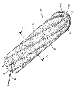
Fig. 1 illustrates a substantially cylindrical tam-
pon 30 for feminine hygiene, having an insertion end 32,
CA 02442271 2003-09-25
WO 02/076357 PCT/EP02/03263
14
a recovery end 34, a longitudinal section 36 lying there-
between, and a recovery tape 35. The tampon 30 consists
of a compressed, liquid-absorbing, tangled fibrous mate-
rial made of natural and/or synthetic fibers. The fibrous
material contains at least a certain quantity of fibers,
for example 25%, which have an irregular, for example
non-round or star-shaped, cross section and consequently
have a considerably increased memory effect, which in-
creases the absorption capacity of the tampon 30.
The tampon 30 is provided with a number of longitu-
dinal ribs 40, in the present case eight. The longitudi-
nal ribs 40 are curved spirally or helically in the axial
direction between the insertion end 32 and the recovery
end 34 and in each case extend over 120 of the tampon
circumference in the case of a diameter of the tampon 30
of 13 mm. However, the circumferential angle a can, de-
pending also on the dimensions of the tampon, be selected
in the range of up to at least 150 , when one-part press
jaws are used preferably in the range of 80 to 120 of
the tampon 30. The number of longitudinal ribs 40 can
vary, for example depending on the diameter of the tampon
and/or the type of absorption material, but should pref-
erably be an even number not less than four or six.
According to Fig. 2, the tampon 30 has a compressed,
central, solid, generally cylindrical fiber core 38 with
a high degree of compression, which ensures the stability
or bending resistance of the tampon 30 during digital
introduction of the tampon 30 into a body cavity. The
eight longitudinal ribs 40 are relatively uncompressed
and have, in particular on a circumferential surface 46
of the tampon 30, a soft fibrous structure. The longitu-
dinal ribs 40 extend radially outward at equal circumfer-
ential angle intervals from this solid fiber core 38. As
shown in Fig. 2, the spiral longitudinal ribs 40 are
separated from one another by eight correspondingly spi-
CA 02442271 2003-09-25
WO 02/076357 PCT/EP02/03263
ral longitudinal grooves 42 which are open radially to
the outside at least in the area of the compressed cylin-
drical fiber core 38. The longitudinal grooves 42 are
closed at least at the circumferential surface 46 of the
tampon 30 by virtue of the fact that side flanks 44 of
adjacent longitudinal ribs 40 touch one another essen-
tially only in the area of their radially outer ends and
form the soft, closed, approximately cylindrical circum-
ferential surface 46 of the tampon 30. This closed, soft
circumferential surface 46 of the tampon 30 makes possi-
ble more gentle and therefore more pleasant introduction
of the tampon 30 into the body cavity and a high absorp-
tion capacity of the same.
As a result of the fact that the outer ends lying
against one another of the side flanks 44 of adjacent
longitudinal ribs 40 close the longitudinal grooves 42
only at the circumferential surface 46 of the tampon 30,
the longitudinal grooves 42 form in each case eight
closed spiral guide ducts 50 (Fig. 2) which are in each
case preferably open only at the insertion end 32 and at
the recovery end 34 (the openings at the insertion end 32
are visible in Fig. 1). These guide ducts 50 each have a
drop-shaped cross section which is largest at the fiber
core 38 and tapers radially outwardly to the place in
which the adjacent longitudinal ribs 40 lie against one
another with the radially outer ends of their side flanks
44. Immediately after the introduction of the tampon 30
into the body cavity, these spiral guide ducts 50 convey
the body fluid to the fiber core 38 also, in order to
utilize its fibrous material immediately to increase the
absorption capacity and expansion capacity of the tampon
30 and to accelerate the opening of the closed guide
ducts 50 radially outwardly. Therefore, the arrangement
of the spiral longitudinal ribs 40 and the spiral guide
ducts 50 or longitudinal grooves 42 brings about an en-
largement of the surface of the tampon 30 and conse-
CA 02442271 2003-09-25
WO 02/076357 PCT/EP02/03263
16
quently an extension of the dwell time or absorption, time
for body fluid, which results in the absorption capacity
and expansion capacity of the fiber core 38 being im-
proved considerably. At the same time, a reduction in the
weight of fibrous material used in the tampon 30 is thus
possible, which allows more economical production of the
tampon 30.
The recovery end 34 of the tampon 30 is, as is known
per se, provided with a finger recess 48,' which facili-
tates the insertion of a finger to expand the recovery
end 34 and to subsequently introduce the tampon 30 and
accelerates the expansion of the tampon 30. For this
purpose, the insertion end 32 of the tampon 30 also has
a round dome 52, the outer edge of which is smoothed or
chamfered. As the approximately hemispherical dome 52 has
a relatively short length, the spiral longitudinal ribs
40 and spiral longitudinal grooves 42 can extend over an
optimum length of the tampon 30.
The tampon 30 has an approximately circular diameter
in the range from 6 to 17 mm, the compressed, approxi-
mately cylindrical fiber core 38 having a diameter of up
to 5 mm. The tampon-30-is,-preferably at least partially
surrounded by a liquid-permeable sheathing, which is
known per se and therefore not shown. This sheathing can
consist of, for example, an airlaid nonwoven covering
material made of tangled, at least in part thermoplastic,
heat-sealing fibers or of a perforated plastic film. In
particular when nonwoven covering material is used for
the tampon sheathing, it is recommended that the circum-
ferential surface 46 of the tampon 30 is smoothed, which
can, if appropriate, be carried out with the application
of heat. Such a sheathing improves the comfort of intro-
duction and prevents fibers being detached during intro-
duction or removal of the tampon 30 into or from the body
cavity. Finally, the tampon 30 can be more weakly radi-
ally pressed in the area of its recovery end 34, so that
CA 02442271 2003-09-25
WO 02/076357 PCT/EP02/03263
17
the fibrous material there is less strongly compressed
and the expansion of the fibrous material at the recovery
end 34 before introduction of the tampon 30 is made eas-
ier.
As Fig. 3 shows, an apparatus 60 for producing the
tampon 30 described above consists of a number of ele-
ments arranged "coaxially one behind another, namely a
feed and ejection device 62, a star-shaped press 64 with
press jaws 66 which have pressed a preform 84 in their
closed or pressing position, a final shaping tool 68 and
a circulating or rotating transport apparatus 70. The
transport apparatus 70 is, for example, a revolver 72, to
which transport sleeves 74 are fixed at equal circumfer-
ential angles and radii. The revolver 72 can be moved
step by step, so that the transport sleeves 74 can be
moved successively in front of the outlet end of the
final shaping tool 68 to receive in each case a finished
tampon 30 ejected from the final shaping tool 68 by the
device 62.
The feed and ejection device 62 according to Figs 3
and 10 is known per se and consists of a feed pusher 76
which can be moved to and fro coaxially with respect to
a press opening 78 of the press 64. The feed pusher 76
has a circular face 80 with a diameter which corresponds
approximately to that of a tampon blank 55 (Fig. 5),
preferably of a wound blank, by means of which face the
tampon blank 55 can be transferred coaxially into the
opened press 64. A bar-shaped ejector 82 is mounted dis-
placeably to and fro relative to the feed pusher 76 coax-
ially inside the feed pusher 76, the diameter of which
ejector is smaller than the press opening 78 in the
raised position of the press jaws 66. The ejector 82
serves for, in a single operation, transferring in each
case one preform 84 pressed in the press 64 through the
final shaping tool 68 into one of the transport sleeves
74 of the revolver 72. In the final shaping tool 68, the
CA 02442271 2003-09-25
WO 02/076357 PCT/EP02/03263
18
preform 84 then takes on the final shape of the finished
pressed tampon 30 described above.
Fig. 4 shows a cross section of the preform 84 in
Fig. 3. It can be seen that the cross section of the
longitudinal ribs 40 is widened radially outwardly in a
drop-shaped manner to the circumferential surface 46 of
the preform 84.'In contrast, the longitudinal grooves 42
extend radially inwardly in a cross-sectionally drop-
shaped manner to the fiber core 38, so that they are
wider at the foot of the longitudinal ribs 40 than in the
area of the circumferential surface 46 of the preform 84.
In other words, the distance between mutually opposite
side flanks 44 of adjacent longitudinal ribs 40 is
smaller at their radially outer ends remote from the
fiber core 38 than in the foot area of the longitudinal
ribs 40 or at the fiber core 38. Depending on the condi-
tions of use of a tampon, this cross section shown in
Fig. 4 with radially outwardly open longitudinal grooves
42 can also be a very suitable solution for the final
shape of a tampon, for example if high, immediate absorb-
ency of a tampon is to be the most important factor. If
appropriate, such a tampon provided with open longitudi-
nal grooves 42 can likewise be surrounded by a liquid-
permeable sheathing.
According to Figs 5 and 6, the press 64 consists of
eight identical press jaws 66 which are arranged in a
star formation in a common plane at equal angle intervals
about and at the same radial distance from the press axis
x. The preferably even number of press jaws 66 can vary,
for example depending on the weight and the composition
of the material intended for the tampon 30, and can also
be smaller or greater than eight, although the number
should not be under four. The press jaws 66 have the same
dimensions and can be moved to and fro synchronously
radially with respect to the press axis x between their
open position and closed position (see Fig. 5). In the
CA 02442271 2009-10-27
'77060-26
19
closed or pressing position, the press jaws 66 are in
each case supported on one another on their mutually
opposite side walls 86, 88, as is explained in greater
detail below.
Figs 5 and 6 show the inlet side of the press 64,
the press jaws 66 of which are illustrated in the opened
and in the closed position in Fig. 5. Each press jaw 66
has a jaw foot 108 with three through-holes 110 for fix-
ing elements (not illustrated) on guide strips (not il-
lustrated either).
The profile of the press jaws 66, which can be seen
in the front view of the press 64 in Figs 5 and 6, ex-
tends essentially on that side of a longitudinal mid-axis
y of each press jaw 66 which is oriented counterclock-
wise, in an L-shaped manner from the jaw foot 108 to the
press opening 78. The profile of each long L-leg 112 is
tapered radially in a triangle-like manner toward a short
L-leg 114 and, after this taper, merges at its radially
inner end into a striking head 116 (Fig. 5) which has a
rounded profile and is a component of the strengthened
short L-leg 114 which is angled in the clockwise direc-
tion as compared with the long L-leg 112. This angling is
in the-form of a striking recess 118, the round cross-
sectional profile of which extends over an arc of ap-
proximately 90 in the direction of the press opening 78
and corresponds to the cross-sectional profile of the
striking head 116 of the press jaw 66 adjacent in the
clockwise direction. The end of the short L-leg 114 lies
at a small distance from the press jaw axis y and forms
a pressing blade 92.
A longitudinal mid-axis z of the profile of the
pressing blade 92 forms with the longitudinal mid-axis y
of the associated press jaw 66 an acute angle a/2 which
in each case opens counterclockwise in relation to the
longitudinal mid-axis y of the press jaw 66. This acute
angle a/2 between the longitudinal mid-axis z of the
CA 02442271 2009-10-27
77060-26
pressing blade 92 and the longitudinal mid-axis y of the
press jaw 66 in Figs 5 and 6 corresponds to half the
circumferential angle a/2, that is to say 60 in the pres-
ent case, with which each longitudinal groove 42 extends
spirally over the circumferential angle of 120 about the
press axis x. It follows from this that the profile of
the other, rear end (not visible in Figs 5 and 6) of the
same press jaw 66 is curved in the clockwise direction as
compared with the front press jaw profile visible in Figs
5 and 6, or encloses an angle with.the longitudinal mid-
axis y of the press jaw 66 concerned which opens in the
clockwise direction in Figs 5 and 6 and corresponds to
the second half circumferential angle a/2 of 60 of the
overall circumferential angle a.of 120 .
In the long L-legs 112 of the press jaws 66, a blind
hole 111 is in each case arranged in the vicinity of the
pressing blade 92 for receiving a heating element. The
blind holes 111 are positioned in the best possible man-
ner in order to bring about optimum heating of each press
jaw 66. The temperature of the press jaws 66 is in the
range from 80 C to 120 C and is regulated by means of
electronic pulses while observing as small as possible a
tolerance range. Each press jaw 66 has its own tempera-
ture sensor. The thermal insulation of each press jaw 66
consists of a synthetic material made by the company
Ensinger GmbH, 71154 Nufringen, Germany, which is resis-
tant to high temperature and high pressure or compressive
force. By heating the press jaws 66, it is possible to
reduce the memory effect of modern, highly absorbent,
greatly expanding fibrous materials, which occurs after
the tampon 30 has been finished. By means of the heated
press jaws 66, the surface of the tampon 30 is simultane-
ously smoothed during pressing and pushing out, and a
qualitatively improved surface is produced even in tam-
pons of low weight, the stability of the tampon 30 being
CA 02442271 2009-10-27
77060-26
21
preserved. The memory effect of the fibrous material
becomes effective again when the fibrous material of the
tampon 30 is wetted with body fluid.
Figs 7 and 8 show more clearly that each press jaw
66 has an effective pressing surface 90 which is in each
case stepped. These pressing surfaces 90 form a press
opening 78 of round cross section with a length in the
range from 40 mm to 70 mm. Each pressing surface 90 has
a pressing blade 92 which is oriented toward the press
opening 78, and a pressing shoulder 96 which is arranged
only on a specific side flank 44 of the pressing blade
92, that is to say is in each case oriented in the same
circumferential direction about the press axis x. The
stepping is brought about by virtue of the pressing
shoulder 96 being offset to the outside in relation to
the press axis x with respect to a pressing edge 94 at
the free, inner end of the pressing blade 92. Further-
more, the area of the pressing shoulder 96 is greater
than that of the pressing edge 94 of the pressing blade
92 of each press jaw 66. At the same time, the pressing
surface 90 in each case consisting of the pressing blade
92 and the pressing shoulder 96 on each press jaw 66 is
spirally shaped. The pressing blade 92 and the associated
pressing shoulder 96 of each press jaw 66 can extend over
a circumferential angle a of up to at least 150 in the
closed or pressing position of the press 64, with a di-
ameter of the press opening 78 in the range from 8 to
17 mm. For the press jaws 66 of the present illustrative
embodiment, which are formed in one part, a circumferen-
tial angle a of the pressing blade 92 and of the pressing
shoulder 96 of each press jaw 66 of 80 to 150 , 120 in
the present case, is preferred.
According to an important feature of the present in-
vention, provision is made that the press jaws 66, when
in a pressing position d in Fig. 9, touch an imaginary
barrel-shaped envelope surface 104 with their substan-
CA 02442271 2003-09-25
WO 02/076357 PCT/EP02/03263
22
tially spiral pressing surface 90. In the pressing posi-
tion, the pressing blade 92 of each press jaw-66 is ori-
ented essentially although not exactly radially with
respect to the press axis x (Figs 5 and 6) . The spiral
pressing blades 92 and spiral pressing shoulders 96 of
all the press jaws 66, when in a clearance position d+ in
Fig. 10, each touch an imaginary, substantially circu-
larly cylindrical envelope surface 106. In this connec-
tion, the diameter of the cylindrical envelope surface
106 of the clearance dimension d+ of the press jaws 66
corresponds at least to the greatest diameter of the
barrel-shaped envelope surface 104 of the pressing dimen-
sion d of the press jaws 66. Moreover, provision is made
that the 0 vertex of the arcuate curvature 102 of the
spiral pressing surface 90 lies on the longitudinal
mid-axis y of each press jaw 66, the pressing' surface 90
extending toward its two ends in complementary fashion in
each case over half a circumferential angle a/2 in the
range of up to at least 75 of the spiral pressing surface
90 of the press jaw 66. This situation is explained in
greater detail below.
The cross section of the pressing blade 92 is drop-
shaped, the greatest thickening lying behind the front,
narrow, rounded pressing edge 94, and a neck-like con-
traction 122 being present toward a pressing blade foot
95. The pressing shoulder 96 is arranged eccentrically
with respect to the pressing blade 92, in each case only
on one specific side surface of two side surfaces 98, 100
of the pressing blade 92 (Fig. 7) . This specific side
surface 98 or 100 of all the press jaws 66, which adjoins
the pressing shoulder 96, is in each case uniformly ori-
ented only, in the clockwise direction or counterclock-
wise. In Figs 5 and 6, which show the front side of the
press 64, this side surface 98 of the pressing blade 92
facing toward the pressing shoulder 96 is in each case
oriented counterclockwise. In this connection, each
CA 02442271 2003-09-25
WO 02/076357 PCT/EP02/03263
23
pressing shoulder 96 is offset to the outside radially in
relation to the press axis x with respect to the narrow
pressing edge 94 of the pressing blade 92 by the radial
distance between the fiber core 38 and the circumferen-
tial surface 46 of the preform 84, and has in the circum-
ferential direction of the press opening 78 a greater
area than the pressing edge 94 of the pressing blade 92.
The center of curvature of the pressing shoulders 96 of
all the press jaws 66 then lies on the axis x of the
press 64 only in the clearance position d+ of the press
jaws 66.
According to Figs 7 and 8, which show the end face
of a press jaw 66 at the rear or outlet side of the press
64, the pressing shoulder 96 is, in contrast, oriented in
the clockwise direction. The pressing surface 90, con-
sisting of the pressing blade 92 and the pressing shoul-
der 96, of each press jaw 66 runs spirally with respect
to the press axis x of the press opening 78. In this
connection, the pressing blade 92 and, the associated
pressing shoulder 96 of each press jaw 66 extend over a
circumferential angle of 120 of the pressed preform 84
between the two ends of the same. Half the circumferen-
tial angle a/2 extends in each case over 60 in the pres-
ent case in a symmetrical or complementary fashion on
both sides of the longitudinal mid-axis y of each press
jaw 66, so that the press jaw 66 is loaded uniformly over
its entire cross section by the pressing forces exerted.
As mentioned, the circumferential angle a can generally,
however, for example depending on the length and/or the
final diameter of the finished tampon, which is 13 mm in
the present illustrative embodiment, be up to at least
150 , preferably from 80 to 120 , in the case of one-part
press jaws.
The pressing blades 92 and pressing shoulders 96 of
each press jaw 66 are not only curved spirally in the
CA 02442271 2003-09-25
WO 02/076357 PCT/EP02/03263
24
longitudinal direction corresponding to the described
circumferential angle a of the tampon 30 of 120 , but also
have a curvature 102 (Figs 8 and 9) from one end of the
press jaw 66 to the other end of the same press jaw 66.
This curvature 102 ensues from the fact that the effec-
tive pressing surface 90 of each press jaw 66 has to
press a spiral longitudinal groove 42 which must in each
case extend over a specific circumferential angle of the
preform 84, that is to say in the present cas.e over 120
of the circumferential surface of the approximately cy-
lindrical tampon blank 55 at a specific angle of inclina-
tion 0 (Fig. 1). In this connection, the tampon blank 55
(Fig. 5) is as a whole compressed to the pressing dimen-
sion d of the preform 84 (Fig. 9), at which each pressing
blade 92 is moved beyond the position which is radial
with respect to the press axis x. As a result, the clear
cross section of the press opening 78 formed by the press
jaws 66 widens from both its ends to the longitudinal
center of the press jaws 66 or of the press opening 78
formed by these, which consequently assumes a barrel
shape in the pressing dimension d or in its pressing
position. The_en:velope 'surface 104 touching the pressing
blades 92 or the pressing shoulders 96 therefore has a
slightly barrel-like contour (see Figs 3 and 9) which
therefore narrows toward both ends of the press opening
78. Accordingly, the preform 84 also assumes a corre-
sponding shape in the press 64, as can be seen from Figs
3 and 9. In order that the preform 84 can be ejected
perfectly, that is to say without damage to the fibrous
structure on its surface, from the press 64 while being
rotated about its longitudinal axis, the press jaws 66
have to be raised by a specific dimension d+ (Fig. 10).
This clearance dimension d+ corresponds at least to the
radial distance which separates a chord A, which inter-
connects the two ends of the pressing blade 92 of a press
jaw 66 in Fig. 9 and runs parallel to the press opening
CA 02442271 2003-09-25
WO 02/076357 PCT/EP02/03263
78, from a tangent B in Fig. 9, which is placed against
a vertex 00 of the radially outwardly arcuate curvature
102 of a pressing blade 92 and is likewise oriented par-
allel to the press opening 78. In addition, the clearance
dimension d+ can be defined in such a way that it must
correspond at least to the greatest diameter of the bar-
rel-shaped envelope surface 104, which is touched by the
pressing blades 92 or pressing shoulders 96 in the press-
ing position. In the case of a tampon 30 with a diameter
of 13 mm, this clearance dimension = d + 0.6 mm, by which
the press jaws 66 must be moved radially outwardly in
order to form, according to Fig. 10, the circularly cy-
lindrical envelope surface 106 of the press opening 78.
In this connection, the pressing blades 92 or pressing
shoulders 96 touch the circularly cylindrical envelope
surface 106 spirally over essentially the entire length
in the clearance dimension d+ and consequently form a
circularly cylindrical press opening 78 for the ejection
of the preform 84.
Figs 5 and 6 show clearly that the neck-shaped con-
traction 122 of each pressing blade 92 brought about by
the drop shape makes possible a greater displacement of
the fibrous material approximately radially outwardly
during pressing. As a result, the pressing dimension of
the press jaws 66 can be reduced to, for example, 4 mm
from previously 4.8 mm of the diameter of the fiber core
38 with the same stability and improved absorption capac-
ity and with the soft surface of the tampon 30 being
preserved. Furthermore, the width of the rounded pressing
edge 94 can be reduced, in order to make it possible for
the fibrous material to flow into the radially outwardly
created free space of the press opening 78. In this way,
the quantity of fiber necessary for producing the fiber
core 38 can be reduced in favor of that quantity of fiber
which, with the same stability of the tampon, is avail-
CA 02442271 2003-09-25
WO 02/076357 PCT/EP02/03263
26
able for immediate liquid absorption after introduction
of the tampon into the body cavity.
In order to be capable of receiving the outwardly
displaced fibrous material, the pressing shoulder 96 has
a reduced shoulder radius of 6.2 mm in the present illus-
trative embodiment, compared with 6.55 mm previously, and
extends in profile approximately parallel to that side of
the press jaw 66 oriented counterclockwise, which merges
into the short L-leg 114 and forms the striking head 116.
The outward displacement of the fibrous material
achieved by means of this shape of the press jaws 66
makes possible a saving of fibrous material which, in the
illustrative embodiment described of a digital tampon 30
with a final diameter of 13 mm and a length of 50 mm,
requires the use of only 2.4 g of fibrous material as
against 2.7 g 'of fibrous material previously. In this
connection, the fibrous material is composed of 75%
highly expansive fibers of irregular, for example star-
shaped, cross section and 25% cotton fibers.
It can be seen in particular from Figs 7 and 8 that
at least one squeezing rib 120 is provided on an outer
side of the pressing shoulder 96 approximately at the
level of the latter. In the closed state (pressing dimen-
sion d) of the press 64, this squeezing rib 120 of the
pressing shoulder 96 and also the striking head 116 of
each press jaw 66 bear against the rounded striking re-
cess 118 of the adjacent press jaw 66 in front of the
neck-shaped contraction 122 of the pressing blade 92
(Figs 5 and 6). The outer side of each pressing shoulder
96 is provided in Figs 7 and 8 with two parallel squeez-
ing ribs 120 which close a gap 124 oriented approximately
radially with respect to the press axis x between the
striking head 116 and the striking recess 118 of adjacent
press jaws 66 in relation to the press opening 78 and
thus in each case in relation to the radially outer side
of a spiral longitudinal rib 40 of the preform 84. As a
CA 02442271 2003-09-25
WO 02/076357 PCT/EP02/03263
27
result, the penetration of fibrous material of the tampon
blank 55 into the gap 124 between adjacent press jaws 66
is essentially precluded. In the event that fibers pene-
trate the gap 124 between adjacent press jaws 66, the
squeezing ribs 120 cut the staple length of these fibers,
so that the fiber residues can fall out of the press 64
and be extracted by suction. A burr-free, smooth, soft,
radially outer surface of each spiral longitudinal rib 40
is consequently formed.
Figs 7 and 8 show clearly that at one end face the
striking head 116 protrudes further radially inwardly
than the pressing blade 92 which is set back by the width
of the pressing shoulder 96 with respect to the striking
head 116 and is angled in relation to the latter toward
the side facing away from the striking head 116. By means
of the side walls 86, 88, the press jaws 66 have a cross
section normal to their longitudinal mid-axis y which has
a shape which is complementary to the circumferential
angle a of the spiral press jaw curvature 102, so that
the abovementioned uniform distribution of the pressing
forces exerted in each case by the press jaws 66 over
their entire cross section, that is to say in the direc-
tion of the longitudinal mid-axis y of the press jaws 66,
is guaranteed.
Fig. 9 illustrates the pressing dimension d of the
press 64 diagrammatically. This pressing dimension d
corresponds to the barrel-shaped envelope surface 104
which is formed by the spiral pressing blades 92 and
pressing shoulders 96 of the press jaws 66 of the press
64 in the closed state or pressing dimension d. This
pressing dimension d is, depending on the particular
composition and purpose of the tampon 30 concerned, be-
tween 6 and 17 mm, 13 mm in the present illustrative
embodiment, at the inlet end and at the outlet end of the
closed press 64.
CA 02442271 2003-09-25
WO 02/076357 PCT/EP02/03263
28
During ejection of the preform 84 from the press 64
in this pressing position shown in Fig. 9, the ejection
forces would increase greatly as a result of the barrel-
shaped cross section of the press opening 78 and of the
preform 84 situated therein. The fibers on the surface of
the preform 84 would be torn out of the fiber composite,
the smooth surface of the preform 84 would be correspond-
ingly damaged and a fiber loss would be caused. For this
reason, provision is made that, after the opening of the
press 64 to the given clearance dimension d+,'the imagi-
nary envelope surface 106 formed or touched by the press-
ing blades 92 or the pressing shoulders 96 is circularly
cylindrical, so that the preform 84 can be ejected from
the press 64, virtually without any appreciable resis-
tance, through the final shaping tool 68 into the trans-
port sleeve 74 with simultaneous rotation as a result of
the spiral pressing blades 92 engaging in the longitudi-
nal grooves 42 of the preform 84.
In Fig. 10, the spiral pressing blades 92 and press-
ing shoulders 96 of the press jaws 66 have been moved
back radially outwardly by a given clearance dimension d+
of, in the present illustrative embodiment, d + 0.6 mm in
relation to the pressing dimension d shown in Fig. 9, in
order to enclose or touch the imaginary circularly cylin-
drical envelope surface 106, which allows the preform 84,
which has been pressed in a barrel shape and provided
with spiral longitudinal ribs 40 and longitudinal grooves
42, to be pushed out of the press 64 virtually without
friction by means of the ejector 82 in the feed pusher
76.
According to Fig. 10, the pressing blades 92 and the
pressing shoulders 96 of all the press jaws 66 therefore
each touch the imaginary, circularly cylindrical envelope
surface 106 on a spiral line over at least a considerable
part of their length. That is to say if a lower degree of
compression of the fibrous material is desired at the
CA 02442271 2003-09-25
WO 02/076357 PCT/EP02/03263
29
recovery end 34 of the preform 84, the radial distance of
the effective pressing edges 94 from the press axis x in
the area of the outlet side 79 of the press opening 78 is
dimensioned to be somewhat greater, in the closed state
of the press jaws 66, than over the remaining longitudi-
nal area of the pressing edges 94, so that this part of
the pressing edges 94 would not touch the circularly
cylindrical envelope surface 106 in the clearance dimen-
sion d+ of the press jaws 66 but would lie slightly radi-
ally outside this circularly cylindrical envelope surface
106.
Figs 11 and 12 show an embodiment of a press 130
with multi-part press jaws 132. The divided press jaws
132 can be moved to and fro radially with respect to the
press axis x independently of one another. The press jaws
132 are divided in at least one plane T which is oriented
at right angles to the press axis x. In the present il-
lustrative embodiment, the press jaws 132 are of two-part
design. The dividing plane T of the two-part press jaws
132a, 132b intersects the 0 vertex of their pressing
surface 134 and the axis x of the press 130, at the lon-
gitudinal center M of the same. The press-jaw halves 132a
associated with the outlet side 79 of the press 130 can
be moved radially outward into the clearance position d+
from their pressing position d in relation to the press
axis x in order to make possible essentially friction-
free ejection of the preform 84 from the press. (Fig. 12).
By multiple division of the press jaws 132 transversely
to the press axis x and depending on the number of press
jaws 132, the circumferential angle a can be extended
beyond 150 . Furthermore, suitable design of the press
jaws also makes it possible to modify the outer contour
of the tampon depending on the specific tampon require-
ments.
From the above description of the press jaws 66; 132
according to the invention, it can be stated in summary
CA 02442271 2003-09-25
WO 02/076357 PCT/EP02/03263
that the press jaws have to lie diametrically opposite
one another in pairs. The present invention also includes
the possibility of, in addition to the press jaws 66; 132
described, which produce the fiber core 38, building
press jaws into the press 64; 130 which serve purposes
other than the production of the fiber core 38. Accord-
ingly, it is possible to use press jaws within the press
64; 130 in order, for example, to stamp patterns or de-
pressions onto or into the surface of the tampon 30 dur-
ing pressing of the preform 84, which are intended to
serve decorative and/or physical purposes.
Figs 13, 14 and 15 show the final shaping tool 68,
which consists of a guide plate 140 which is arranged in
a stationary manner immediately behind and coaxially with
the press 64 and is designed in one piece with a smooth-
ing bush 150 for the preforms 84. The final shaping tool
68 includes a conical final shaping channel 152 for the
preforms 84, which extends through the guide plate 140
and the smoothing bush 150. As shown in Fig. 3, the guide
plate 140 is arranged immediately in front of the outlet
side 79 of the press 64 and, as already described in US
Patent 5,911,712, is provided on its side facing the
press 64 with a number of grooves 142 corresponding to
the number of press jaws 66; 132, which are arranged at
the same circumferential angle intervals as the press
jaws 66; 132. According to the invention, the grooves 142
extend at a distance from and parallel to the press jaw
axis y in the direction of the press opening 78 tangen-
tially with respect to the final shaping channel 152.
It can be seen from Figs 3 and 7 to 12 that the
press jaws 66; 132 are each provided at their rear end
with a positioning web 160 which projects with respect to
the outlet side 79 of the press 64 and in each case en-
gages in one of these grooves 142 with lateral play. The
inner, free front end of the positioning webs 160 is a
component of the pressing surface 90; 134 of the press
CA 02442271 2003-09-25
WO 02/076357 PCT/EP02/03263
31
jaws 66; 132 and reaches over an axial gap between the
press 64; 130 and the final shaping tool 68. In their
clearance position d+, the pressing surfaces 90; 134 of
the press jaws 66; 132 have a slightly smaller diameter
than the inlet opening 154 of the smoothing bush 150 in
order that the recovery tape 35, which has previously
already been wound spirally at the recovery end 34 of the
tampon blank 55 lying at the front in the transport di-
rection x (Figs 14, 15), maintains its centered position
at the recovery end 34 by virtue of the positioning webs
160 during pressing and ejection of the tampon 30 from
the press 64. From the circular inlet opening 154, the
final shaping channel 152 tapers conically to an outlet
opening 156 of the smoothing bush 150. In this connec-
tion, the conical shape of the smoothing bush 150 is
designed in such a manner that as small as possible an
ejection force is necessary in order to push the preform
84 out of the press 64 through the smoothing bush 150 and
to compress it concentrically to the final dimension of
the tampon 30.
Figs 3 and 12 to 14 show that the final shaping tool
68 is provided with spirally shaped, radially inwardly
projecting smoothing ribs 170, the number of which corre-
sponds to that of the press jaws 66 and the angle of
inclination 0 of which corresponds to that of the spiral
pressing blades 92. The spiral smoothing ribs 170 engage
directly in a lightly concentrically pressing and smooth-
ing manner in the spiral longitudinal grooves 42 of the
preform 84 leaving the press 64, so that the profile of
the preform 84 is preserved but the widening of the cross
section of the fiber core 38 caused by the barrel shape
of the preform 84 is reduced. The smoothing bush 150 can
be heated to a temperature of 80 to 120 C in order, if
desired, to optimize the smoothing effect. The smoothing
ribs 170 end at a distance in front of the outlet opening
156 of the smoothing bush 150 and merge into a smooth
CA 02442271 2003-09-25
WO 02/076357 PCT/EP02/03263
32
cylindrical end section 172 of the smoothing bush 150.
This end section 172 of the smoothing bush 150 has a
diameter which corresponds to the diameter of the fin-
ished pressed tampon 30. In this smooth cylindrical end
section 172 of the smoothing bush 150, the spiral longi-
tudinal grooves 42 of the preform 84, which were open up
to here, are closed at the radially outer ends of the
side flanks 44 of adjacent spiral longitudinal ribs 40 to
the final diameter of the tampon 30 (Fig. 2) . In this
way, the longitudinal grooves 42 become the liquid guide
ducts 50 which are preferably open toward both ends of
the tampon 30 (Figs 1 and 2).
In Figs 3, 12 and 13, the transport apparatus 70 is
illustrated in an essentially cut-away manner and con-
sists in the present case, as part of a circulating or
rotating transport system, of a revolver 72. The revolver
72 is provided with a transverse hole 148, in which the
cylindrical transport sleeve 74 fits and is fixed at
right angles to the circulating plane of the revolver 72.
The transport sleeves 74 are fixed to the revolver 72 at
equal circumferential angle intervals and radii, so that
in each case one transport sleeve 74 can be moved succes-
sively step by step in front of the outlet opening 156 of
the smoothing bush 150, in order to feed a finished
pressed tampon 30 to a further production station. In
this production station (not shown), as is known per se,
the insertion end 32 can be provided with the round dome
52 at the same time as the recovery end 34 is provided
with the finger recess 48.
As the tampon 30 is subjected to rotation by the
spiral press jaws 66 and the spiral smoothing ribs 170 in
one single operation on ejection from the press 64
through the smoothing bush 150 into the transport sleeve
74, the cylindrical transport sleeve 74, which is widened
conically over a short length at its inlet opening, en-
sures that the high quality of the surface and of the
CA 02442271 2003-09-25
WO 02/076357 PCT/EP02/03263
33
fibrous structure of the tampon 30 is preserved. In this
connection, this delayed laying of the tampon 30 against
the cylindrical inner wall of the transport sleeve 74 is
caused by the expansion of the fibrous material of the
finished pressed tampon 30, that is to say that the di-
ameter of the transport sleeve 74 is dimensioned to be
correspondingly greater so as to allow for this expansion
of the fibrous material of the tampon 30 immediately
after pressing. This is because a positive contact of the
tampon 30 against the cylindrical smooth inner wall of
the transport sleeve 74 takes place only, as a result of
its expansion after pressing, when the tampon 30 con-
cerned has, with its recovery end 34 lying at the front,
almost or completely left the outlet opening 156 of the
smoothing bush 150.
Furthermore, it can be seen in Fig. 14 that the out-
let-side spiral pressing edges 94 of the press jaws 66,
which edges lie opposite one another in pairs, form an
acute angle which widens to the outlet end 79 of the
press 64. As a result, the fiber core 38 is more weakly
pressed at the recovery end 34 of the preform 84, so that
the fibrous material can be spread slightly before use so
as to facilitate digital introduction of the tampon.
In Fig. 15, the incipient expansion of the tampon 30
and its resulting contact against the cylindrical inner
wall of the transport sleeve 74 at F is shown especially
clearly owing to the enlarged illustration. The fact that
the tampon 30 expands only once it is in the transport
sleeve 74 on account of the memory effect of the greatly
expanding fiber proportion, can be attributed to the high
production speed of the tampon. Associated with this is
the considerable advantage that the rotary movement to
which the tampon 30 is subjected during ejection encoun-
ters no appreciable resistance, so that the spiral fi-
brous structure of the tampon achieved by the invention
is preserved in its full extent.
CA 02442271 2003-09-25
WO 02/076357 PCT/EP02/03263
34
The method of producing the tampon 30 described
above comprises, as is known from US Patent 5, 832, 576,
the provision of a strip-shaped tangled-fiber nonwoven,
the width of which preferably corresponds approximately
to the length of the tampon 30, the separation of a
length from the tangled-fiber nonwoven, which is wrapped
around with a recovery tape 35, and then the winding up
of the length on itself to form an essentially cylindri-
cal tampon blank or wound blank 55. Before winding up, a
liquid-permeable layer is applied at least in places to
that outer side of the fibrous nonwoven strip which lies
on the outside during the manufacture of the tampon blank
55, which layer is fixed at least in places on the outer
side of the fibrous nonwoven strip section, preferably by
heat sealing. At least one nonwoven layer or a thermo-
plastic, heat-sealable perforated plastic film can be
used, which at least partly sheaths the circumferential
surface of the tampon 30, hydrophobic finishing of the
sheathing material being preferred.
The preferably cylindrical tampon blank 55, the re-
covery end 34 of which lies at the front in the feed
direction or in the direction of the press axis x, is
then introduced coaxially into the press 64 by means of
the feed pusher 76. Subsequently, the tampon blank 55 is
radially compressed by the press jaws 66 in the press 64
in each case over identical, narrow, spirally shaped
sections of identical angle of inclination 0 of its cir-
cumferential surface, which sections are separated from
one another by equal circumferential angles. In this way,
a preform 84 of barrel-shaped contour is produced, with
spirally running longitudinal grooves 42 on a solid fiber
core 38 with a high degree of compression which is sub-
stantially cylindrical but, because of the barrel shape,
is widened in cross section at mid-length, and with lon-
gitudinal ribs, 40 which extend radially outwardly from
the fiber core 38 and run spirally in the longitudinal
CA 02442271 2003-09-25
WO 02/076357 PCT/EP02/03263
direction of the preform 84. In this connection, the
spirally shaped sections are in each case pressed over a
circumferential angle _ of up to at least 150 , preferably
over an angle of 80 to 120 , in the present case over an
angle of 120 . In the press 64, the fibrous material is
preferably subjected to lower radial compressing pressure
in the area of the recovery end 34 of the tampon blank 55
than the remaining fibrous material of the tampon blank
55. The tampon blank 55 is, depending on the properties
of the fibrous material used, in particular in the event
of use being made of highly expansive fibers of irregular
cross section with a strong memory effect, pressed at a
temperature of the press jaws 66 of 80 to 120 C to the
final shape of the tampon 30, in order to achieve the
desired dimensional stability of the fibrous material by
eliminating the memory effect of the fibers, which imme-
diately becomes effective again on contact with bodily
fluid and thus increases the expansion and absorption
speed of the tampon 30 with the least possible use of
fibrous material.
In the press 64; 130, the tampon blank 55 is com-
pressed in a single pressing operation to form the bar-
rel-shaped preform 84 which, on ejection -from the press
64, is at the same time subjected to final shaping in the
downstream, if appropriate heatable, smoothing bush 150.
This final shaping consists in a weak radial pressure
being exerted on the outer ends of the spiral longitudi-
nal ribs 40 and on the spiral longitudinal grooves 42 by
the smoothing bush 150, which can be heated to 80 C to
120 C if so desired, and its smoothing ribs 170. This weak
radial pressure has the effect that the outer ends of the
mutually opposite side flanks 44 of adjacent longitudinal
ribs 40 are pressed against one another by the smooth,
circular cross section of the final shaping channel 152
in the area of the outlet opening 156 of the smoothing
CA 02442271 2003-09-25
WO 02/076357 PCT/EP02/03263
36
bush 150, so that the longitudinal grooves 42 and thus
the outer, approximately cylindrical, soft, closed cir-
cumferential surface 46 of the tampon 30 are shaped, and
the spiral liquid guide ducts 50 are produced in the area
of the now radially outwardly closed longitudinal grooves
42. Furthermore, the smoothing ribs 170 reduce slightly
the cross-sectional widening of the fiber core 38 caused
by the barrel shape of the preform 84 without the advan-
tage of the rapid liquid absorption and the associated
expansion capacity of the variable cross section caused
by the barrel shape suffering over the length of the
fiber core 38.
On the exit, associated with the rotary movement, of
the finished pressed tampon 30 from the smoothing bush
150 into the transport sleeve 74 of the transport appara-
tus 70, the newly compressed fibrous material expands in
relation to the very smooth, cylindrical inner wall of
the transport sleeve 74, without frictional resistance,
which would impair the surface quality, occurring between
the cylindrical, smooth inner wall of the transport
sleeve 74 and the fibrous material on the surface of the
tampon 30, so that the high quality of this tampon. 30
provided with spiral longitudinal ribs 40 and longitudi-
nal grooves 42 is ensured even in the case of mass pro-
duction. In this connection, it is important that the
direction of rotation, in which the length of a fibrous
nonwoven, at the end of which a sheathing material is
fixed on the outside, is wound up to form a tampon blank
55, is also maintained by the spiral press jaws and
smoothing ribs, in order that the embedding of the free,
outer end of the sheathing material strip in the surface
of the tampon 30 is maintained.
The above description of the invention shows that a
dimensionally stable tampon for feminine hygiene with a
surface which is enlarged by spiral longitudinal ribs and
longitudinal grooves is available, which can be produced
CA 02442271 2003-09-25
WO 02/076357 PCT/EP02/03263
37
at least partly from modern fibers which have a strong
memory effect and make possible a saving of fibrous mate-
rial while the absorption capacity is at least the same.
CA 02442271 2003-09-25
WO 02/076357 PCT/EP02/03263
38
List of reference numbers
30 tampon
32 insertion end
34 recovery end
35 recovery tape
36 longitudinal section
38 fiber core
40 longitudinal ribs
42 longitudinal grooves
44 side flanks
46 circumferential surface
48 finger recess
50 guide ducts
52 round dome
55 tampon blank
60 apparatus
62 feed and ejection device
64 press
65 end L-shaped press jaw profile
66 press jaw
68 final shaping tool
70 transport apparatus
72 revolver
74 transport sleeves
75 inlet opening (transport sleeve)
76 feed pusher
78 press opening
79 outlet side (press opening)
80 circular face
82 ejector
84 preform
86, 88 side walls of the press jaws
90 effective pressing surface
92 pressing blade
CA 02442271 2003-09-25
WO 02/076357 PCT/EP02/03263
39
94 pressing edge
95 pressing blade foot
96 pressing shoulder
98, 100 side surfaces of the pressing blade
102 curvature
104 barrel-shaped envelope surface
106 circularly cylindrical envelope surface
108 jaw foot
110 holes
111 blind hole
112 long L-profile leg
114 short L-profile leg
116 striking head
118 striking recess
120 squeezing rib
122 neck-like contraction
124 gap
130 press
132 press jaws
132a, 132b press jaw halves
134 pressing surface
140 guide plate
142 grooves
144 transverse hole
150 smoothing bush
152 final shaping channel
154 passage opening
156 outlet opening
160 positioning web
170 spiral smoothing ribs
172 end section (smoothing bush)
d pressing position, pressing dimension
CA 02442271 2003-09-25
WO 02/076357 PCT/EP02/03263
d+ clearance position, clearance dimension
x press axis
y longitudinal mid-axis (press jaw 66)
z longitudinal mid-plane (pressing blade 92)
T dividing plane
M longitudinal center
a circumferential angle
a/2 half circumferential angle
(3 angle of inclination
A chord
B tangent
F contact point
Z detail