Language selection

Search

Patent 2442513 Summary

Third-party information liability

Some of the information on this Web page has been provided by external sources. The Government of Canada is not responsible for the accuracy, reliability or currency of the information supplied by external sources. Users wishing to rely upon this information should consult directly with the source of the information. Content provided by external sources is not subject to official languages, privacy and accessibility requirements.

Claims and Abstract availability

Any discrepancies in the text and image of the Claims and Abstract are due to differing posting times. Text of the Claims and Abstract are posted:

  • At the time the application is open to public inspection;
  • At the time of issue of the patent (grant).
(12) Patent Application: (11) CA 2442513
(54) English Title: AMALGAM SEPARATOR
(54) French Title: SEPARATEUR D'AMALGAME
Status: Dead
Bibliographic Data
Abstracts

English Abstract


An amalgam separation and collection apparatus for the collecting and
separation of amalgam in a dental vacuum waste stream. The apparatus has
four primary chambers. The separation chamber is the connection point for the
incoming waste flow and once the waste flow has entered the apparatus, the
separation chamber allows the division of waste stream into vacuum air and
water particle amalgam. The vacuum air is permitted to flow through the unit
via
vacuum exhaust tube and is unobstructed. The water/amalgam mixture is
deposited from the separation chamber into the sedimentation chamber.
Separation by sedimentation occurs in this chamber causing the larger amalgam
particles to settle to the container base while the cleaner water raises and
water
falls under gravity into the filtration chamber. The wastewater with trace
amalgam passes through a heavy metal removal bed in the filtration chamber.
The purified amalgam free water collects in water re-entrainment chamber
located of the base of the filtration chamber. The collected water is
introduced to
the vacuum air via an orifice in the vacuum exhaust tubing. A tube is
connected
to dental office vacuum pump permitting function. The amalgam waste is
retained in two removable chambers namely the sedimentation and filtration
chambers.


Claims

Note: Claims are shown in the official language in which they were submitted.


I claim

1. An amalgam collection and separation apparatus used to collect and
purify the total mixture of liquid and solid particles found in a dental
vacuum
stream comprising of:
- a container having a lid which incorporates a chamber to allow separation of
liquid and air in the waste stream and has interconnection orifice. A
sedimentation chamber which allows the settling of heavy particles in the
liquid
waste stream. A filtration chamber which incorporates a media bed for the
removal of fine and dissolved particles in the liquid waste stream. The
filtration
chamber also incorporates a water re-entrained area at its base for the
reintroduction of purified wastewater to the vacuum air stream.
A body which incorporates a vacuum air exit pipe which permit the flow of
vacuum air through the unit and re-entrainment of vacuum air and water prior
to
exiting the apparatus.
2. The apparatus of claim 1 where the container has a lid portion which
houses the inlet, a body portion comprising the mid section, a sedimentation
container which mounts to the body at the bottom and a filtration container
which
also mounts to the body at the bottom and has an outlet connection.
3. Apparatus as in Claim 1 where the containers are manufactured by
rotational molding.
4. An apparatus in Claim 1 where the lid is removable.
5. Apparatus as in Claim 1 where the apparatus has no moving internal


parts.
6. An apparatus in Claim 2 where the lid also function to separate liquid and
gas streams through functioning as a separation chamber.
7. An apparatus in Claim 2 where the lid has an extended portion used to
direct the liquid and particle waste into the unit bottom containers.
8. An apparatus in Claim 1 where the containers mounted to the body at the
bottom are removable.
9 An apparatus as outlined in Claim 1 where one of the containers is used
for the collection of large particle waste thus acting as a sedimentation
chamber.
An apparatus as in Claim 1 where one container is used to hold a media
bed thus acting as a filtration chamber.
11 An apparatus in Claim 1 where the media bed is activated carbon.
12. An apparatus as in Claim 8 where the base of the filtration container also
functions as a purified water re-entrainment chamber whereby water can be re-
introduced to the vacuum stream.
13. The apparatus of Claim 1 further incorporate a tongue and grove housing
an o-ring seal which connects the lid sedimentation containers and filtration
containers to the body forming a liquid tight seal.
14. The apparatus in Claim 1 where the individual container which function as
chambers are connected together using a mechanical device designed to
compress the o-ring resulting in a liquid tight seal.
15. A method of collecting and separating a mixture of particles and liquid
from a patient under going a dental procedure the method of collection,
separation and purification comprising the following steps:
Connection of the a collection apparatus to a vacuum source. The apparatus
has an inlet which connects the apparatus to the patient via a tube. The
apparatus has five primary parts: 1) lid which functions as a separation
chamber; 2) body which houses the vacuum air exit pipe and to which all other
components are attached; 3) collection container which function as a
sedimentation chamber; 4) a filtration chamber which contains activated carbon
and has a liquid containment area at its base.
Solid particles and liquid are drawn from the patient into the separation
chamber
where vacuum air or gas is separated from liquid and particles.

5


Liquid and particles flow down an extended portion of the separation chamber
and collects in the sedimentation chamber.
The separated vacuum air flows down the exit pipe and connects to the vacuum
pump.
The collected liquid in the sedimentation chamber water falls into the
filtration
chamber and flows through a media bed. This is performed by gravity.
The purified liquid collects in a re-entrainment zone at the base of the
filtration
zone.
The purified liquid is re-entrained with the vacuum air via a small orifice
located
in the exit pipe within the re-entrainment zone.
16. An apparatus as in Claim 2 where separation chamber can one or more
inlet connections.
17. The apparatus of Claim 2 has removable sedimentation and filtration
chambers.
18. The apparatus in Claim 2 where the removable sedimentation and
filtration chambers may act as shipping containers for the purpose of
collection,
shipping, disposal and/or recycling.
19. The apparatus in Claim 2 where the outlet is located at the bottom of the
filtration container.

6


Description

Note: Descriptions are shown in the official language in which they were submitted.


CA 02442513 2003-09-23
~eSCriptlOn
Technical Field and Backgrcaund
The present invention is a dental apparatus which is for the collecting of
solid
material from a vacuum line which is commonly used to remove solid and liquid
from a patient's oral cavity during a procedure. The mixture of air, solids
and
liquid located in the vacuum fine contains a high percentage of heavy metals
primarily mercury, lead and copper. The untreated disposal of heavy metals
offers a possible source of environmental pollution.
Various devices have been attempted to separate amaigarn solids from liquid
waste stream with limited success. This is primarily due to the difficulties
in
several areas: 1) removaP of dissolved heavy metal such as mercury; 2)
difficulty
in service thus resulting in costly specialized personnel; 3) difficulty in
removal of
the amalgam or waste from the separator; ~) difficulty in transportation of
waste
far the purpose of disposal or recycling; 5) high cost due to material choices
for
the conventional manufacturing of a device which must withstand vacuum forces;
6) usually there is a large vacuum drop due to the device separation.
The present invention fulfills these needs and provides the related
advantages.


CA 02442513 2003-09-23
Summary of Invention
The current invention collects solids and purifies liquid while permitting the
unabstructed flow of vacuum air through the unit. This function ensures the
environment is protected from possible pollution while not obstructing the
volume
or flow to the vacuum air and thus ensuring acceptable vacuum to ensure the
dental procedures is not obstructed.
In preferred embodiment of the present invention thE~ apparatus is a
container'
which has several parts. Each park forms a chamber in which one function of
liquid and solid purification occurs. All parts connect to a body to form a
complete container or apparatus. The apparatus is connected to the patient
from a tube be extending form the oral cavity to the inlet of the apparatus. A
second tube connects from the outlet of the apparatus to the vacuum pump as
found in a dental office.
The inlet part receives the suspended mixture of particles liquid and air. The
mixture is separated within the lid which has a sufficient void capacity to
act as a
separation chamber. The separation permit's the vacuum to separake and flow
via an orifice in the lid to an exit tube. The liquid wind particles flow down
are
extension of the lid and into the sedimentation chamber. The sedimentation
chamber is a separate container secured to the body of the apparatus
mechanically. The sedimentation chamber has an o-ring and tongue and grove
to form a liquid seal. The sedimentation chamber is rE:movable. F'arkicles
within
the mixture settle in the sedimentation chamber. The lean liquid is located at
the
upper portion of the container due to the force of gravity on the particles.
The
cleaner liquid over flows and passes through a media hed located in the
filtration
container. The filtration container is located a the bare of the apparatus and
is
attached to the body mechanically. The filtration chamber is house in a
container and contains an media bed designed for the removal of heavy metals
suspended in liquid. The media bed is supported in the container by a support
mesh located at the top and base of the media bed. The liquid and suspended
metal pass through the media bed under gravity and collect in the re-
entrainment
chamber. The re-entrainment chamber is an area located in the filtration
chamber below the media bed. The outlet of the unit connects the purified
liquid
to the vacuum pump at the location. ~/acuum air and purified water are
recombined at this point prior to existing the apparatus.
This is accomplished by means of an orifice located in the exit pipe were it
passes through the re-entrainment chamber.
These and other aspects of the invention will become evident upon viewing the
attached drawing and reviewing the detailed description.
2


CA 02442513 2003-09-23
Description of Drawing
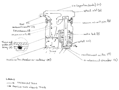
1. Top view of apparatus with vacuum shown in dotted lines.
2. Side view of apparatus with vacuum shown in dotted lines.
3. Cross sectional view showing inter nal exit pipe and airing attachment.
Detailed Description of Invention
As previously mentioned, the present invention is an apparatus for the
collecting
and separating of amalgam solids from a mixture of solids, liquids and air
present in a dental vacuum stream.
The present invention is represented in Fig. 1, Fig. 2 and Fig. 3.
Fig. 1 - Top View
A top view of the invention in Fig 1 shows the connection of the dental vacuum
tube at patient (4) to the apparatus inlet (1). The cronnection of the outlet
in
shadow (5) to the typical dental vacuum pump (3). The mixture street typically
enters through an inlet at the top of the apparatus and exists via an outlet
of the
bottom or base of the apparatus.
Fig. 2 - Side View
A side view of the invention is represented in Fig 2. T'he lid (9) also
functions as
the inlet (1 ) and liquid, particle and air separation chambers. A mechanical
connection (2) and o-ring seal (8) is used to connecir the lid (9),
sedimentation
chamber (3) and filtration chamber (~) to the body (gig). The seal is liquid
and
vacuum tight. The sedimentation chamber (3) and the filtration chamber (6) may
be disconnected from the body (7) by releasing the mechanical connection (2).
Thus enabling cleaning, recycling, replacement or disposal without specialized
staff or equipment. The outlet (2) can be clearly seen and referenced in Fig
1.
Fig. 3 - Cross Section
In the preferred embodiment, the dental mixture enters the invention through
the
inlet(1 ) or the optional inlet (10). Both inlet are located in the lid which
also
functions as a separation chamber (11 ). In this chamlaer, the liquid and
particles
are directed towards the sedimentation zone (5) via an extension of the lid
(3).
The air is permitted to flow out of the apparatus unobstructed by passing
through
an orifice in the lid extension (4) thus preventing vacmum pressure reduction
and
continuing through a vacuum air exit pipe (9) and out tll~e outlet (12).
The liquid and particle is collected in sedimentation zone (5). The heavy
3


CA 02442513 2003-09-23
particles collect at the base of the sedimentation zone due to gravity. The
liquid
with dissolved heavy metals rises and over flows ini~o the media bed (~). The
liquid passes through the media bed assisted by gravity and collects in the re-

entrainment chamber (6). The purified water is then re-entrained with the
vacuum air via on an orifice (7) located in the vacuum air exit pipe (8). The
purified water (air mixture exit's the apparatus via outlet (12) and continues
to the
vacuum pump.
The apparatus including lid, body, sedimentation chanmber and filtratian
chamber
is rotationally moulded thus reducing production cost.
From the foregoing, it will be appreciated that although the embodiment of the
invention have been described various modification may be made without
deviating from the spirit of the invention. According the invention is only
limited
by the claims-

Representative Drawing
A single figure which represents the drawing illustrating the invention.
Administrative Status

For a clearer understanding of the status of the application/patent presented on this page, the site Disclaimer , as well as the definitions for Patent , Administrative Status , Maintenance Fee  and Payment History  should be consulted.

Administrative Status

Title Date
Forecasted Issue Date Unavailable
(22) Filed 2003-09-23
(41) Open to Public Inspection 2005-03-23
Dead Application 2006-09-25

Abandonment History

Abandonment Date Reason Reinstatement Date
2005-09-23 FAILURE TO PAY APPLICATION MAINTENANCE FEE

Payment History

Fee Type Anniversary Year Due Date Amount Paid Paid Date
Application Fee $150.00 2003-09-23
Owners on Record

Note: Records showing the ownership history in alphabetical order.

Current Owners on Record
BARRETT, RICHARD
Past Owners on Record
None
Past Owners that do not appear in the "Owners on Record" listing will appear in other documentation within the application.
Documents

To view selected files, please enter reCAPTCHA code :


To view images, click a link in the Document Description column. To download the documents, select one or more checkboxes in the first column and then click the "Download Selected in PDF format (Zip Archive)" or the "Download Selected as Single PDF" button.

List of published and non-published patent-specific documents on the CPD .

If you have any difficulty accessing content, you can call the Client Service Centre at 1-866-997-1936 or send them an e-mail at CIPO Client Service Centre.


Document
Description 
Date
(yyyy-mm-dd) 
Number of pages   Size of Image (KB) 
Abstract 2003-09-23 1 45
Description 2003-09-23 4 240
Claims 2003-09-23 3 147
Drawings 2003-09-23 2 111
Representative Drawing 2003-11-07 1 26
Cover Page 2005-03-03 2 67
Assignment 2003-09-23 2 57
Correspondence 2003-10-21 1 13