Note: Descriptions are shown in the official language in which they were submitted.
CA 02442558 2003-02-04
WO 03/012362 PCT/CA02/01191
TITLE: CAMOUFLAGE MATERIAL FOR THE
TEMPERATE ENVIRONMENT
FIELD OF THE INVENTION
The present invention relates to materials having a
camouflage pattern applied thereon, and more specifically it relates
to a camouflage material having visual and near infrared
camouflage capabilities in a temperate environment.
BACKGROUND OF THE INVENTION
Traditionally, the Canadian military uniform is olive green in
colour. This type of uniform provides adequate camouflage in a
majority of circumstances. However, with the advance of
technology of detection such as night vision, there is a need for a
camouflage material that can provide camouflage in both the visual
(400-780 nm) and near infrared (780-2000 nm) regions of the
spectral range to increase the survivability of soldiers in the field.
Although several camouflage materials having visual and near
infrared camouflage properties may exist in the prior art, there is no
known camouflage material that has advantageous camouflage
properties to deceive modern vision equipment in a temperate
Canadian environment.
As such, it may be appreciated that there continues to be a
need for a camouflage pattern and material having advantageous
1
CA 02442558 2003-02-04
WO 03/012362 PCT/CA02/01191
camouflage properties in the visual and near infrared spectral
ranges of a temperate environment.
SUMMARY OF THE INVENTION
In the present invention, however, there is provided a
camouflage material having an improved camouflage pattern
applied thereto. This camouflage pattern has camouflage
properties in the visual and near infrared spectral ranges of a
temperate environment. The camouflage pattern can be applied to
a variety of fabric materials such as cotton, textile, acetate, acrylic,
latex, silk, fibreglass, polyester, Kevlar, wool, nylon, rayon and
neoprene. The camouflage pattern can also be applied to solid
objects and other rigid surfaces without modification.
In a first feature of the present invention, there is provided a
camouflage material having a granitic aspect made of intermixed
colored grains each exhibiting one of the colors:
light green having a dominant wavelength of about 566.70
nm; a luminance factor of about 13.10% and a saturation
factor of about 44.70%;
brown having a dominant wavelength of about 583.0 nm; a
luminance factor of about 9.30%, and a saturation factor of
about 31.60%;
average green having a dominant wavelength of about
569.36 nm; a luminance factor of about 5.24%, and a
saturation factor of about 38.50%; and
2
CA 02442558 2003-02-04
WO 03/012362 PCT/CA02/01191
black having a dominant wavelength of about 582.34 nm; a
luminance factor of about 2.68%, and a saturation factor of
about 4.01 %.
The camouflage material of the present invention has
camouflage properties in the visual and near infrared spectral range
of a temperate environment and provides optimum results when
used on targets less than preferably one square meter in size at a
distance ranging from 30 to 350 meters.
In another feature of the present invention, each grain in the
granitic aspect is a rectangular element having side dimensions of
about 4 mm by 2 mm. This visual aspect is further composed of:
about 21 % colored elements exhibiting the color light green;
about 6 % colored elements exhibiting the color brown;
about 48 % colored elements exhibiting the color average green,
and
about 25% colored elements exhibiting the color black.
The predominance of the colors average green and black in
the camouflage material is believed to contribute to a large degree
to the effectiveness of this material.
The word element is used herein to designate a single dot, a
blot or a spot of color having a rectangular shape. Due to the fact
that the camouflage pattern was initially generated using a
computer, each element is the material equivalent of a pixel on a
computer screen.
3
CA 02442558 2003-02-04
WO 03/012362 PCT/CA02/01191
In yet another feature of the present invention, the granitic
aspect mentioned above comprises colored clusters of colored
elements and each cluster is defined by saw-toothed edges. This
visual aspect and the mentioned colors has the advantageous
properties of simulating the appearance and the colors including
luminance and saturation factors of an average background of a
temperate environment giving, for example the appearance of a
dense foliage canopy. Again, this visual aspect is believed to
contribute to a large extent to the effectiveness of the camouflage
material.
Still another feature of the camouflage pattern described
herein is that it can be applied to common fabric materials and
other substrates using conventional fabric dying, printing or
painting techniques.
Other advantages and novel features of the present invention
will become apparent from the following detailed description.
BRIEF DESCRIPTION OF THE DRAWINGS
Because the camouflage material of present invention is not
limited to a specific substrate but has uniqueness in the camouflage
pattern applied thereto, the following detailed description focuses
on the details of this pattern. It should be understood that this
camouflage pattern is applied to various objects to make inventive
manufactures.
4
CA 02442558 2003-02-04
WO 03/012362 PCT/CA02/01191
One embodiment of the camouflage pattern is illustrated in
the accompanying drawings, in which:
FIG. 1 is a graph showing the spectral curve in the visual and near
infrared regions of the spectral range for the color light green
used in the camouflage pattern;
FIG. 2 is a graph showing the spectral curve in the visual and near
infrared regions of the spectral range for the color brown
used in the camouflage pattern;
FIG. 3 is a graph showing the spectral curve in the visual and near
infrared regions of the spectral range of the color average
green used in the camouflage pattern;
FIG. 4 is a graph showing the spectral curve in the visual and near
infrared regions of the spectral range for the color black used
in the camouflage pattern;
FIG. 5 illustrates a plan view of the final camouflage pattern
resulting from a superimposition of the light green, brown,
average green and black sub-patterns;
FIG. 6 illustrates a plan view of the light green sub-pattern;
FIG. 7 illustrates a plan view of the brown sub-pattern;
5
CA 02442558 2003-12-15
FIG. 8 illustrates a plan view of the average green sub-pattern, and
FIG. 9 illustrates a plan view of the black sub-pattern.
DETAILED DESCRIPTION OF THE PREFERRED
ENMBODIMENT OF THE PATTERN APPLIED TO THE
CAMOUFLAGE MATERIAL OF THE PRESENT
INVENTION
While this invention is susceptible of embodiments in many
different forms, there is shown in the drawings and will be
described in details herein a specific embodiment of the
camouflage pattern, with the understanding that the present
disclosure is to be considered as an example of the principles of the
invention and is not intended to limit the invention to the
embodiment illustrated and described.
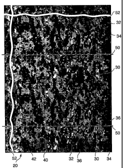
The camouflage pattern 20 includes four sub-patterns 22, 24,
26, 28 overlaid on one another to provide an overall or final
camouflage pattern 20. Each sub-pattern has a specific color with
specific color distribution, thus providing a distinct individual
pattern. When the sub-patterns are superimposed over one another,
they are intermingled and hence provide a resulting camouflage
pattern that consists of a combination of all four sub-patterns 22,
24, 26, 28 each being distinguishable from the other by its color.
In this case, the colors of the sub-patterns are generally light green
30, brown 32, average green 34 and black 36. Each of the sub-
patterns 22, 24, 26, 28 is illustrated in FIGS. 6-9 respectively. The
spectral curve in the visual and near infrared regions for each of the
6
CA 02442558 2003-12-15
colors 30, 32, 34 and 36 is illustrated in FIGS. 1-4 respectively.
The final camouflage pattern 20 is illustrated in FIG. 5.
Each sub-pattern is made of its respective colored elements
40. The elements 40 have a rectangular shape having side
dimensions of approximately 2 mm by 4 mm. The elements 40 are
distributed in colored clusters as exemplified at 42 in FIGS. 5-9,
having irregular multi-form shapes. Each cluster 42 has saw-
toothed edges with no straight line and no smooth curve. When all
four sub-patterns 22, 24, 26, 28 are superimposed over one another,
the entire surface of the final camouflage pattern is aggregately
covered by the colored elements 40 and by the clusters 42 of
elements.
The resulting camouflage pattern 20, as illustrated in FIG. 5,
has a granitic aspect. The rectangular elements 40 and clusters 42
of elements in this visual aspect can be, for example, compared to
the facetted crystal-like grains of a polished granit stone. This
analogy is used herein for convenience to describe the structureof
the camouflage pattern according to the preferred embodiment. It
is believed that this granitic aspect of the camouflage pattern, using
conventional camouflage colors, has merits on its own as a
camouflage pattern in at least the visual spectral range.
As it will be understood, all four sub-patterns 22, 24, 26, 28
and the final pattern 20 have been generated using a computer,
wherein each element 40 of this final pattern and sub-patterns is the
material equivalent of a pixel on a computer screen. The computer
7
CA 02442558 2003-12-15
illustrations of the final pattern and sub-patterns have been scaled
up so that each pixel on the computer screen forms the colored
element 40 having the mentioned dimensions. The use of a
computer has made it possible to generate a pattern from images of
green backgrounds and thereby ensures a good merging of the
pattern with the backgrounds.
In the illustrations of FIGS. 5-9, each of the colors light
green 30, brown 32, average green 34 and black 36 is represented
in different shades of black. As mentioned before, the black
representation of the camouflage pattern in FIG. 5 can be
compared to that of black granit. However, it will be appreciated
that when the grains in each sub-pattern exhibit its intended colors,
the final camouflage pattern 20 mimics the background of a
temperate environment. This later visual aspect of the camouflage
pattern is intended for providing the desired camouflage properties
in the visual and near infrared spectral ranges.
In the preferred camouflage pattern 20, the . approximate
color specifications for each sub-pattern are given in Tables 1-4 as
follows.
8
CA 02442558 2003-02-04
WO 03/012362 PCT/CA02/01191
Table 1: Specifications for the Color Light Green (30)
Standards applied with
Illuminant C, 2 deg CIE 1931/ CIE LAB 1976
x coordinate (CIE 1931) 0.3614
y coordinate (CIE 1931) 0.4339
Dominant Wavelength 566.70 nm
Luminance factor Y% 13.10
Saturation factor S% 44.70
Component L* 42.90
Component a* -13.40
Component b* 26.80
Table 2: Specifications for the Color Brown (32)
Standards applied with
Illuminant C, 2 deg CIE 1931/ CIE LAB 1936
x coordinate (CIE 1931) 0.3802
y coordinate (CIE 1931) 0.3649
Dominant Wavelength 583.00 nm
Luminance factor Y% 9.30
Saturation factor S% 31.60
Component L* 36.50
Component a* 4.60
Component b* 14.50
9
CA 02442558 2003-02-04
WO 03/012362 PCT/CA02/01191
Table 3: Specifications for the Color Average Green (34)
Standards applied with
Illuminant C, 2 deg CIE 1931/ CIE LAB 1976
x coordinate (CIE 1931) 0.3600
y coordinate (CIE 1931) 0.4098
Dominant Wavelength 569.36 nm
Luminance factor Y% 5.24
Saturation factor S% 38.50
Component L* 27.41
Component a* -6.78
Component b* 16.46
Table 4: Specifications for the Color Black (36)
Standards applied with
Illuminant C, 2 deg CIE 1931/CIE LAB 1971
X coordinate (CIE 1931) 0.3188
Y coordinate (CIE 1931) 0.3224
Dominant Wavelength 582.34 nm
Luminance factor Y% 2.68
Saturation factor S% 4.01
Component L* 18.71
Component a* 0.41
Component b* 1.21
CA 02442558 2003-12-15
In the camouflage pattern according to the preferred
embodiment, each color represents a certain portion of the whole
camouflage surface. The preferred proportions for the four colors
are as follows:
Table 5: Color Content in the Final Camouflage Pattern
Color Portion of the Final Pattern
Light Green (30) About 21 %
Brown (32) About 6%
Average Green (34) About 48%
Black (36) About 25%
Referring to FIG. 5, the camouflage pattern 20 consists of
repeating units. In this case, the section between the dash lines 50
in FIG. 5 represents one repeating unit, whereas the lines 52
having sinusoidal appearance indicate that the pattern can have
indeterminate length. Preferably the camouflage pattern is applied
to substrate sections, each measuring about 2 meters by 2 meters.
The camouflage pattern is reproduced on a fabric material
using a conventional dying, printing or painting process. Each sub-
pattern is applied independently in sequence starting with the light
green layer, the brown layer, the average green layer and the black
layer. When there is an overlapping of elements 40 from one sub-
pattern over the other, most of the overlapped elements 40 have the
average green 34 or black color 36.
I1
CA 02442558 2003-12-15
The above color specifications and the amount of colored
elements 40 in each sub-pattern 22, 24, 26, 28 were optimised for
the temperate environment. This was achieved by collecting data
of the temperate environment of Canadian landscapes over a period
of time, using a camera and a field spectrophotometer.
Photographic recordings and spectral measurements have been
used to define the structure of these environments and the spectral
properties of the colors in these environments. These data were
digitised and processed into a computer to obtain each sub-pattern.
However, because the present invention consists of a
camouflage material, it is not deemed necessary to provide further
details to explain the algorithms and other software used to obtain
the original sub-patterns and the final camouflage pattern shown in
FIGS. 5-9.
It will be appreciated that several methods can be used to
reproduce the sub-patterns and final pattern on the camouflage
material according to the present invention. It is believed that one
can employ different techniques such as scanning, stencils, ~
templates or photocopying. to apply the camouflage pattern on
various types of fabric materials and various substrates using dies
or inks. These techniques are known to those skilled in the art and
therefore, additional details concerning the dying, printing or
painting of the camouflage pattern on a substrate is deemed
unnecessary.
12
CA 02442558 2003-12-15
The camouflage material according to the preferred
embodiment has advantageous camouflage properties in the visual
and near infrared spectral range and provides optimum results
when used in the temperate environment, at a distance ranging
from 30 to 350 meters, and on targets less than one square meter,
such as a soldier.
It should be noted, however, that the element dimension size
of 2 mm by 4 mm and the patterns which are composed of these
elements together with the colors, luminance and saturation factors
represent an optimum combination. Any deviation from these
values may diminish the camouflage effect.
Although the color specifications and element sizes
comprised in the camouflage pattern, as specified herein, are
somewhat narrow in scope, it will be evident to those skilled in.the
art that changes and modifications may be made therein without
departing from the essence of this invention, as set forth in the
appended claims.
13