Language selection

Search

Patent 2442672 Summary

Third-party information liability

Some of the information on this Web page has been provided by external sources. The Government of Canada is not responsible for the accuracy, reliability or currency of the information supplied by external sources. Users wishing to rely upon this information should consult directly with the source of the information. Content provided by external sources is not subject to official languages, privacy and accessibility requirements.

Claims and Abstract availability

Any discrepancies in the text and image of the Claims and Abstract are due to differing posting times. Text of the Claims and Abstract are posted:

  • At the time the application is open to public inspection;
  • At the time of issue of the patent (grant).
(12) Patent: (11) CA 2442672
(54) English Title: LINEAR FLUORESCENT LAMP END CAP LOCKING SYSTEM
(54) French Title: SYSTEME DE VERROUILLAGE DE CULOT DE LAMPE FLUORESCENTE LINEAIRE
Status: Deemed expired
Bibliographic Data
(51) International Patent Classification (IPC):
  • B65D 85/42 (2006.01)
  • B65D 71/46 (2006.01)
(72) Inventors :
  • HARDY, GREGORY J. (United States of America)
(73) Owners :
  • OSRAM SYLVANIA INC. (United States of America)
(71) Applicants :
  • OSRAM SYLVANIA INC. (United States of America)
(74) Agent: FETHERSTONHAUGH & CO.
(74) Associate agent:
(45) Issued: 2007-07-31
(22) Filed Date: 2003-09-25
(41) Open to Public Inspection: 2004-05-27
Examination requested: 2003-10-10
Availability of licence: N/A
(25) Language of filing: English

Patent Cooperation Treaty (PCT): No

(30) Application Priority Data:
Application No. Country/Territory Date
60/429,999 United States of America 2002-11-27
10/394,857 United States of America 2003-03-21

Abstracts

English Abstract

A locking system for two linear fluorescent lamps comprises an endcap formed to receive two linear fluorescent lamps (Fig. 3). The endcap has two chambers formed by the outside surfaces of endcap and a central partition. Each of the chambers has a forward portion and a rearward portion. The endcap has a height H equal to the diameter of the fluorescent lamps, a width W equal to twice the diameter of the fluorescent lamps and a length, for example, 4 to 6 inches, that is substantially less than the length of the lamps, which can be one to eight feet long. A stop is formed in each of the chambers at the forward portion to retain the lamps within the endcap. Each of the stops, in the form of a reverse corner, extends inwardly toward the center of the endcap and has a first panel with a first dimension equal to the height H and a second panel with a second dimension that is greater than one half of said height H but less than the height H.


French Abstract

Un système de verrouillage de deux lampes fluorescentes linéaires comprend un embout formé pour recevoir les deux lampes fluorescentes linéaires (Fig. 3). L'embout est doté de deux chambres formées par les surfaces extérieures de l'embout et une portion centrale. Chacune des chambres comporte une partie avant et une partie arrière. L'embout a une hauteur H égale au diamètre des lampes fluorescentes, une largeur W égale à deux fois le diamètre des lampes fluorescentes et une longueur, par exemple, de 4 à 6 pouces, qui est substantiellement inférieure à la longueur des lampes, qui peut être de un à huit pieds. Une butée est formée dans chacune des chambres à la portion avant pour retenir les lampes dans l'embout. Chacune des butées, ayant la forme d'un coin inversé, s'étend à l'intérieur vers le centre de l'embout et un premier panneau ayant une première dimension également à la hauteur H et un deuxième panneau ayant une deuxième dimension qui est plus grande que la moitié de ladite hauteur H mais moins que la hauteur H.

Claims

Note: Claims are shown in the official language in which they were submitted.


7
CLAIMS:

What is claimed is:

1. A locking system for two linear fluorescent lamps, comprising:
an endcap formed to receive two linear fluorescent lamps, said endcap having
two
chambers each with a forward portion and a rearward portion, said endcap
having a height
equal to the diameter of said fluorescent lamps, a width equal to twice the
diameter of said
fluorescent lamps and a length that is substantially less than the length of
said lamps; and
a stop formed in each of said chambers at said forward portion, each of said
stops
extending inwardly toward the center of said endcap and having a first panel
with a first
dimension equal to said height and a second panel with a second dimension that
is greater than
one half of said height.

2. The locking system of Claim 1 wherein said endcap has an upper surface and
a lower
surface, and one of said surfaces has a tab formed therein, said tab extending
inwardly.

3. A linear fluorescent lamp package comprising two linear fluorescent lamps
arranged
side-by-side and provided with an endcap at each end, each of said endcaps
having two
chambers each with a forward portion and a rearward portion, said endcaps
having a height
equal to the diameter of said fluorescent lamps, a width equal to twice the
diameter of said
fluorescent lamps and a length that is substantially less than the length of
said lamps; each of
said chambers being formed to receive a lamp and having a stop formed therein,
each of said
stops extending inwardly toward the center of said endcap and having a first
panel with a first
dimension equal to said height and a second panel with a second dimension that
is greater than
one half of said height.

4. The linear fluorescent lamp package of Claim 3 wherein each of said endcaps
has an
upper surface and a lower surface and one of said surfaces has a tab formed
therein, said tab
extending inwardly, and an adhesive fixing said tab to one of said lamps.


8

5. The package of Claim 4 wherein said adhesive is initially flowable.

Description

Note: Descriptions are shown in the official language in which they were submitted.


CA 02442672 2006-07-04

Page 2

LINEAR FLUORESCENT LAMP END CAP LOCKING SYSTEM
TECHNICAL FIELD
This invention relates to linear fluorescent lamps and more particularly to
packaging for such
lamps. Still more particularly it relates to packaging for small quantities of
such lamps.
BACKGROUND ART
Previous techniques for packaging small quantities of fluorescent lamps (for
example, two
lamps or four lamps) employed endcaps forrned from folding carton material or
paper or
cardboard with inwardly extending dimples in an F-shape to extend across the
ends of the
lamps and a shrink-wrap to complete the package.
While workable, these endcaps were difficult to manufacture and difficult to
automate.
Additionally, the shrink-wrap was difficult to apply and added to the cost of
lamps.
SUMMARY OF INVENTION
It is, therefore, desirable to obviate the disadvantages of the prior art.
It is also desirable to enhance fluorescent lamp packaging.

It is further desirable to provide endcaps that do not have to be shrink-
wrapped.

In accordance with an aspect of the present invention there is provided a
locking system for
two linear fluorescent lamps, comprising: an endcap formed to receive two
linear fluorescent
lamps, the endcap having two chambers each with a forward portion and a
rearward portion,
the endcap having a height equal to the diameter of the fluorescent lamps, a
width equal to
twice the diameter of the fluorescent lamps and a length that is substantially
less than the


CA 02442672 2006-07-04

Page 2a

length of the lamps; and a stop formed in each of the chambers at the forward
portion, each of
the stops extending inwardly toward the center of the endcap and having a
first panel with a
first dimension equal to the height and a second panel with a second dimension
that is great
than one half of the height.
In accordance with another aspect of the present invention there is provided a
linear
fluorescent lamp package comprising two linear fluorescent lamps arranged side-
by-side and
provided with an endcap at each end, each of the endcaps having two chambers
each with a
forward portion and a rearward portion, the endcaps having a height equal to
the diameter of
the fluorescent lamps, a width equal to twice the diameter of the fluorescent
lamps and a
length that is substantially less than the length of the lamps; each of the
chambers being
formed to receive a lamp and having a stop formed therein, each of the stops
extending
inwardly toward the center of the endcap and having a first panel with a first
dimension equal
to the height and a second panel with a second dimension that is greater than
one half of the
height.

In an exemplary embodiment, a locking system for two linear fluorescent lamps
comprises an
endcap formed to receive two linear fluorescent lamps, the endcap having two
chambers each
with a forward portion and a rearward portion. The endcap has a height equal
to the diameter
of the fluorescent lamps, a width equal to twice the diameter of the
fluorescent lamps, a
divider between the two


CA 02442672 2003-09-25
Attorney Docket No.: 02-1-873
Page 3

chambers that at least in one area has a thickness that is three times the
thickness of the
endcap material, and a length that is substantially less than the length of
said lamps. A stop
is formed in each of the chambers at the forward portion and each of the stops
extends
inwardly toward the center of the endcap and has a first leg with a first
dimension equal to
the height of endcap and a second leg with a second dimension that is greater
than one half of
the height. The inwardly-formed stop locks behind the lamp base pins when
lamps are
inserted into the chambers.

Additionally, each endcap has an upper surface and a lower surface, and one of
the surfaces
has a tab formed therein, the tab extending inwardly of the endcap and
positioning between
the lamps, adding to the separation between the lamps An adhesive is dispensed
through the
opening formed by the tab and adheres one of the lamps to the tab thus
securing the endcaps
to the lamps and eliminating the need for a shrink-wrap

BRIEF DESCRIPTION OF THE DRAWINGS

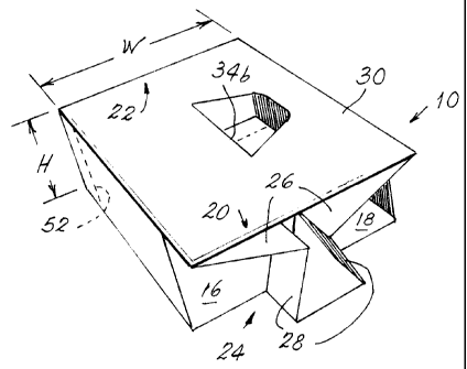
Fig. 1 is a perspective view of an endcap illustrating an embodiment of the
invention;

Fig, 2 is an elevational end view of an endcap with the thickness of the
material exaggerated
for clarity;

Fig. 3 is a similar, diagrammatic view of an endcap with a pair of lamps
enclosed by the
endcap and the thickness of the material minimized, again, for clarity; and

Fig. 4 is a perspective view of an endcap in accordance with an aspect of the
invention before
the corners are folded in.


CA 02442672 2003-09-25
Attorney Docket No.: 02-1-873
Page 4

BEST MODE FOR CARRYING OUT THE INVENTION

For a better understanding of the present invention, together with other and
further objects,
advantages and capabilities thereof, reference is made to the following
disclosure and
appended claims in conjunction with the above-described drawings.

Referring now to the invention with greater particularity, there is shown in
Fig. 1 a locking
system for two linear fluorescent lamps, comprising an endcap 10 formed to
receive two
linear fluorescent lamps 12, 14 (Fig. 3). The endcap 10 has two chambers 16,
18 formed by
the outside surfaces of endcap 10 and a central partition 19. Each of the
chambers has a
forward portion 20 and a rearward portion 22. The endcap 10 has a height H
equal to the
diameter of the fluorescent lamps, a width W equal to twice the diameter of
the fluorescent
lamps, a center divider 19 that at least in one area has a thickness that is
three times the
thickness of the endcap material, as will be explained hereinafter, and a
length, for example,
4 to 6 inches, that is substantially less than the length of the lamps, which
can be from one to
eight feet long or greater. A stop 24 is formed in each of the chambers at the
forward portion
to retain the lamps within the endcap. Each of the stops 24, in the form of a
reverse
corner, extends inwardly toward the center of the endcap and has a first panel
26 with a first
dimension equal to the height H and a second panel 28 with a second dimension
that is
20 greater than one half of said height H but less than the height H. When the
panels are
reverse-folded they must extend beyond the lamp base pins, insuring that the
panels cannot
collapse to original position 50 (shown in Fig. 4)

The stops 24 are formed by cutting the sides 50 of the endcap from top to
bottom to form a
slit 52 and by cutting the lower surface 32 to form a slit 54, thus allowing
the corner to be
pushed inwardly toward the center of endcap 10 and forming the stop 24. The
appropriate
slits are shown by dashed lines in Fig. 4.

The endcaps 10 have an upper surface 30 and a lower surface 62 that have tabs
34a and 34b
formed therein that extend inwardly and rest against center divider 19, thus
effectively
making at least a portion of the divider 19 three times the thickness of the
endcap material.

- - ----- --------


CA 02442672 2003-09-25
Attorney Docket No.: 02-1-873
Page 5

This feature is shown most clearly in Fig. 2 and provides for greater
separation between the
lamps 12 and 14.

Again referring to Fig. 2, the endcap is preferably made from a single sheet
of material that is
scored to allow folding of the material into the endcap unit. Thus, the endcap
structure
comprises an extension 60, the center partition 19, a top 62 for chamber 18, a
descending
wall 64, a bottom 66, an ascending wall 68 for chamber 16 and an overlying
cover 70. Glue
is applied between extension 60 and bottom 66 and overlying cover 70 and top
62.

As can be seen from Figs. 1 and 4, the slits 52 and 54 can be formed on both
ends of the
endcap, although only one set will be employed to form the stops 24.

The endcaps when assembled are used to form a fluorescent lamp package 36 that
comprises
two linear fluorescent lamps 12, 14 arranged side-by-side with an endcap 10 at
either end
(see Fig. 3). The endcaps are slid upon the lamps until contact is made with
the stops 24.

A quantity of adhesive 40 about the size of a U.S. quarter (i.e., about one
inch or 2.54 cm in
diameter) is dispensed through the opening 35 provided by tabs 34a and 34b and
adheres to
the exposed lamp and tab 34b on both endcaps. The adhesive should not be
exposed to the
outer surface 70 of the endcap. Note: the second lamp is locked in place by
the two endcaps
adhering to the same lamp. The left and right endcaps must have the same
opening
orientation to ensure that the same lamp is adhered to both endcaps.

It is preferable that the adhesive 40 will release from the glass lamp cleanly
when the
endcaps are removed by the ultimate user of the lamps; also the adhesive must
have a bond
sheer strength that can withstand user handling and remain in place until the
user desires to
use the lamps. In a preferred embodiment of the invention, this adhesive is
preferably one
designated HM2703 and available from the H. B. Fuller Company, or one
designated H5077
and available from Bostik Findley.
A preferred material for the endcaps is 0.020 CCRB clay coated recycled board.


CA 02442672 2003-09-25
Attorney Docket No.: 02-1-873
Page 6

Thus, there is provided by this invention an endcap for packaging linear
fluorescent lamps
that obviates the use of shrink-wrap and that is easy to manufacture and to
assemble. The
design readily adapts to the use of automated equipment and contributes to
material and
equipment maintenance savings.

While there have been shown and described what are at present considered to be
the
preferred embodiments of the invention, it will be apparent to those skilled
in the art that
various changes and modification can be made herein without departing from the
scope of
the invention as defined by the appended claims.

Representative Drawing
A single figure which represents the drawing illustrating the invention.
Administrative Status

For a clearer understanding of the status of the application/patent presented on this page, the site Disclaimer , as well as the definitions for Patent , Administrative Status , Maintenance Fee  and Payment History  should be consulted.

Administrative Status

Title Date
Forecasted Issue Date 2007-07-31
(22) Filed 2003-09-25
Examination Requested 2003-10-10
(41) Open to Public Inspection 2004-05-27
(45) Issued 2007-07-31
Deemed Expired 2014-09-25

Abandonment History

There is no abandonment history.

Payment History

Fee Type Anniversary Year Due Date Amount Paid Paid Date
Registration of a document - section 124 $100.00 2003-09-25
Application Fee $300.00 2003-09-25
Request for Examination $400.00 2003-10-10
Maintenance Fee - Application - New Act 2 2005-09-26 $100.00 2005-09-01
Maintenance Fee - Application - New Act 3 2006-09-25 $100.00 2006-08-18
Final Fee $300.00 2007-05-10
Maintenance Fee - Patent - New Act 4 2007-09-25 $100.00 2007-08-17
Maintenance Fee - Patent - New Act 5 2008-09-25 $200.00 2008-08-19
Maintenance Fee - Patent - New Act 6 2009-09-25 $200.00 2009-08-12
Maintenance Fee - Patent - New Act 7 2010-09-27 $200.00 2010-08-20
Registration of a document - section 124 $100.00 2011-04-15
Maintenance Fee - Patent - New Act 8 2011-09-26 $200.00 2011-08-09
Maintenance Fee - Patent - New Act 9 2012-09-25 $200.00 2012-08-13
Owners on Record

Note: Records showing the ownership history in alphabetical order.

Current Owners on Record
OSRAM SYLVANIA INC.
Past Owners on Record
HARDY, GREGORY J.
OSRAM SYLVANIA INC.
Past Owners that do not appear in the "Owners on Record" listing will appear in other documentation within the application.
Documents

To view selected files, please enter reCAPTCHA code :


To view images, click a link in the Document Description column. To download the documents, select one or more checkboxes in the first column and then click the "Download Selected in PDF format (Zip Archive)" or the "Download Selected as Single PDF" button.

List of published and non-published patent-specific documents on the CPD .

If you have any difficulty accessing content, you can call the Client Service Centre at 1-866-997-1936 or send them an e-mail at CIPO Client Service Centre.


Document
Description 
Date
(yyyy-mm-dd) 
Number of pages   Size of Image (KB) 
Abstract 2003-09-25 1 26
Description 2003-09-25 5 203
Drawings 2003-09-25 2 46
Claims 2003-09-25 2 53
Representative Drawing 2003-11-17 1 9
Cover Page 2004-04-30 1 43
Claims 2006-07-04 2 52
Description 2006-07-04 6 235
Abstract 2006-07-04 1 23
Representative Drawing 2007-07-11 1 11
Cover Page 2007-07-11 1 44
Prosecution-Amendment 2003-10-10 1 35
Assignment 2003-09-25 6 268
Prosecution-Amendment 2006-01-04 2 41
Prosecution-Amendment 2006-07-04 7 215
Correspondence 2007-05-10 1 39
Assignment 2011-04-15 10 540