Note: Descriptions are shown in the official language in which they were submitted.
CA 02442749 2003-09-29
P036 728/W0/1
Rotor gap control module
The invention relates to a rotor blade control module
for installation in a turbomachine through which a
fluid flows in a main direction of flow and which has a
rotatable rotor, with rotor blades which are at a
predetermined distance from one another in the
direction of rotation of the rotor, and a housing,
which at least in sections surrounds the rotor so as to
form a rotor gap, the rotor gap control module
comprising at least one sealing element, which delimits
the rotor gap in sections and can be moved into the
rotor gap, and an actuator unit, which moves when the
sealing element is operating.
In turbomachines, a term which encompasses, for
example, turbines, pumps, compressors or fans, the
rotor gap between the stationary rotary housing and
rotating rotor represents a source of flow losses and
therefore a cause of reduced efficiency. The flow
losses are caused on the one hand by the formation of
vortices and flow detachment in or at the rotor gap,
which also leads to increased flow noise, and on the
other hand as a result of compensating flow which is
directed oppositely to the main direction of flow
through the rotor and limits the pressure difference
which can be achieved between the high-pressure side
and the low-pressure side of the turbomachine.
In the case of an ideal, loss-free turbomachine, a
rotor gap would not be present. In practice, however,
this is impossible, since in this case the tips of the
rotor blades would come into contact with the housing
and grind against the housing when the rotor rotates,
leading to wear. This problem is particularly
pronounced in turbomachines in which the rotors rotate
at a high rotation speed and/or are acted on by high
temperatures, such as for example in aircraft engines
and gas turbines and in exhaust-gas turbochargers. In
CA 02442749 2003-09-29
P036 728/W0/1
- 2 -
turbomachines of this type, the rotor blade lengthens
as a function of the temperature and the rotational
speed. In addition, the housing widens as a function of
the operating temperature. The rotor gap compensates
for the expansion of the housing and the lengthening of
the rotor blades without any possibility of the
turlaomachine being damaged.
The width of the rotor gap and therefore the losses
from the turbomachine consequently change as a function
of the rotational speed and the temperature in the
operating state which is prevailing at the time.
In practice, the rotor gap is generally set in such a
way that at a long-term operating point, at which the
turbomachine is generally operated, the rotor gap is as
small as possible. In the case of aircraft engines or
exhaust-gas turbochargers, this long-term operating
point lies, for example, at the travelling speed. At
the same time, when dimensioning the rotor gap in
practice account is taken of limit-load ranges and
start-up ranges of the turbomachine: the dimensions of
the rotor gap should be such that even under extreme
conditions damage to rotor blade and housing is avoided
with acceptable flow losses.
In practice, therefore, a certain wear to the housing
and rotor blade as a result of the starting-up of the
turbomachine or operation of the turbomachine in the
limit-load range is accepted with a view to optimizing
efficiency.
The prior art has proposed a number of solutions aimed
at achieving an optimum rotor gap, i.e. a rotor gap
width in which wear and flow losses are minimal, in all
operating ranges of the turbomachine.
For example, US 5,092,737 has described a device which
CA 02442749 2003-09-29
P036 728/W0/1
- 3 -
reduces the wear in the starting-up phase of a gas
turbine, during which housing and rotor heat up to
different extents, by changing the rotor gap width. The
device described in that document changes the rotor gap
passively by means of the thermal expansion of control
elements in the gas turbine housing wall located
opposite the rotor. In this case, the coefficients of
thermal expansion of the control elements are matched
to the operating states of the gas turbine in such a
way that the expansion of the housing corresponds to
the thermal expansion of the rotor blades at different
operating temperatures. The drawback of this passive
system is that the rotor gap can only be matched to the
thermal expansion but not to the lengthening of the
rotor blades under the action of centrifugal force,
which in practice is an equally important parameter.
Moreover, the response time of this system is very
slow.
The response time and also the possibilities of
influencing the width of the rotor gap are improved in
active systems in which the rotor gap is actively
changed by actuator units compared to the passive
systems.
US 5,906,473 has described an active system for a gas
turbine in which parts of the housing are selectively
cooled or heated with respect to the rotor, in order to
set the rotor gap by means of the thermal expansion of
the housing which is controlled in this way. The
drawback of this system, as before, Lies in the slow
response time, since to change the air gap the housing
first has to be brought to a predetermined temperature.
In the event of rapid changes in the operating state,
the system described in US 5,906,473 cannot adjust the
rotor gap sufficiently quickly. However, the active
heating of the housing wall does appear to make it
possible to adapt to a slow lengthening of the rotor
CA 02442749 2003-09-29
P036 728/W0/1
- 4 -
blades under the action of centrifugal force.
To improve the response time when setting the rotor gap
and to achieve more direct control of the rotor gap,
mechanically moved housing segments are fitted opposite
the rotor blades in the system described in
US 5,104,287 and US 5,096,375. The housing segments are
combined to form a continuous ring and are moved in the
radial direction toward the rotor blades by means of
threaded pins, so that the ring is contracted or
widened when the threaded pins rotate. The threaded
pins of all the housing segments are actuated together
via a synchronizer ring, thereby allowing the housing
segments to be adjusted together and at the same time,
so that the rotor gap can be set. A drawback of this
device is firstly the enormous outlay on design and
manufacturing technology which is required if virtually
play-free adjustment of the segments in the range of a
few tenths of a millimeter is desired, and secondly the
fact that the response time, as before, is still slow.
US 5,263,816 has described a device for rotor gap
control for a radial compressor, in which the rotor gap
is adjusted in the axial direction by means of a
displacement of the rotor with respect to the housing.
This principle too is of very complex design and has
only a moderately fast response time. Furthermore, the
system described in US 5,263,816 is restricted to
radial-flow turbomachines.
US 5,545,007 describes a ring of housing segments
opposite the rotor blades, which can be contracted and
widened by means of piezoelectric elements. The width
of the rotor gap between rotor blade tips and housing
segments and that between the segment ring is
determined by means of proximity sensors. Then, a
voltage is applied to the stationary piezo elements
arranged on a housing-side holder as a function of the
CA 02442749 2003-09-29
P036 728/W0/1
- 5 -
measured rotor gap, so that as a result of the
electrorestriction of the piezo elements, the segments
of the ring are moved toward or away from the rotor
blades. The drawback of the system described in
US 5,545,007 is the lack of stability of the segment
ring, since it is held exclusively by the piezoelectric
elements.
Further devices for adjusting the rotor gap are shown
in US 4,247,247 and in US 4,683,716, US 5,211,534 and
US 5,871,333.
US 4,247,247 shows an axial-flow turbine, in which the
housing, opposite the rotors, has a ring with a thin,
flexible wall. Annular pressure chambers, which can be
acted on by different pressures, are arranged behind
the thin wall. If the pressure in the pressure chambers
exceeds the pressure in the axial-flow turbine, the
wall bulges in controlled fashion and thereby reduces
the size of the rotor gap. The pressure chambers are
acted on by pressure in such a way that the size of the
rotor gap is reduced in the direction of flow.
In the case of the gas turbine described in
US 4,683,716, the housing wall, together with several
rows of stator blades, is pneumatically adjusted beyond
several compressor stages. For this purpose, a pressure
chamber, which extends over several rotor and stator
rows, is provided behind the housing wall. Supplying a
low pressure or a high pressure to the pressure chamber
prevents the rotor blades from rubbing against the
housing wall during start-up operations.
In US 5,211,534, the rotor gap is likewise adjusted
pneumatically. A sealing ring around the rotor, which
is composed of radially displaceable ring segments, is
contracted or widened by the action of compressed air
on the rigid ring segments.
CA 02442749 2003-09-29
P036 728/W0/1
- 6 -
The device described in US 5,781,333 also has housing
segments which are moved toward the rotor blades as a
result of compressed air being applied to pressure
chambers. To improve the response time, the pressure
chamber is provided with bleed valves for rapid
pressure equalization.
A drawback of the systems described in US 4,247,247,
US 4,683,716, US 5,211,534 and US 5,871,333 is that
rapid and selective adjustment of the rotor gap is not
possible.
US 6,142,477 describes an active sealing device which
is used to seal off bearings in gas turbines. The
active sealing device has sealing elements which are
automatically arranged close to a sealing disk without
coming into contact with the sealing disk when the
sealing disk rotates. For this purpose, the sealing
surface is designed as a magnetic ring which has
differently polarized regions which alternate in the
circumferential direction. When the magnetic ring is
rotating, these regions generate a magnetic flux, the
strength of which is dependent on the rotational speed
of the magnetic ring. The sealing elements are provided
with coils which react to the strength of the magnetic
field generated by the rotating ring and automatically
move onto or away from the magnetic ring depending on
the rotational speed of the magnetic ring and its
distance from the coils. The system described in
US 6,142,477 is therefore able to react automatically
_ to a change in the sealing gap. However, US 6,142,477
does not reveal how this system can be used to adjust a
rotor gap, since for this system to function it is
always necessary for there to be a continuous magnetic
ring on the mating sealing surface located opposite the
sealing elements.
To summarize, the above prior art does not disclose any
CA 02442749 2003-09-29
P036 728/W0/1
-
device in which the response time allows rapid
adjustment of the rotor gap.
The invention is therefore based on the object of
improving the rotor gap control module described in the
introduction in such a way that a more rapid response
is achieved.
According to the invention, this object is achieved by
the rotor gap control module of the type described in
the introduction by virtue of the fact that the
dimension of the sealing element in the direction of
rotation is smaller than the distance between two
successive rotor blades.
This solution is simple and is not known from the prior
art. All the documents cited above have sealing
elements in the form of segments of a circle, the
dimensions of which are larger in the direction of
rotation than the distance between two successive rotor
blades. As a result, in the conventional systems for
setting the rotor gap, the moving masses are so great
that they can only react slowly to changes in the rotor
gap. Moreover, on account of the fact that the
conventional housing segments extend over a plurality
of rotor blades, it is not possible to deliberately
adapt the rotor gap in the event of asymmetric or
elliptical deformation of the rotor or the housing.
These drawbacks are avoided by the structurally simple
solution according to the invention. The dimensions of
the sealing element according to the invention mean
that the moving masses of the sealing element are
smaller and can be moved significantly more quickly.
Tn this context, the solution according to the
invention provides for the dimensions of the sealing
element in the direction of rotation to be
CA 02442749 2003-09-29
P036 728/W0/1
g _
significantly smaller than the distance between two
successive rotor blades. The size of the sealing
elements is preferably such that a multiplicity of
sealing elements fit into the distance between two
successive rotor blades.
The response can be further accelerated by virtue of
the fact that, in a further preferred configuration,
the dimensions of the sealing element in the main
direction of flow correspond at most to the blade depth
of one rotor blade in the main direction of flow. This
measure further reduces the moving masses. The sealing
elements are in this case preferably dimensioned in
such a way that a plurality of sealing elements can be
arranged staggered over a blade depth, i.e. in the
sealing direction. Since in most rotors the highest
pressure jump takes place in the main direction of
flow, the sealing direction in most cases corresponds
to the main direction of flow.
Very accurate and rapid adjustment of the rotor gap is
possible if, in a further advantageous configuration,
the sealing elements can be as far as possible
controlled individually, i.e. an actuator unit is
assigned as few sealing elements as possible.
For maintenance purposes, it should be easy to exchange
the rotor gap control module without having to
dismantle the entire turbomachine. This requirement is
satisfied if, in an advantageous refinement of the
invention, the dimension of the rotor gap control
module in the direction of rotation of the rotor is
smaller than the distance between two successive rotor
blades. Compact installation dimensions are also
achieved if the dimension of the rotor gap control
module in the main direction of flow corresponds at
most to the blade depth of the rotor blade in the main
direction of flow.
CA 02442749 2003-09-29
P036 728/W0/1
g _
One principle of the present invention consists in
providing the maximum possible number of sealing
elements in the rotor gap, unlike with conventional
rotor gap control modules. The large number of sealing
elements in the rotor gap means that it is the overall
action of all the sealing elements which produces a
good sealing of the rotor gap. It is therefore possible
to dispense with complex sealing of crevices and gaps
between the sealing elements.
In a refinement, the sealing elements can be arranged
spaced apart from one another. In this case, however,
it is also possible for a plurality of sealing elements
to be provided with a common casing which is arranged
between the sealing elements and the rotor and can move
together with the sealing elements. The casing can be
made from a material with special mechanical
properties, for example from an abrasion-resistant
material which is resistant to high temperatures and/or
is substantially free of friction, in order to protect
the sealing elements.
The sealing elements can be arranged spaced apart from
one another without any losses in the sealing action in
particular if they are arranged staggered, overlapping
one another in the main direction of flow. For this
purpose, the sealing elements can be arranged in a
plurality of rows in the main direction of flow. In
this way, the gaps between sealing elements in one row
are closed up by the sealing elements in the other row.
The sealing action in this arrangement is based on the
creation of a "labyrinth" between the sealing elements,
which considerably increases the flow resistance in the
rotor gap. In this way, it is possible to achieve a
sealing effect which is close to that of closed sealing
surfaces as are known for the purpose of setting the
rotor gap in the prior art.
CA 02442749 2003-09-29
P036 728/W0/1
- 10 -
To move the sealing element into or out of the rotor
gap, the actuator unit which in operation exerts an
actuating force on the sealing element is arranged in
the rotor gap control module. In an advantageous
configuration, the actuator unit generates the
actuating force in operation under the action of a
fluid pressure which differs from the fluid pressure in
the region of the rotor of the turbomachine. According
to a further advantageous refinement of the invention,
this fluid pressure can be introduced into an actuator
chamber which is connected to the sealing element in a
force-transmitting manner.
Furthermore, the actuator unit may have at least one
excess-pressure chamber connected to an excess-pressure
source and/or a reduced-pressure chamber connected to a
reduced-pressure source, in order to supply the
actuator chamber with suitable control pressures for
the sealing element or sealing elements assigned to the
actuator chamber immediately without these pressures
having to cover long distances. It is advantageously
possible to dispense with separate means for generating
the reduced pressure and excess pressure, such as for
example pumps, if the excess-pressure chamber is
connected to a high-pressure region of the turbomachine
as an excess-pressure source and the reduced-pressure
chamber is connected to a low-pressure region of the
turbomachine as reduced-pressure source. In this
context, the terms "reduced pressure" and "excess
pressure" are based on the pressure prevailing in the
region of the rotor.
In a further advantageous configuration, the excess-
pressure chamber may be surrounded, at least in
sections, by the reduced-pressure chamber. Since fluid
in the excess-pressure chamber is always hotter than in
the reduced-pressure chamber, excessive heating of the
CA 02442749 2003-09-29
P036 728/W0/1
- 11 -
rotor gap control module is avoided by means of this
arrangement.
To alternately apply excess pressure and reduced
pressure to the actuator chamber, the actuator unit may
have at least one valve which is arranged between the
actuator chamber and the reduced-pressure chamber
and/or excess-pressure chamber. If the valve is opened,
the pressure of the reduced-pressure chamber and/or the
excess-pressure chamber, as desired, acts on the
actuator chamber, leading to corresponding actuation of
the sealing element.
In a particularly preferred embodiment, the sealing
element has an elastic diaphragm as sealing surface,
which diaphragm, in a bulging, bubble-like state,
projects into the rotor gap and seals off the latter at
least in sections. In this embodiment, the sealing
elements form individual bubbles which bulge up in
order to reduce the size of the rotor gap and are
flattened down in order to increase the size of the
rotor gap. This configuration allows the sealing
elements to execute a considerable travel, i.e. enables
large gap sizes to be sealed off without major
adjustment forces.
The diaphragm interacts with the actuator chamber in
such a way that the pressure prevailing in the actuator
chamber acts on the diaphragm. For this purpose, a
pressure line can lead from the actuator chamber to the
diaphragm, or alternatively the actuator chamber may be
delimited by the diaphragm at least in sections.
If the actuator chamber is acted on by an excess
pressure, i.e. a pressure which is higher than the
pressure in the rotor gap, the diaphragm of the sealing
element bulges out and forms a bubble which projects
into the rotor gap. In the event of a reduced pressure,
CA 02442749 2003-09-29
P036 728/W0/1
- 12 -
i.e. a pressure which is lower than the pressure in the
rotor gap, the diaphragm contracts on account of its
inherent elasticity, the size of the bubble is reduced
and the size of the rotor gap is increased.
To enable the actuator unit to be controlled, according
to one refinement of the invention an input interface,
via which, when the rotor gap control module is
operating, signals are passed to the actuator unit in
order to actuate the sealing element, may be provided
at the actuator unit.
Moreover, the rotor gap control module may have an
energy source in the form of a means for generating
current, which provides electrical energy for operation
of the rotor gap control module. This energy source may
preferably be designed in the form of a microturbine
arranged between the reduced-pressure chamber and the
excess-pressure chamber.
Furthermore, in a further advantageous configuration, a
sensor unit having at least one gap-measuring sensor
and a signal output interface may be provided in the
rotor gap control module. This configuration is used to
measure the size of the rotor gap in the vicinity of
the sealing element, i . a . in the immediate vicinity of
the location at which the rotor gap is changed. In this
case, the gap-measuring sensor can be used to generate
a signal which is representative of the size of the
rotor gap and to output this signal from the sensor
unit via the signal output interface.
The rotor gap control module may also have a position-
recording sensor, which can be used to determine the
position of the sealing element in the rotor gap and/or
in relation to the mating sealing surface formed by the
rotor blade tips and to output this position in the
form of a signal via the output interface.
CA 02442749 2003-09-29
P036 728/W0/1
- 13 -
If the sealing element is operated pneumatically, it is
advantageous if the rotor gap control device has at
least one pressure sensor, which can be used to record
the pressure in the actuator chamber and/or the fluid
pressure in the region of the rotor in the turbomachine
and/or the pressure difference between these two
pressures and to output this data as a signal via the
signal output interface.
To construct a (closed-loop) control circuit, the rotor
gap control module may, according to a further
advantageous configuration, have a control unit with an
input interface, an output interface and a data-
1S processing unit. The input interface of the control
unit is in this case connected in data-transmitting
fashion to the output interface of the sensor unit, so
that the signals from the sensors of the sensor unit
can be received by the control unit. The output
interface of the control unit is connected in data
transmitting fashion to the input interface of the
actuator unit, so that the results of an evaluation of
the data from the sensors of the sensor unit can be
output to the actuator unit in the form of an actuation
signal for the sealing element.
The data-processing unit processes the data output via
the output interface as a function of the data received
via the input interface and generates a signal for
actuation of the actuator unit or the sealing elements.
All the data lines may in this case advantageously be
constructed in the form of a unidirectional or
bidirectional databus.
Furthermore, the control unit may have a databus via
which it is connected in data-transmitting fashion to
control units of further rotor gap modules. This
databus may, for example, be the same databus as
CA 02442749 2003-09-29
P036 728/W0/1
- 14 -
connects the output interface of the sensor unit and
the input interface of the actuator unit to the control
unit.
Particularly advantageous size ratios which, on account
of the moving masses and on account of the short line
paths, result in extremely fast response times in the
range of the blade passing frequency of the rotor, are
achieved if the rotor blade control module is designed
as a microstructural system in which the sealing
element and actuator unit are integrated. A
microstructural system of this type is preferably
produced integrally from a silicon-containing material
and comprises a plurality of functional layers.
Examples of suitable materials include silicon, silicon
carbide, silicon dioxide and silicon nitride.
Microstructural systems are produced by photolitho-
graphic processes, such as lithography followed by
electroforming and demolding, bulk micromachining and
surface micromachining, the deposition of thin films
(chemical vapor deposition) and etching from wafers.
When constructing the rotor gap control module as a
microstructural system, it is possible in particular
for a diaphragm used as sealing element to be made from
a thin film of silicon-containing material, for example
silicon carbide. Silicon carbide has a sufficient
elasticity for an extremely thin design of the
diaphragm. It is also possible for the microvalves to
be made from a silicon-containing material and to be
integrated in the microstructural system.
When the rotor gap control module is formed as a
microstructural system, it is advantageous for the
control unit and/or the sensor unit also to be
integrated in the microsystem element at the same time.
To allow retrofitting of the rotor gap control module
CA 02442749 2003-09-29
P036 728/W0/1
- 15 -
and to make the latter easy to exchange, the module
preferably has a standardized housing which is provided
with standardized connections for data and pressure
lines. In a further advantageous configuration, the
housing may be surrounded with insulation material to
protect against overheating and/or oscillations and
impacts.
According to the invention, in a turbomachine with a
rotor and a housing surrounding the rotor so as to form
a rotor gap, with the rotor rotating with respect to
the housing in operation, a multiplicity of rotor gap
modules in accordance with one of the configurations
described above is arranged in the region of the rotor
gap. These rotor gap modules can be connected to one
another by a signal line, so that they are actuated in
synchronized fashion. By way of example, it is possible
for a plurality of rotor gap control modules to be
linked up in such a way that a following rotor gap
control module in the circumferential direction uses
the sensor signals from a rotor gap control module
which precedes it in the direction of rotation to
control its own sealing elements.
Moreover, the sensor means of the rotor gap control
module can be used to monitor the functioning of the
turbomachine, since the modules measure important
operating parameters of the turbomachine, for example
the pressure in the region of the rotor.
For this purpose, in an advantageous refinement, the
rotor gap control module is provided with a further
sensor which, as an oscillation sensor, records the
oscillations of the rotor blade tips moving past it and
outputs a signal which is representative of the
frequency and/or amplitude of the oscillations of the
rotor blade tips or of the rotor blades. For this
purpose, the sensor may have an optical measuring
CA 02442749 2003-09-29
P036 728/W0/1
- 16 -
element and/or a capacitive measuring element.
Alternatively, the sensor may operate on the basis of
ultrasound and have an ultrasonic transducer. By way of
example, the ultrasonic transducer can emit ultrasound
waves directed at the rotor blades and/or the rotor
blade tips and measure the reflections of these waves.
The raw data from the measurements performed by the
oscillation sensor are stored on an integrated memory
chip. This memory chip, when it is designed as a
microstructural element, may be formed integrally with
the rotor gap control module and/or by way of example,
may be integrated in the control unit. The raw data can
be transmitted to an evaluation unit via the databus of
the rotor gap control module in real time or, for
example, after use of the turbomachine has ended. The
databus may in this case in particular be designed as a
radio link, so that the data are output without
contact. For this purpose, the rotor gap control module
may include a radio transmitter and, in the case of a
bidirectional databus, also a radio receiver. In
particular the transmission of operating parameters of
the rotor gap control module via a radio link allows
simple control and evaluation of the data from the
rotor gap control module.
The oscillation sensor together with the data
transmission units of the databus can be supplied with
energy by the same energy source as the other units of
the rotor gap control module.
In a development of the invention, the oscillation
sensors can also be used to monitor components other
than the rotor blades. By way of example, the
oscillation sensors can be used to record the
oscillations of shafts, stator blades and housing
elements and also, if appropriate, the oscillations of
the sealing elements themselves.
CA 02442749 2003-09-29
P036 728/4~T0/1
- 17 -
In an advantageous arrangement, the rotor gap control
modules surround the rotor in the form of a ring and
form a sealing element array in which a multiplicity of
sealing elements are assigned to each distance between
two rotor blades.
To protect the sealing elements, it is possible to
provide a casing which is arranged between the rotor
gap module and the rotor and is assigned a plurality of
rotor gap modules. The casing is coupled to the
movement of the sealing elements and, by virtue of its
position between the sealing elements and the rotor,
protects them from damage. The casing may be designed
in particular as an abrasion-resistant membrane
diaphragm.
The invention also relates to a method for controlling
the rotor gap which achieves a response time which is
significantly improved compared to the prior art.
Irrespective of the use for setting a rotor gap in
turbomachines, the rotor gap control modules according
to the invention can also be used as sealing modules in
the case of substantially continuous mating sealing
surfaces, such as for example for sealing shafts. The
possibility of active adjustment of the sealing gap or
of the pressure force exerted on the mating sealing
surface, and also the rapid response time, makes it
possible to compensate for oscillations and
eccentricity of the shaft without having to accept
losses in the sealing action.
The text which follows explains the structure and
function of the rotor gap control module according to
the invention in more detail on the basis of an
exemplary embodiment, in which:
CA 02442749 2003-09-29
P036 728/410/1
- 18 -
Fig. 1 shows an aircraft engine as an example of a
turbomachine through which medium flows in a
main direction of flow and in which the rotor
gap control module according to the invention
is used;
Fig. 2 shows a first exemplary embodiment of a rotor
gap control module according to the invention
in section on line II-II from Fig. 1,
transversely with respect to the main direction
of flow;
Fig. 3 shows the rotor gap control module shown in
Fig. 2 in section on line III-III from Fig. 2;
Fig. 4 shows a second exemplary embodiment of a rotor
gap control module according to the invention
in a view corresponding to Fig. 3;
Fig. 5 shows a third exemplary embodiment of a rotor
gap control module according to the invention
in a view corresponding to Fig. 3;
Fig. 6 shows a fourth exemplary embodiment of a rotor
gap control module according to the invention
as a shaft-sealing module in a view
corresponding to that shown in Fig. 3;
Fig. 7 shows the fourth exemplary embodiment in a view
on line VII-VII from Fig. 6.
Fig. 1 illustrates an aircraft engine 1 as an example
of a turbomachine in which the rotor gap control
modules according to the invention are used. Further
examples of turbomachines are radial or axial fans,
turbochargers, gas turbines, pumps and compressors.
A gaseous or liquid fluid flows through all these
CA 02442749 2003-09-29
P036 728/t~10/1
- 19 -
turbomachines in a main direction of flow H. In the
example shown in Fig. 1, the main direction of flow H
runs substantially in an axial direction A.
Such a complex turbomachine as the aircraft engine
illustrated in Fig. 1 has a row of rotors R which are
in each case surrounded by a housing G to form a rotor
gap S.
The rotor gap control modules according to the
invention can be arranged at the hatched locations 2, 3
in Fig. 1. The locations bearing the reference numeral
2 in this case correspond to a rotor gap module
arranged on the housing side, while the locations
denoted by reference numeral 3 correspond to a rotor
gap module arranged on the rotor side.
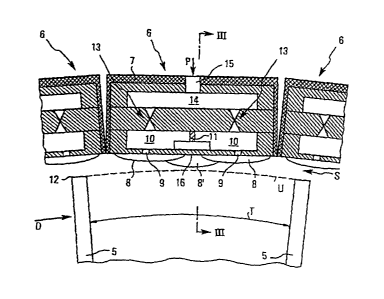
Fig. 2 diagrammatically depicts a cross section on line
II-II from Fig. 1. This cross section lies in the
region of a rotor disk RV which forms a compressor
stage upstream of a combustion chamber B of the
aircraft engine.
As can be seen from Fig. 2, the rotor R~ of the
compressor stage has rotor blades 5 which are arranged
at a predetermined distance T from one another. The
rotor blades rotate in the direction of rotation D. On
the housing side, the rotor blades 5 are surrounded by
a ring of rotor gap control modules 6. The rotor gap
control module is illustrated on an enlarged scale
compared to the rotor and the rotor gap in Fig. 2, and
also in the remaining figures, in order to clarify the
illustration. Typical sizes of the dimensions of the
rotor gap control module are between 0.5 and SO mm,
preferably around 10 to 20 mm.
By way of example, the structure of a rotor gap control
module 6 will now be explained with reference to the
CA 02442749 2003-09-29
P036 728/W0/1
- 20 -
middle rotor gap control module shown in Fig. 2.
The rotor gap control module 6 has a housing 7 which
surrounds the rotor gap control module 6 on all sides
apart from the side facing the rotor blades 5. The
housing 7 is made from a thermally insulating and
preferably also oscillation-insulating material. The
rotor gap control module can be handled as an
independent unit on account of the housing 7. To enable
the rotor gap control module 6 to be exchanged for
other modules in a mechanically and electrically simple
way in the event of maintenance being carried out, all
the connections to the housing 7 are of standardized
design.
That part of the rotor gap control module which is
surrounded by the housing 7 is made from a
microstructural system made from silicon or a silicon
compound, such as silicon nitride or silicon carbide.
Standard microstructural technology processes, such as
lithography followed by electroforming and demolding,
micromachining, etching operations, etc. can be used to
produce it.
The rotor blade control module 6 has sealing elements 8
which are designed in such a way as to project into the
rotor gap S in an operating position. As seen in the
direction of rotation D of the rotor 5, the sealing
elements 8 are significantly smaller than the distance
T between two rotor blades. The sealing elements 8 are
formed from a thin diaphragm made from silicon or a
silicon-containing material, such as silicon carbide,
and are each connected to an actuator chamber 10 via at
least one pressure line 9. The wall thickness of the
diaphragm is such that the diaphragm has a high
elasticity. The actuator chambers 10 of the
corresponding sealing element 8 are separated from one
another by a wall 11 in the exemplary embodiment shown
CA 02442749 2003-09-29
P036 728/W0/1
- 21 -
in Fig. 2. Assigning the minimum possible number of
sealing elements 8 to one actuator chamber 10 allows
the sealing elements 8 to be actuated more accurately.
The sealing elements 8 together do not form a
continuous sealing surface corresponding to the
rotational path U of the rotor blade tips 12, but
rather form discrete sealing surfaces which are spaced
apart from one another and interact with the rotor
blade tips as mating sealing surfaces. As can be seen
from Fig. 2, the sealing elements 8 are arranged
staggered in a plurality of rows, so that the space 8
between two sealing elements belonging to one row is
covered by a sealing element 8' belonging to another
row.
The actuator chamber 10 of a respective sealing element
8 is connected to a pressure chamber 14 via a valve 13.
The actuator chamber 10, the pressure chamber 14 and
the valve 13 are parts of a pneumatic actuator unit,
i.e. an actuator unit operated by compressed air, of
the rotor gap control module, which is used to actively
adjust the sealing element 8. In this context, an
active adjustment is to be understood as meaning an
adjustment for which energy from outside the
turbomachine or from other areas of the turbomachine is
used.
When the rotor gap control module is manufactured using
microstructural technology (MEMS, micro-electro-
mechanical systems), the valves 13 are microvalves
which are produced integrally with the rotor gap
control module.
The valves 13, in response to a signal, open the
connection between in each case one actuator chamber 10
and the pressure chamber 14, so that the pressure
prevailing in the corresponding pressure chamber 14
CA 02442749 2003-09-29
P036 728/W0/1
- 22 -
propagates into the actuator chamber 10.
The pressure chamber 14 is connected via a line 15 to a
pressure source which is acted on by a pressure P. The
housing 7 has a standardized connection element, so
that a pressure line can be connected to the line 15
without the need for special means.
As can be seen from Fig. 2, on account of the small
size of the microstructural elements it is not
necessary for their surface 16 which faces the rotor
gap S to be formed in the shape of a segment of a
circle. On account of the small overall size of the
rotor blade control modules in the direction of
rotation, good closeness to the rotational path U of
the rotor blade tips 12 is achieved even at low
production costs. However, it is possible for the
surface 16 to be configured in the form of a segment of
a circle.
Fig. 2 also shows the modular nature of the rotor gap
control module. The rotor gap control module in each
case forms a structural unit which is substantially
independent and can easily be exchanged, at low cost,
for modules of a similar type.
Fig. 3 shows a section on line III-III from Fig. 2,
i.e. a section running in an axial direction A through
a rotor gap control module.
It can be seen from Fig. 3 that in the main direction
of flow H the dimensions of the sealing elements are
also significantly smaller than the component C of the
chord of the rotor blade 5. The sealing elements 8 form
an array which overall leads to good sealing of the
rotor gap S. A rotor blade tip 12, as mating sealing
surface, is in each case assigned a plurality of
sealing elements as it rotates.
CA 02442749 2003-09-29
P036 728/W0/1
- 23 -
As can be seen from Fig. 3, in each case two sealing
elements 8, which are arranged one behind the other in
the main direction of flow H, are connected to an
actuator chamber 10. Each of these actuator chambers is
connected to the pressure chamber 14 via a microvalve
13.
Fig. 3 illustrates the diaphragms of the sealing
elements 8 in positions extended to different degrees
into the rotor gap S. These positions do not correspond
to an actual operating state, but rather serve merely
to illustrate the movement of the sealing elements 8
which is produced as a result of the elastic diaphragm
being inflated in bubble form.
As can be seen from Fig. 2, the rows of sealing
elements 8 or sealing bubbles are in a staggered
arrangement, so that a flow which is directed through
the array of sealing elements 8 encounters a very high
flow resistance which forms the basis of the sealing
action of the sealing elements. To increase the sealing
action, it is also possible for there to be a plurality
of rings of rotor gap control modules. These rings can
be offset relative to one another in the
circumferential direction, so that the rotor gap
control module of one ring covers the gap between two
rotor gap control modules belonging to the other ring.
As can also be seen from Fig. 3, the housing 7 forms
securing sections 17 which can be connected to
corresponding sections of the housing 18 of the
turbomachine. That surface 16 of the rotor gap control
element 6 which faces the rotor gap 5 preferably ends
flush with the housing element 18, without any gaps.
To enable the rotor gap control module 6 to form an
independent unit which can adjust the rotor gap
CA 02442749 2003-09-29
P036 728/W0/1
- 24 -
independently of the other rotor gap control modules of
the ring around the rotor RV, the rotor gap control
module 6 is provided with a control unit 19 and a
sensor unit 20, which are only diagrammatically
indicated in Fig. 3. The sensor unit 20 has a pressure
sensor (not shown) for recording the pressure in the
rotor gap, a further pressure sensor (not shown) for
recording the pressure in the actuator chamber and a
gap-measuring sensor (not shown), which can be used to
measure the size of the rotor gap S. The gap-measuring
sensor can operate on an optical or capacitive basis,
preferably without contact.
Furthermore, an oscillation sensor (not shown), which
uses optical, capacitive or acoustic (ultrasound) means
to record the oscillations of the rotor blades R and/or
of the rotor blade tips 5, is integrated in the sensor
unit 20. Alternatively, it is also possible to provide
oscillation sensors for recording housing oscillations,
hub or shaft oscillations and oscillations of the
sealing element itself.
The sensor unit 20 is provided with an output
interface, via which the respective sensors output
signals which are representative of the measured
variables which they have recorded via a data line 21.
The data line 21 is connected to an input interface of
the control unit 19. The control unit 19 processes the
data received from the sensor unit 20 and, via an
output interface, outputs output data, as a function of
the input data and data stored in a memory, to an
output line 22. The output line 22 is connected to the
valves 13 of the actuator unit . The valves 13 open and
close in response to a corresponding signal from the
output line 22.
An internal energy source 22, in the form of a means
for generating current, may be provided in the rotor
CA 02442749 2003-09-29
P036 728/Vd0/1
- 25 -
gap control module for the purpose of supplying the
control unit 21 and the sensor unit 20 and also the
microvalves 13. As illustrated in Fig. 3, this means
may be designed in the form of a coil which generates
energy by means of an externally applied magnetic
field.
The control unit 20 also has a databus 23, which leads
to the outer side 7 of the housing, so that a
connection to external control elements and to other
rotor gap control modules can be made via the bus . The
data lines 21 and 22 and also the databus 23 may also
be part of a continuous databus which connects all
components of the rotor blade control module to one
another. The energy source, the actuator unit with the
microvalves, the control unit 19 and the sensor unit 20
may all form elements of a rotor gap control module
which is constructed as a single-piece microsystem and
can be formed substantially simultaneously during a
single production step.
The databus may also be designed as a radio
transmission link (not shown), in which the data are
transmitted to a receiving station without contact in
the form of electromagnetic waves. In this case, a
transmission unit is integrated in the control unit. To
allow bidirectional data flow via the radio
transmission link, the control unit 20 is provided with
a radio receiver.
Figure 4 illustrates an axial section through a further
exemplary embodiment of a rotor gap control module
according to the invention.
The text which follows will only deal with the
differences with respect to the first exemplary
embodiment as illustrated, for example, in Fig. 3, for
the sake of simplicity. This description will use the
CA 02442749 2003-09-29
P036 728/W0/1
- 26 -
same reference numerals for components which are
identical to those presented in the previous exemplary
embodiments.
Unlike in the first exemplary embodiment, the rotor gap
control module 6 shown in Fig. 4 has two pressure
chambers 24, 25, one pressure chamber 24 being an
excess-pressure chamber, which is acted on by a
pressure P1, and the chamber 25 being a reduced-
pressure chamber, which is acted on by a reduced
pressure P2. The pressure P1 is greater than the
pressure PR in the region of the rotor gap. The
pressure Pz is lower than the pressure PR. In the
exemplary embodiment shown in Fig. 4, the excess-
pressure chamber 24 and the reduced-pressure chamber 25
are each connected to the actuator chamber 10 by means
of two microvalves 13. The provision of two valves
allows rapid pressure equalization between in each case
the actuator chamber 10 and the excess-pressure or
reduced-pressure chamber 24, 25.
The excess-pressure chamber 24 is connected to a region
of the turbomachine in which, when the turbomachine is
operating, the pressure is higher than in the region of
the rotor gap. The reduced-pressure chamber 25, by
contrast, is connected to a region of the turbomachine
which, when the turbomachine is operating normally, is
acted on by a pressure which is lower than the pressure
in the region of the rotor gap.
Independently of the structure having the two pressure
chambers, Fig. 4 also illustrates a further possible
way of generating energy within the rotor gap control
module.
The excess-pressure chamber 24 is connected to the
reduced-pressure chamber 25 via a microturbine 30,
which may likewise be designed using microstructural
CA 02442749 2003-09-29
P036 728/W0/1
- 27 -
technology. The microturbine 30 implements a constant
equalizing flow between the excess-pressure chamber 24
and the reduced-pressure chamber 25, which drives the
microturbine and contributes to the generation of
energy for the control unit 19, the sensor unit 20 and
the microvalves 13 or is solely responsible for
supplying energy to the rotor gap control module. To
generate energy, the microturbine 30 may be provided
with a magnetic rotor 31, which generates current via a
coil 32. This aspect of energy generation is also
advantageous independently of the use of the rotor gap
control module 6.
The equalizing flow through the microturbine 30 is so
slight that the efficiency of the turbomachine is not
affected.
Fig. 5 shows a third exemplary embodiment of a rotor
gap control module according to the invention. For the
sake of simplicity, once again only the differences
with respect to the previous exemplary embodiments will
be dealt with in detail, and identical reference
numerals are used for components which are identical to
those shown in the previous exemplary embodiments.
A first difference between the third exemplary
embodiment and the previous exemplary embodiments
consists in the fact that a plurality of sealing
elements 8 are in each case surrounded by a casing 35
which consists of a material which is resistant to
abrasion. The casing 35 protects the sealing elements 8
from contact with the rotor blade tip 12.
Irrespective of the casing 35, a further difference
between the third exemplary embodiment and the previous
exemplary embodiments consists in the arrangement of
the pressure chambers 24, 25.
CA 02442749 2003-09-29
P036 728/V~10/1
- 28 -
Since the excess-pressure chamber 25 is usually acted
on by a warmer fluid than the reduced-pressure chamber
24, temperature equalization is achieved by arranging
the excess-pressure chamber 25 inside the reduced
pressure chamber 24.
The reduced-pressure chamber 24 surrounds the excess-
pressure chamber 25 at least in sections, so that the
rotor gap control module does not overheat. The rotor
gap control module 6 shown in Fig. 5 also does not have
a housing 7, but rather is constructed as a
microstructural block which is already in the
corresponding standardized form.
The text which follows describes the function of the
rotor gap control module according to the invention on
the basis of the exemplary embodiment illustrated in
Fig. 2:
The gap sensor of the sensor unit 19 measures the size
of the rotor gap between the rotor gap tip 12 and the
sealing elements 8 and transmits the measured value via
the data line 21 to the control unit 19. The control
unit 19 compares this measured value with threshold
values which have been programmed in and, as a function
of this comparison, outputs an output signal via the
data line 22 to the actuator unit having the
microvalves 13. The threshold values may be stored in
fixed form in the control unit 19 or may be constantly
updated via the databus 23 as a function of the
operating time.
If the size of the rotor gap falls below a
predetermined lower threshold value, this means that
the rotor gap is too small, and accordingly the sealing
elements 8 need to be moved out of the rotor gap. For
this purpose, the control unit 19 emits signals to the
microvalves 13 which connect the reduced-pressure
CA 02442749 2003-09-29
P036 728/W0/1
- 29 -
chamber 24 to the actuator chamber 10. The air flows
out of the actuator chamber, since the pressure in the
chamber drops. The diaphragm of the sealing element 8
contracts, so that the size of the rotor gap S
increases. For more accurate control, it is also
possible for a plurality of threshold values to be
stored in the control unit 19, which threshold values,
in one refinement, are used to set the optimum rotor
gap as a function of the operating parameters currently
prevailing in the turbomachine.
The sensor unit 20 continuously monitors the pressure
in the actuator chamber and the size of the rotor gap.
If a comparison by the control unit 19 establishes that
the predetermined rotor gap width has been reached, the
opened microvalve 13 is closed again and the pressure
in the actuator chamber is kept constant.
On the other hand, if the value for the rotor gap
measured by the gap sensor is higher than a
predetermined threshold value, this means that the
rotor gap S is too large. Consequently, the control
unit 19 opens the microvalves 13 which connect the
actuator chamber 10 to the excess-pressure chamber 25.
This causes the pressure in the actuator chamber 10 to
increase and the diaphragms of the sealing elements to
widen out under the influence of pressure, forming a
sealing bubble. The sealing elements extend toward the
rotor gap and reduce the size of the gap. If the
measured value of the rotor gap is once again within
the two threshold values, the open valve is closed
again.
The upper threshold value may, for example, lie in the
range between 0.3 and 2 mm, while the lower threshold
value may lie in the range between 0.1 and 0.7 mm.
By monitoring the pressure in the actuator chamber 10,
CA 02442749 2003-09-29
P036 728jWOj1
- 30 -
the control unit 19 can be used to output an error
signal. If the pressure of the actuator chamber 10
constantly corresponds to the pressure PR in the region
of the rotor, a leak is present and the element needs
to be exchanged.
This method is used by the rotor gap control module to
control the size of the rotor gap S automatically to an
optimum value under differing operating conditions. The
logic elements provided in the control unit 19 are
preferably limited to simple comparison arithmetic, so
that the control unit is of simple structure and the
control algorithms can be performed quickly.
The integration of control unit, sensor unit and energy
source in the rotor gap control module results in the
rotor gap being controlled completely independently by
an exchangeable module.
This functionality is supplemented by the possibility
of monitoring components of the turbomachine using
further sensors, such as for example the oscillation
sensor. This on the one hand allows the operating state
of the turbomachine to be monitored during operation,
in order to provide advance warning of component
failures or to indicate that maintenance work is due.
On the other hand, in this refinement it is also
possible for operation of the turbomachine to be
optimized by evaluating the results.
A plurality of rotor gap modules can be linked to one
another by data lines, so that synchronized actuation
of a plurality of rotor gap control modules is also
achieved and the data of an individual rotor gap
control module can be made available to further modules
in order to make the control more precise.
The simple control logic and the small moving masses of
CA 02442749 2003-09-29
P036 728/W0/1
- 31 -
the rotor gap control modules according to the
invention allow a response performance which is in the
region of the blade passing frequency of the rotor, so
that it is possible to match the rotor gap to
individual rotor blades.
Figures 6 and 7 show a further possible application of
the rotor gap control modules in one of the above
configurations as a shaft sealing module.
Figure 6 shows an axial section through the shaft and
the sealing modules.
As with the rotor gap control module, it is also
possible for a plurality of rows of rotor gap control
modules to be arranged behind one another for use as a
shaft sealing module. The only difference with respect
to the rotor gap control module consists in the fact
that in this application the mating sealing surface is
substantially continuous.
The staggered arrangement of the sealing elements 8
means that a good seal can be achieved with respect to
the shaft surface 40.
To achieve sealing even in the transition region
between two sealing modules which follow one another in
the circumferential direction, the sealing modules are
arranged in staggered form, so that in each case one
sealing element 8' ' belonging to one row is located in
the region between two sealing modules 6 belonging to
another row.
If an abrasion-resistant material is used for the
sealing elements 8, it is also possible for the sealing
elements 8 to be in direct contact with the shaft
surface 40. The inflation pressure in the diaphragm in
this way controls the force with which the sealing
CA 02442749 2003-09-29
P036 728/W0/1
- 32 -
elements are pressed onto the mating sealing surface.
Figure 7 shows a shaft sealing module having the
structure of the rotor gap control module shown in
Fig. 5 in axial section on line VII-VII in Fig. 6.
As can be seen from Fig. 7, the shaft forms a sealing
shoulder 41, on which two rows of sealing modules,
which are combined to form a closed ring and are
designed analogously to a rotor gap control module, are
formed. In this case too, the sealing surface comprises
a multiplicity of discrete surfaces, and the sealing
action is based on an increase in the flow resistance
as fluid particles move through the sealing elements.
The rapid response time of the sealing modules allows a
good sealing action to be achieved even in the event of
eccentricity or bending oscillations on the part of the
shaft, since the sealing elements, as described above
with reference to the example of the rotor gap control,
react immediately to a shaft movement and therefore to
a change in the sealing gap.