Note: Descriptions are shown in the official language in which they were submitted.
CA 02442960 2010-02-26 -.
-I
VESSEL SEALING INSTRUMENT
BACKGROUND
The present disclosure relates to forceps used for open surgical
procedures. More particularly, the present disclosure relates to a forceps
which
applies a combination of mechanical clamping pressure and electrosurgical
current to seal tissue.
Technical Field
A hemostat or forceps is a simple plier-like tool which uses
mechanical action between its jaws to constrict vessels and is commonly used
in
open surgical procedures to grasp, dissect and/or clamp tissue.
Electrosurgical
forceps utilize both mechanical clamping action and electrical energy to
effect
I
CA 02442960 2003-10-03
WO 02/080797 PCT/USO1/11420
hemostasis by heating the tissue and blood vessels to coagulate, cauterize
and/or
seal tissue.
Certain surgical procedures require sealing and cutting blood
vessels or vascular tissue. Several journal articles have disclosed methods
for
sealing small blood vessels using electrosurgery. An article entitled Studies
on
Coagulation and the Development of an Automatic Computerized Bipolar
Coagulator, J. Neurosurg., Volume 75, July 1991, describes a bipolar
coagulator
which is used to seal small blood vessels. The article states that it is not
possible
to safely coagulate arteries with a diameter larger than 2 to 2.5 mm. A second
article is entitled Automaticall Controlled Bipolar Electrocoagulation - "COA-
COMP", Neurosurg. Rev. (1984), pp. 187-190, describes a method for terminating
electrosurgical power to the vessel so that charring of the vessel walls can
be
avoided.
By utilizing an electrosurgical forceps, a surgeon can either
cauterize, coagulate/desiccate, reduce or slow bleeding and/or seal vessels by
controlling the intensity, frequency and duration of the electrosurgical
energy
applied to the tissue. Generally, the electrical configuration of
electrosurgical
forceps can be categorized in two classifications: 1) monopolar
electrosurgical
forceps; and 2) bipolar electrosurgical forceps.
2
CA 02442960 2003-10-03
WO 02/080797 PCT/US01/11420
Monopolar forceps utilize one active electrode associated with the
clamping end effector and a remote patient return electrode or pad which is
typically attached externally to the patient. When the electrosurgical energy
is
applied, the energy travels from the active electrode, to the surgical site,
through
the patient and to the return electrode.
Bipolar electrosurgical forceps utilize two generally opposing
electrodes which are disposed on the inner opposing surfaces of the end
effectors
and which are both electrically coupled to an electrosurgical generator. Each
electrode is charged to a different electric potential. Since tissue is a
conductor of
electrical energy, when the effectors are utilized to grasp tissue
therebetween, the
electrical energy can be selectively transferred through the tissue.
In order to effect a proper seal with larger vessels, two predominant
mechanical parameters must be accurately controlled - the pressure applied to
the vessel and the gap between the electrodes both of which affect thickness
of
the sealed vessel. More particularly, accurate application of the pressure is
important to oppose the walls of the vessel, to reduce the tissue impedance to
a
low enough value that allows enough electrosurgical energy through the tissue,
to
overcome the forces of expansion during tissue heating and to contribute to
the
end tissue thickness which is an indication of a good seal. It has been
determined that a fused vessel wall is optimum between 0.001 and 0.005 inches.
3
CA 02442960 2003-10-03
WO 02/080797 PCT/US01/11420
Below this range, the seal may shred or tear and above this range the lumens
may not be properly or effectively sealed.
With respect to smaller vessel, the pressure applied to the tissue
tends to become less relevant whereas the gap distance between the
electrically
conductive surfaces becomes more significant for effective sealing. In other
words, the chances of the two electrically conductive surfaces touching during
activation increases as the vessels become smaller.
Electrosurgical methods may be able to seal larger vessels using an
appropriate electrosurgical power curve, coupled with an instrument capable of
applying a large closure force to the vessel walls. It is thought that the
process of
coagulating small vessels is fundamentally different than electrosurgical
vessel
sealing. For the purposes herein, "coagulation" is defined as a process of
desiccating tissue wherein the tissue cells are ruptured and dried and vessel
sealing is defined as the process of liquefying the collagen in the tissue so
that it
reforms into a fused mass. Thus, coagulation of small vessels is sufficient to
permanently close them. Larger vessels need to be sealed to assure permanent
closure.
Numerous bipolar electrosurgical forceps have been proposed in the
past for various open surgical procedures. However, some of these designs may
not provide uniformly reproducible pressure to the blood vessel and may result
in
4
CA 02442960 2003-10-03
WO 02/080797 PCT/US01/11420
an ineffective or non-uniform seal. For example, U.S. Patent No. 2,176,479 to
Willis, U.S. Patent Nos. 4,005,714 and 4,031,898 to Hiltebrandt, U.S. Patent
Nos.
5,827,274, 5,290,287 and 5,312,433 to Boebel et at., U.S. Patent Nos.
4,370,980,
4,552,143, 5,026,370 and 5,116,332 to Lottick, U.S. Patent No. 5,443,463 to
Stern et al., U.S. Patent No. 5,484,436 to Eggers et al. and U.S. Patent No.
5,951,549 to Richardson et at., all relate to electrosurgical instruments for
coagulating, cutting and/or sealing vessels or tissue.
Many of these instruments include blade members or shearing
members which simply cut tissue in a mechanical and/or electromechanical
manner and are relatively ineffective for vessel sealing purposes. Other
instruments rely on clamping pressure alone to procure proper sealing
thickness
and are not designed to take into account gap tolerances and/or parallelism
and
flatness requirements which are parameters which, if properly controlled, can
assure a consistent and effective tissue seal. For example, it is known that
it is
difficult to adequately control thickness of the resulting sealed tissue by
controlling
clamping pressure alone for either of two reasons: 1) if too much force is
applied,
there is a possibility that the two poles will touch and energy will not be
transferred through the tissue resulting in an ineffective seal; or 2) if too
low a
force is applied, a thicker less reliable seal is created.
As mentioned above, in order to properly and effectively seal larger
vessels, a greater closure force between opposing jaw members is required. It
is
CA 02442960 2003-10-03
WO 02/080797 PCT/US01/11420
known that a large closure force between the jaws typically requires a large
moment about the pivot for each jaw. This presents a challenge because the jaw
members are typically affixed with pins which are positioned to have a small
moment arms with respect to the pivot of each jaw member. A large force,
coupled with a small moment arm, is undesirable because the large forces may
shear the pins. As a result, designers must compensate for these large closure
forces by either designing instruments with metal pins and/or by designing
instruments which at least partially offload these closure forces to reduce
the
chances of mechanical failure. As can be appreciated, if metal pivot pins are
employed, the metal pins must be insulated to avoid the pin acting as an
alternate
current path between the jaw members which may prove detrimental to effective
sealing.
Increasing the closure forces between electrodes may have other
undesirable effects, e.g., it may cause the opposing electrodes to come into
close
contact with one another which may result in a short circuit and a small
closure
force may cause pre-mature movement of the issue during compression and prior
to activation.
Thus, a need exists to develop a bipolar forceps which effectively
seals vascular tissue and solves the aforementioned problems by providing an
instrument which enables a large closure force between the opposing jaws
members, reduces the chances of short circuiting the opposing jaws during
6
CA 02442960 2003-10-03
WO 02/080797 PCT/US01/11420
activation and assists in manipulating, gripping and holding the tissue prior
to and
during activation.
SUMMARY
The present disclosure relates to a bipolar electrosurgical instrument
for use in open surgery which includes first and second shafts one of which is
connectable to a source of electrosurgical energy. Each shaft includes a jaw
member extending from a distal end thereof and a handle disposed at a proximal
end thereof for effecting movement of the jaw members relative to one another
from a first, open position wherein the jaw members are disposed in spaced
relation relative to one another to a second, closed position wherein the jaw
members cooperate to grasp tissue therebetween. The source of electrical
energy effects first and second electrical potentials in the respective jaw
members
such that the jaw members are capable of selectively conducting energy through
tissue held therebetween to effect a seal.
Preferably, the first and second electrical potentials are created at
the jaw members through the first shaft. For example, in one embodiment, the
first electrical potential is transmitted through the first shaft by a lead
having a
terminal end which electrically interfaces with a distal connector which
connects a
first jaw member to the first electrical potential. The second electrical
potential is
7
CA 02442960 2003-10-03
WO 02/080797 PCT/US01/11420
transmitted through the first shaft by a tube disposed within the first shaft
which
connects the second jaw member to the second electrical potential.
The first and second jaw members are connected about a pivot pin.
The distal connector is preferably interposed between the jaw members and
includes a series of flanges which are dimensioned to prevent the emanation of
stray currents from the electrically conductive sealing surfaces of the jaw
members during activation.
Preferably, the distal connector includes a spring washer or wave
washer which acts as an electrical intermediary between the terminal end and
the
jaw member. In one embodiment, the spring washer is beveled to enhance the
electrical interface between the terminal end and the jaw member, i.e.,
beveling
causes the spring washer to rotate relative the terminal end during movement
of
the jaw members from the first to second positions which provides a self-
cleaning,
enhanced running electrical contact between the terminal end and the jaw
member.
Preferably, the distal connector is made from an insulative substrate
and is disposed between the jaw members for electrically isolating the first
and
second potentials. In one embodiment, the distal connector includes a first
surface having at least one recess defined therein which is dimensioned to
receive at least a portion of the terminal end of the lead.
8
CA 02442960 2003-10-03
WO 02/080797 PCT/US01/11420
In yet another embodiment, one of the jaw members includes a skirt
which is dimensioned to prevent exposure of the terminal end during all angles
of
operation, i.e., when the jaw members are disposed in the first position, the
second position and/or during operative movement therebetween.
The lead preferably includes a inner core made from a solid or multi-
strand electrically conductive material, e.g., copper/aluminum wire, which is
surrounded by an insulative, non-conductive coating, e.g., plastic. In one
embodiment, the terminal or distal end of the electrically conductive material
is
flattened, i.e., "flat-formed", and is dimensioned to substantially encircle a
boss
which extends from the surface of the distal connector. Preferably, the boss
is
designed to electrically insulate the terminal end of the lead from the pivot
pin.
In another embodiment, at least one non-conductive stop member is
disposed on an electrically conductive sealing surface of one of the jaw
members.
The stop members are designed to control/regulate the distance, i.e., gap,
between the jaw members when tissue is held therebetween during activation
BRIEF DESCRIPTION OF THE DRAWINGS
Various embodiments of the subject instrument are described herein
with reference to the drawings wherein:
9
CA 02442960 2003-10-03
WO 02/080797 PCT/US01/11420
Fig. 1 is a left, perspective view of a forceps according to the
present disclosure;
Fig. 2 is an enlarged, perspective view of an end effector assembly
of the forceps of Fig. 1 shown in open configuration;
Fig. 3 is an enlarged, perspective view of the end effector assembly
of the forceps of Fig. I shown in closed configuration;
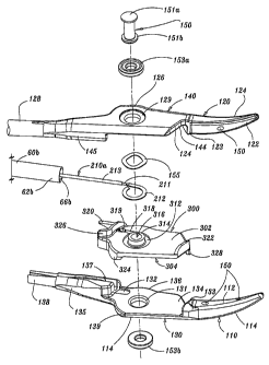
Fig. 4A is an exploded view of the forceps according to the present
disclosure;
Fig. 4B is an enlarged, exploded view of the end effector assembly
of Fig. 4A showing the electrical connection of a distal electrical connector
for
supplying electrical energy to the end effector assembly;
Fig. 5 is an enlarged, top perspective view of a lower jaw member of
forceps with the distal connector seated thereon;
Fig. 6 is a right, perspective view of the forceps of Fig. 1 shown
grasping a tissue structure;
CA 02442960 2003-10-03
WO 02/080797 PCT/US01/11420
Fig. 7 is a enlarged view of the indicated area of detail in Fig. 4A
showing a proximal electrical interface/connector for supplying electrical
energy to
the end effector assembly; and
Fig. 8 is a cross section of the forceps of Fig. 6 showing the
electrical feed path of a first lead having a first electrical potential and
showing the
electrical connection of the proximal electrical interface of Fig. 7 with a
second
lead having a second electrical potential.
DETAILED DESCRIPTION
Referring now to Figs. 1-4, a forceps 10 for use with open surgical
procedures includes elongated shaft portions 12a and 12b each having a
proximal end 16a and 16b, respectively, and a distal end 14a and 14b,
respectively. In the drawings and in the descriptions which follow, the term
"proximal", as is traditional, will refer to the end of the forceps 10 which
is closer to
the user, while the term "distal" will refer to the end which is further from
the user.
The forceps 10 includes an end effector assembly 100 which
attaches to distal ends 14a and 14b of shafts 12a and 12b, respectively. As
explained in more detail below, the end effector assembly 100 includes pair of
opposing jaw members 110 and 120 which are pivotably connected about a pivot
pin 150.
11
CA 02442960 2003-10-03
WO 02/080797 PCT/US01/11420
Preferably, each shaft 12a and 12b includes a handle 17a and 17b
disposed at the proximal end 16a and 16b thereof which each define a finger
hole
18a and 18b, respectively, therethrough for receiving a finger of the user. As
can
be appreciated, finger holes 18a and 18b facilitate movement of the shafts 12a
and 12b relative to one another which, in turn, pivot the jaw members 110 and
120 from an open position (Fig. 2) wherein the jaw members 110 and 120 are
disposed in spaced relation relative to one another to a clamping or closed
position (Fig. 3) wherein the jaw members 110 and 120 cooperate to grasp
tissue
400 (Fig. 6) therebetween.
A ratchet 30 is preferably included for selectively locking the jaw
members 110 and 120 relative to one another at various positions during
pivoting.
As best shown in Fig. 6, a first ratchet interface, e.g., 30a, extends from
the
proximal end 16a of shaft member 12a towards a second ratchet interface 30b in
a generally vertically aligned manner such that the inner facing surfaces of
each
ratchet 30a and 30b abut one another upon closure about the tissue 400.
Preferably, each ratchet interface 30a and 30b includes a plurality of flanges
32a
and 32b, respectively, which projects from the inner facing surface of each
ratchet
interface 30a and 30b such that the ratchet interfaces 30a and 30b interlock
in at
least one position. In the embodiment shown in Fig. 6, the ratchet interfaces
30a
and 30b interlock at several different positions.
12
CA 02442960 2003-10-03
WO 02/080797 PCT/US01/11420
Preferably, each position associated with the cooperating ratchet
interfaces 30a and 30b holds a specific, i.e., constant, strain energy in the
shaft
members 12a and 12b which, in turn, transmits a specific closing force to the
jaw
members 110 and 120. It is envisioned that the ratchet 30 may include
graduations or other visual markings which enable the user to easily and
quickly
ascertain and control the amount of closure force desired between the jaw
members. A design without a ratchet system or similar system would require the
user to hold the jaw members 110 and 120 together by applying constant force
to
the handles 17a and 17b which may yield inconsistent results.
As best illustrated in Fig. 1, one of the shafts, e.g., 12b, includes a
proximal shaft connector 19 which is designed to connect the forceps 10 to a
source of electrosurgical energy such as an electrosurgical generator (not
shown). More particularly, proximal shaft connector 19 is formed by a cover
19a
and a flange 19b which extends proximally from shaft 12b. Preferably, cover
19a
and flange 19b mechanically cooperate to secure an electrosurgical cable 210
to
the forceps 10 such that the user may selectively apply electrosurgical energy
as
needed.
The proximal end of the cable 210 includes a plug 200 having a pair
of prongs 202a and 202b which are dimensioned to electrically and mechanically
engage the electrosurgical energy generator. As explained in more detail below
with respect to Fig. 8, the distal end of the cable 210 is secured to the
proximal
13
CA 02442960 2003-10-03
WO 02/080797 PCT/US01/11420
shaft connector 19 of shaft 12b by a plurality of finger-like clamping members
77a
and 77b and a cable crimp having opposing fingers 76a and 76b. The interior of
cable 210 houses a pair of leads 210a and 210b which conduct the different
electrical potentials from the electrosurgical generator to the jaw members
110
and 120 as explained in greater detail below.
As best seen in Figs. 2 - 4B, the two opposing jaw members 110
and 120 of the end effector assembly 100 are pivotable about pin 150 from the
open position to the closed position for grasping tissue 400 therebetween. Jaw
members 110 and 120 are generally symmetrical and include similar component
features which cooperate to permit facile rotation about pivot pin 150 to
effect the
grasping and sealing of tissue 400. As a result and unless otherwise noted,
jaw
member 110 and the operative features associated therewith will initially be
described herein in detail and the similar component features with respect to
jaw
member 120 will be briefly summarized thereafter.
Jaw member 110 includes an insulated outer housing 114 which is
dimensioned to mechanically engage an electrically conductive sealing surface
112 and a proximally extending flange 130 which is dimensioned to seat a
distal
connector 300 which is described in more detail below with respect to Figs.
4A,
4B and 5. Preferably, outer insulative housing 114 extends along the entire
length of jaw member 110 to reduce alternate or stray current paths during
sealing and/or incidental burning of tissue 400. The inner facing surface of
14
CA 02442960 2010-02-26
WO 02/080797 PCT/USO1/11420
flange 130 includes an electrically conductive plate 134 (Fig. 4B) which
conducts
electrosurgical energy to the electrically conductive sealing surface 112 upon
activation.
Likewise, jaw member 120 include similar elements which include:
an outer housing 124 which engages an electrically conductive sealing surface
122; a proximally extending flange 140 which seats the opposite face of the
distal
connector 300; an electrically conductive plate 144 which conducts
electrosurgical
energy to the electrically conductive sealing surface 122 upon activation.
It is envisioned that one of the jaw members, e.g., 110, includes at
least one stop member 150 disposed on the inner facing surface of the
electrically
conductive sealing surface 112 (and/or 122). The stop member(s) is preferably
designed to facilitate gripping and manipulation of tissue 400 and to define a
gap
"G" (Fig. 6) between opposing jaw members 110 and 120 during sealing. A
detailed discussion of these and other envisioned stop members 150 as well as
various manufacturing and assembling processes for attaching, disposing,
depositing and/or affixing the stop members 150 to the electrically conductive
sealing surfaces 112, 122 are described in WO 0207627
published January 31, 2002.
CA 02442960 2003-10-03
WO 02/080797 PCT/US01/11420
Fig. 4A shows an exploded view of the various components of the
forceps 10 and the inter-operative relationships among the same. More
particularly and in addition to the components described above with respect to
Figs. 1-3 above, shaft 12a is preferably hollow to define a longitudinal
channel
15a disposed therethrough which is dimensioned to receive a tube 60a therein.
Tube 60a includes a proximal end 64a, a distal end 62a and at least one
mechanical interface 61a disposed therebetween. Shaft 12a also includes a
cover plate 50 which is designed for snap-fit engagement within an
aperture/cavity 45a defined through the outer surface of shaft 12a. Cover
plate
50 includes a series of opposing flanges 51 a and 51 b which extend therefrom
which are dimensioned to secure the tube 60a within shaft 12a as described
below. A second flange 52 secures the cover plate 50 to the shaft 12a.
During assembly, the proximal end 64a of tube 60a is slideable
incorporated within channel 15a such that mechanical interface 61a is poised
for
engagement with cover plate 50. Cover plate 50 is then snapped into cavity 45a
such that flanges 51a and 51b secure tube 60a within shaft 12a. It is
envisioned
that the cavity 45a of shaft 12a may include at least one detent (not shown)
which
engages mechanical interface 61 a disposed along the outer surface of tube 60a
to limit / prevent rotation of the tube 60a relative to the shaft 12a. This
cooperative relationship is shown by way of example with respect to detents
75a
and 75b and interfaces (e.g., notches) 61b of shaft 12b in Fig. 8. In this
instance,
flanges 51 a and 51 b (much like flanges 42a and 42b of cover plate 40 in Fig.
8)
16
CA 02442960 2003-10-03
WO 02/080797 PCT/US01/11420
hold the detents 75a and 75b in Fig. 8) in secure engagement within the
notch(es) 61a to prevent rotational and/or longitudinal movement of the tube
60a
within the channel 15a.
Preferably, the proximal-most end of tube 60a includes a slit-like
interface 65a which mechanically engages a corresponding tongue 88a extending
from the inner surface of shaft 12a within cavity 45a. It is envisioned that
tongue
88a also prevents rotational movement of the tube 60a within the shaft 12a.
Alternatively, slit 65a may be formed to allow radial contraction and
expansion of
the tube 60a to promote friction-fit engagement between the tube 60a and the
shaft 12a. Other interfaces are also envisioned which will facilitate
engagement
of the shaft 12a and the tube 60a, e.g., snap-fit, spring-lock, locking tabs,
screw-
like interface, tongue and groove, etc.
The distal end 62a of tube 60a is preferably dimensioned to engage
jaw member 120, i.e., the distal end 62a includes a slit-like interface 66a
which
promotes simple, secure friction-fit engagement of the tube 60a with the jaw
member 120. More particularly and as mentioned above, jaw member 120
includes a proximally extending flange 130 having a sleeve 128 extending
proximally therefrom which is dimensioned such that, upon insertion of the
sleeve
128 within distal end 62a, slit-like interface 66a expands radially outwardly
and
securely locks the jaw member 120 to tube 60a. Again, other methods of
17
CA 02442960 2003-10-03
WO 02/080797 PCT/US01/11420
attachment are also envisioned which would serve the same purpose, e.g., snap-
locks, locking tabs, spring-locks, screw-like interface, tongue and groove,
etc.
As can be appreciated by the present disclosure, the arrangement
of shaft 12b is slightly different from shaft 12a as shown best in Figs. 4B, 7
and 8.
More particularly, shaft 12b is also hollow to define a channel 15b
therethrough
and is dimensioned to receive a tube 60b therein. Tube 60b includes a proximal
end 64b and a distal end 62b which attach in a generally similar fashion as
their
counterpart components with respect to shaft 12a. For example, the proximal
end
64b of tube 60b is slideable incorporated within channel 15b such that a
mechanical interface 61b disposed on the outer surface of tube 60b is poised
for
engagement with a cover plate 40 (Figs. 4A and 8).
Preferably and since the forceps 10 is uniquely designed to
incorporate all of the electrical interfaces and connections within and along
a
single shaft, e.g., 12b, shaft 12b includes a slightly larger cavity 45b
defined
therein for housing and securing the various electrical connections associated
with the forceps 10 as described below. For example, cover plate 40 is
dimensioned slightly differently than cover plate 50 mostly due to the spatial
considerations which must be taken into account for incorporation of the
various
internally disposed electrical connections. However, cover plate 40 does snap
atop shaft 12b such that a pair of flanges 42a and 42b secure tube 60b within
18
CA 02442960 2003-10-03
WO 02/080797 PCT/US01/11420
shaft 12b in a similar manner as described above. For example, Figure 8 shows
a pair of detents 75a and 75b disposed within the cavity 45b of shaft 12b
which
engage a corresponding number of mechanical interfaces 61 b disposed along the
outer surface of tube 60b to limit / prevent rotation of the tube 60b relative
to the
shaft 12b. When assembled, each flange 42a and 42b is pushed into a
corresponding groove 73a and 73b, respectively, which effectively maintain /
hold
the detents 75a and 75b in secure engagement within the notches 61 b to
prevent
rotational and/or longitudinal movement of the tube 60b within the channel
15b.
End 64b of tube 60b also includes a slit-like interface 65b which
mechanically engages a corresponding tongue 88b extending from the inner
surface of shaft 12b within cavity 45b. It is envisioned that tongue 88a also
prevents rotational movement of the tube 60b within the shaft 12b.
Alternatively,
slit 65b may be formed to allow radial contraction and expansion of the tube
60b
to promote friction-fit engagement between the tube 60b and the shaft 12b.
Unlike tube 60a, tube 60b is designed as an electrical conduit for
transmitting electrosurgical energy to jaw member 110 which is explained in
more
detail below with respect to Figs. 7 and 8. The distal end 62b of tube 60b is
preferably dimensioned to engage jaw member 110, i.e., the distal end 62b
includes a slit-like interface 66b which promotes simple, secure friction-fit
engagement of the tube 60b with the jaw member 110. This is best illustrated
in
Fig. 4B which shows proximally extending flange 130 of jaw member 110 having
19
CA 02442960 2003-10-03
WO 02/080797 PCT/US01/11420
a terminal sleeve 138 which extends therefrom. Terminal sleeve 138 is
dimensioned such that, upon insertion of the terminal sleeve 138 within distal
end
62b, slit-like interface 66b expands radially outwardly and securely locks the
jaw
member 110 to tube 60b.
As can be appreciated, terminal end 138 is at least partially made
from an electrically conductive material such that an electrosurgical
potential is
effectively conducted from the tube 60b, through the terminal sleeve 138,
across
plate 134 and to the electrically conductive sealing plate 112 upon
activation.
As mentioned above, the outer insulative housing 114 of jaw member 110
effectively eliminates stray electrical currents and incidental burning of
tissue
across the intended electrical path.
As best shown in Fig. 4B, jaw member 110 includes a raceway 135
extending proximally from the flange 130 which includes terminal sleeve 138 at
the proximal-most end thereof. The terminal sleeve 138 connects to the
conductive tube 60b disposed within shaft 12b as described above. Raceway
135 serves two purposes: 1) to provide electrical continuity from the terminal
sleeve 138, through the electrically conductive plate 134 and to the
electrically
conductive sealing surface 112; and 2) to provide a channel for guiding lead
210a to the distal connector 300 as described below.
CA 02442960 2003-10-03
WO 02/080797 PCT/US01/11420
Insulated outer housing 114 is dimensioned to securely engage the
electrically conductive sealing surface 112. It is envisioned that this may be
accomplished by stamping, by overmolding, by overmolding a stamped
electrically conductive sealing plate and/or by overmolding a metal injection
molded seal plate. All of these manufacturing techniques produce an electrode
having an electrically conductive surface 112 which is substantially
surrounded by
an insulated outer housing 114.
It is envisioned that the jaw member may also include a second
insulator (not shown) disposed between the electrically conductive sealing
surface 112 and the outer insulative housing 114. The insulated outer housing
114 and the electrically conductive sealing surface 112 (and the other
insulator if
utilized) are preferably dimensioned to limit and/or reduce many of the known
undesirable effects related to tissue sealing, e.g., flashover, thermal spread
and
stray current dissipation.
It is also envisioned that the electrically conductive sealing surface
112 may include a pinch trim (not shown) which facilitates secure engagement
of
the electrically conductive surface 112 to the insulated outer housing 114 and
also simplifies the overall manufacturing process. It is also contemplated
that the
electrically conductive sealing surface 112 may include an outer peripheral
edge
which has a radius and the insulated outer housing 114 meets the electrically
conductive sealing surface 112 along an adjoining edge which is generally
21
CA 02442960 2010-02-26
WO 02/080797 PCT/USO1/11420
tangential to the radius and/or meets along the radius. Preferably, at the
interface, the electrically conductive surface 112 is raised relative to the
insulated
outer housing 114. These and other envisioned embodiments are discussed in
WO 02080786 published October 17, 2002 and WO 02080785
published October 17, 2002.
As best illustrated in the exploded view of Fig. 4B, the inner
periphery of tube 60b is preferably dimensioned to house lead 21 Oa
therethrough
such that a different electrically potential can be effectively transmitted to
jaw
member 120. More particularly and as mentioned above, cable 210 houses two
leads 210a and 210b having different electrical potentials. The first lead
210a is
disposed through tube 60b and conducts the first electrical potential to jaw
member 120 as described in more detail below. The second lead 210b is
electrically interfaced with tube 60b at a proximal connector 80 (Fig. 7)
which
includes a series of electrical crimps 85, 87 and 89 for securing lead 21 Ob
to tube
60b. As a result, tube 60b carries the second electrical potential
therethrough for
ultimate connection to jaw member 110 as described above.
22
CA 02442960 2003-10-03
WO 02/080797 PCT/US01/11420
Lead 210a preferably includes an insulative coating 213 which
surrounds an inner core or electrical conductor 211 (e.g., wire) disposed
therein
to insulate the electrical conductor 211 from the tube 60b during activation.
It is
envisioned that the wire 211 may be made from a solid or multi-strand
electrically
conductive material, e.g., copper/aluminum, which is surrounded by an
insulative,
non-conductive coating 213 , e.g., plastic.
The wire 211 includes a terminal end 212 which is dimensioned to
electrically interface with jaw member 120. Preferably, the terminal end 212
is
"flat-formed" in a generally arcuate shape to encircle a corresponding boss
314
which extends upwardly from the distal connector 300 towards jaw member 120
as described below. It is envisioned that the distal connector 300 performs at
least two functions: 1) to insulate jaw member 110 from jaw member 120; and 2)
to provide a running electrical connection for lead 210a to jaw member 120.
More particularly, the distal connector 300 is generally shaped to
match the overall profile of the electrically conductive face plates 134 and
144 of
jaw members 110 and 120, respectively, such that, upon assembly, outer facing
surfaces 302 and 304 of the distal connector 300 abut against the
corresponding
plates 134 and 144 of jaw member 110 and 120, respectively. It is envisioned
that the outer facing surface 302 of the distal connector 300 acts as a runway
surface which facilitates pivotable motion of jaw member 120 about pivot pin
151
23
CA 02442960 2003-10-03
WO 02/080797 PCT/US01/11420
relative to jaw member 110. Preferably, the distal connector 300 is made form
an
insulative substrate such as plastic or some other non-conductive material.
The distal connector includes a series of flanges 322 and 326 which
extend towards jaw member 120 and a second series of flanges 324 and 328
which extend towards jaw member 110. It is envisioned that these flanges 322,
324, 326 and 328 insulate the other operative components of the forceps 10 and
the patient from stray electrical currents emanating from the electrically
conductive plates 134 and 144 during activation. Flanges 322 and 328 may also
be dimensioned to limit / restrict the expansion of tissue 400 beyond the
sealing
surfaces 112 and 122 during activation. Flanges 326 and 324 are preferably
dimensioned to insulate the forceps during all angles of operation, i.e.,
pivoting of
the jaw members 110 and 120.
As mentioned above, the distal connector 300 includes a boss 314
which extends towards jaw member 120 which is dimensioned to secure the
terminal end 212 of lead 210a. Preferably, the boss is designed to
electrically
insulate the terminal end of the lead from the pivot. The boss 314 preferably
defines an aperture 316 therethrough for receiving the pivot pin 151 and to
allow
pivotable motion of jaw member 120 about the pivot 151 and the boss 314
relative to jaw member 110.
24
CA 02442960 2003-10-03
WO 02/080797 PCT/US01/11420
A continuous series of recesses 312, 318 and 319 are formed
around and proximate boss 314 to seat the flat-formed terminal end 212, the
wire
211 and the insulated portion of the lead 210a, respectively. This also
secures
lead 210a to the distal connector and limits movement of the same (210a). In
some cases it may be preferable to include a dollop of silicone or other non-
conductive material at the junction between the wire and the terminal end 212
as
an added and/or alternative insulating safeguard. It is also envisioned that
flange
326 may include a notch (not shown) disposed therethrough which facilitates
assembly of the lead 210a atop the distal connector 300. As can be
appreciated,
this eliminates the step of forming the arcuately-shaped terminal end 212
after
insertion through channel 318. As mentioned above, a dollop of silicone or the
like may be added atop / within the notch for insulation purposes after the
terminal
end 212 is seated within the distal connector 300.
The proximal-most portion of distal connector 300 includes a finger
320 which is dimensioned to seat within a channel 137 formed within the
raceway
135 such that the distal connector 300 moves in connection with jaw member 110
during pivoting. Channel 135 may be formed during a molding process,
subsequently bored after the raceway 135 is formed or by any other known
method of formation. The uppermost edge of boss 314 is preferably dimensioned
to seat within a corresponding recess (not shown) formed within plate 144.
Likewise and although not shown, it is envisioned that the opposite end of
boss
314 extends towards plate 134 and seats within a recess 131 formed within
plate
CA 02442960 2003-10-03
WO 02/080797 PCT/US01/11420
134. It is envisioned that recess 131 promotes engagement of the distal
connector 300 with the jaw member 110.
The distal connector 300 also includes a spring washer or wave
washer 155 which is preferably dimensioned to encircle the boss 314 atop
terminal end 212. Upon assembly, the washer 212 is sandwiched / wedged
between the terminal end 212 and the conductive plate 144 of jaw member 120.
It is envisioned that the washer 155 enhances the connection between the
terminal end and the plate 144. More particularly, the washer 155 is
preferably
shaped such that the washer 155 provides a self-cleaning, running electrical
contact between the terminal end 212 and the jaw member 120. It is
contemplated that the washer 155 "self-cleans" due to the frictional contact
and
relative movement of the washer 155 with respect to the terminal end 212
during
pivoting of the jaw members 110 and 120. The self-cleaning action can be
attributed to the washer 155 rubbing, scoring and/or digging against the
terminal
end 212 and/or the plate 144 during pivoting of the jaw members 110 and 120.
The outer housing of each of the jaw members 110 and 120
preferably includes an additional recess or circular groove 129 which receives
a
ring-like insulator 153b and 153a, respectively. Insulators 153a and 153b
insulate
the pivot pin 150 from the jaw members 110 and 120 when the forceps 10 is
assembled. Preferably, the pivot pin 150 is peened to secure the jaw members
110 and 120 during assembly and may include outer rims 151 a and 151 b at
least
26
CA 02442960 2003-10-03
WO 02/080797 PCT/US01/11420
one of which is peened or formed after the jaw members 110 and 120 are
assembled about the pivot pin 150 as best shown in Fig. 4B.
Upon activation, the first electrical potential is carried by lead 210a
through tube 60b to the terminal end 212. The washer 155 of the distal
connector 300 then conducts the first potential to face plate 144 which
carries the
first potential to sealing plate 122 disposed on the inner facing surface of
jaw
member 120. The second potential is carried by lead 210b which electrically
interfaces with the tube 60b (by way of crimps 85, 87 and 89) to conduct the
second potential to terminal sleeve 138 of jaw member 110. The terminal sleeve
138 electrically connects to sealing surface 112 across face plate 134.
Figure 8 shows the connection of the cable 210 within the cavity 45b
of shaft 12b. As mentioned above a series of finger-like elements 77a and 77b
and crimps 76a and 76b secure the cable 210 within shaft 12b. Preferably,
cable
210 is secured at an angle alpha (a) relative to a longitudinal axis "A"
disposed
along shaft 12b. It is envisioned that angling the cable 210 in an inward
direction, i.e., towards shaft 12a, facilitates handling of the forceps 10 and
the
cable 210 during surgery, i.e., the angled disposition of the cable 210 as it
exits
the forceps 10 tends to reduce cable tangling and/or cable interference during
handling.
27
CA 02442960 2003-10-03
WO 02/080797 PCT/US01/11420
Preferably at least one of the jaw members 110 and 120 includes a
skirt-like feature 126 and 136, respectively, which is dimensioned to prevent
exposure of the terminal end 212 or wire 211 during all angles of operation,
i.e.,
when the jaw members 110 and 120 are disposed in the first open position, the
second closed position and/or during operative movement therebetween.
It is envisioned that by making the forceps 10 disposable, the
forceps 10 is less likely to become damaged since it is only intended for a
single
use and, therefore, does not require cleaning or sterilization. As a result,
the
functionality and consistency of the vital sealing components, e.g., the
conductive
surfaces 112 and 122, the stop member(s) 150, and the insulative housings 124
and 114 will assure a uniform and quality seal.
From the foregoing and with reference to the various figure
drawings, those skilled in the art will appreciate that certain modifications
can also
be made to the present disclosure without departing from the scope of the
present
disclosure. For example, it may be preferable to include a tang which
facilitates
manipulation of the forceps 10 during surgery.
Moreover, although the electrical connections are preferably
incorporated with the bottom shaft 12b and the instrument is intended for
right-
handed use, it is contemplated the electrical connections may be incorporated
28
CA 02442960 2003-10-03
WO 02/080797 PCT/US01/11420
with the other shaft 12a depending upon a particular purpose and/or to
facilitate
manipulation by a left-handed user.
It is also contemplate that a shrink tube may be employed over the
proximal connector 80 and/or the other various solder or crimp connections 85,
87
and 89 associated with the proximal connector 80 interface with lead wire
210b.
This provides additional insulating protection during assembly. It is also
contemplated that the forceps 10 (and/or the electrosurgical generator used in
connection with the forceps 10) may include a sensor or feedback mechanism
(not shown) which automatically selects the appropriate amount of
electrosurgical
energy to effectively seal the particularly-sized tissue 400 grasped between
the
jaw members 110 and 120. The sensor or feedback mechanism may also
measure the impedance across the tissue during sealing and provide an
indicator
(visual and/or audible) that an effective seal has been created between the
jaw
members 110 and 120.
While several embodiments of the disclosure have been shown in
the drawings, it is not intended that the disclosure be limited thereto, as it
is
intended that the disclosure be as broad in scope as the art will allow and
that the
specification be read likewise. Therefore, the above description should not be
construed as limiting, but merely as exemplications of a preferred
embodiments.
Those skilled in the art will envision other modifications within the scope
and spirit
of the claims appended hereto.
29