Note: Descriptions are shown in the official language in which they were submitted.
CA 02442970 2003-10-06
WO 02/090751 PCT/US02/05815
EGR AND VGT SYSTEM
DIAGNOSTICS AND CONTROL
TECHNICAL FIELD
The present invention relates to systems and methods for diagnosing
interrelated component failures in an internal combustion engine.
BACKGROUND ART
To improve performance, many internal combustion engines,
particularly diesel engines, include a turbocharger to increase the oxygen
density of
the cylinder charge. Turbochargers use the engine exhaust gases to operate a
turbine
which in turn powers a compressor to compress intake air. Variable geometry
turbochargers (VGT), which include variable nozzle turbochargers (VNT), are
used
to modify turbocharger characteristics over a broader engine operating range
than
possible with conventional turbochargers. Moveable intake or exhaust vanes
(VNT)
or a moveable turbine sidewall may be used to provide an appropriate amount of
turbo boost pressure for current operating conditions and driver demanded
engine
torque.
Exhaust gas recirculation (EGR) has known advantages with respect
to reducing emissions of nitrogen oxides (NOx) by reducing peak combustion
temperatures within the engine cylinders. EGR systems typically include an EGR
valve which diverts engine exhaust gases from the engine exhaust manifold to
the
engine intake manifold. This requires a pressure differential between the
exhaust and
intake manifolds for the gas to flow from the exhaust to the intake. Naturally
aspirated engines typically create a vacuum at the intake and have a
considerably
higher exhaust gas pressure which easily flows any desired amount of EGR. For
turbocharged engines, additional back pressure may be required to provide a
sufficient pressure differential to introduce the exhaust gas into the
compressed intake
air. One method for controlling back pressure is to modify the geometry of a
VNT
or VGT.
CA 02442970 2003-10-06
WO 02/090751 PCT/US02/05815
As such, to achieve the benefits associated with EGR, both the EGR
system components and VGT system components should be in proper working order.
Various diagnostics have been developed to monitor the EGR system and VGT
system. However, because the systems are interrelated, it may be difficult to
distinguish between component malfunctions associated with the EGR system from
component malfunctions associated with the VGT system. This may lead to
additional troubleshooting time for service and maintenance personnel when a
fault
occurs. In addition, corrective engine/vehicle control is more difficult to
properly
implement if there is a low confidence level associated with a particular
generated
fault code.
DISCLOSURE OF INVENTION
One object of the present invention is to provide a system and method
for diagnosing an EGR system and/or VGT system related component degradation
or failure.
Another object of the present invention is to provide a system and
method for controlling an internal combustion engine in response to a fault
associated
with an EGR or VGT system component malfunction.
In carrying out the above objects and other objects, features, and
advantages of the present invention, a system and method for diagnosing a
component failure in an internal combustion engine having an exhaust gas
recirculation system and a variable geometry turbocharger for diverting
exhaust gas
from an engine exhaust to an engine intake include determining whether the
engine
is operating in boost control mode or EGR control mode, comparing EGR flow
rate
to a threshold corresponding to the current control mode, generating a fault
if the
EGR flow rate is outside an acceptable operating range based on the threshold
for a
first predetermined time period, and operating in boost control mode if the
fault
persists for a second predetermined time period. In one embodiment, the system
and
method determine that the engine is operating in the EGR control mode with the
threshold corresponding to a minimum EGR flow rate and determine whether the
EGR flow rate exceeds the threshold. The system and method then determine
whether the EGR flow rate is within an acceptable operating range of a desired
EGR
-2-
CA 02442970 2003-10-06
WO 02/090751 PCT/US02/05815
flow rate and generate a VGT fault if the EGR flow rate is outside of the
acceptable
operating range but exceeds the minimum threshold. Likewise, the system and
method generate an EGR fault if the EGR flow rate is less than the minimum
threshold. When operating in the boost control mode, the system and method
generate an EGR fault if the EGR mass flow rate exceeds a maximum flow rate
and
generate a VGT fault if the turbo boost pressure is not within an acceptable
operating
range of a desired boost pressure.
A number of advantages are associated with the present invention.
For example, the present invention provides a system and method for more
accurate
and reliable diagnosis and control of interrelated engine components. In
particular,
the present invention provides a method for differentiating between VGT and
EGR
related faults, activating an appropriate fault code, and/or modifying the
engine
control accordingly. More accurate fault codes may reduce the time necessary
for
service and maintenance personnel to troubleshoot and correct the root cause
of any
problem. In addition, engine control may be adjusted based on the fault to
ameliorate the effects of a degraded or failed component.
The above features, benefits and advantages and other features,
benefits and advantages of the present invention are readily apparent from the
following detailed description of the best mode for carrying out the invention
when
taken together with the accompanying drawings.
BRIEF DESCRIPTION OF DRAWINGS
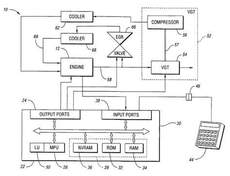
FIGURE 1 is a schematic diagram illustrating operation of a system
or method for EGR./VGT diagnosis and control according to one embodiment of
the
present invention;
2,5 FIGURE 2 is a block diagram illustrating control logic for EGR and
VGT circuits according to one embodiment of the present invention;
FIGURE 3 is a block diagram illustrating operation of a system or
method for VGT diagnostics and control according to one embodiment of the
present
invention; and
-3-
CA 02442970 2003-10-06
WO 02/090751 PCT/US02/05815
FIGURE 4 is a flowchart illustrating operation of a system or method
for EGR diagnostics and control according to one embodiment of the present
invention.
BEST MODE FOR CARRYING OUT THE INVENTION
With reference to Figure 1, an internal combustion engine and
associated control systems and subsystems are generally indicated at 10.
System 10
includes an engine 12 having a plurality of cylinders, each fed by a fuel
injector. In
a preferred embodiment, engine 12 is a compression-ignition internal
combustion
engine, such as a heavy duty diesel engine. The injectors receive pressurized
fuel
from a fuel supply in a known manner. Various sensors are in electrical
communication with a controller 22 via input ports 24. Controller 22
preferably
includes a microprocessor 26 in communication with various computer readable
storage media 28 via data and control bus 30. Computer readable storage media
28
may include airy of a number of known devices which function as read only
memory
32, random access memory 34, and non-volatile random access memory 36.
Computer readable storage media 28 have instructions stored thereon
that are executable by controller 22 to perform methods of controlling the
internal
combustion engine, including variable flow exhaust gas recirculation (EGR)
valve
66 and variable geometry turbocharger 52. The program instructions are
executed
by controller 22 in microprocessor 26 to control the various systems and
subsystems
of the engine and/or vehicle. In addition, various instructions may also be
executed
by any number of logic units 50; Input ports 24 receive signals from various
sensors, and controller 22 generates signals at output ports 38 that are
directed to the
various engine and/or vehicle components.
A data, diagnostics, and programming interface 44 may also be
selectively connected to controller 22 via a plug 46 to exchange various
information
therebetween. Interface 44 may be used to change values within the computer
readable storage media 28, such as configuration settings, calibration
variables,
instructions for EGR and VGT control and others.
In operation, controller 22 receives signals from the various
engine/vehicle sensors and executes control logic embedded in hardware and/or
-4-
CA 02442970 2003-10-06
WO 02/090751 PCT/US02/05815
software to control the engine. In a preferred embodiment, controller 22 is
the
DDEC controller available from Detroit Diesel Corporation, Detroit, Michigan.
Various other features of this controller are described in detail in a number
of U.S.
patents assigned to Detroit Diesel Corporation. Control logic may be
implemented
in hardware, firmware, software, or combinations thereof. Further, control
logic
may be executed by controller 22, in addition to by any of the various systems
and
subsystems of the vehicle cooperating with controller 22. Further, although in
a
preferred embodiment, controller 22 includes microprocessor 26, any of a
number
of known programming and processing techniques or strategies may be used to
control an engine in accordance with the present invention.
With continuing reference to Figure 1, controller 22 provides
enhanced engine performance by controlling a variable flow exhaust gas
recirculation
valve 66 and a variable geometry turbocharger 52. Variable geometry
turbocharger
52 includes a turbine 54 and a compressor 56 mounted on a common shaft 57. The
pressure of the engine exhaust gasses causes the turbine to spin which in turn
drives
the compressor. The spinning compressor creates turbo boost pressure which
develops increased power during combustion.
A variable geometry or variable nozzle turbocharger has moveable
components in addition to the rotor group. These moveable components can
change
the turbocharger geometry by changing the area or areas in the turbine stage
through
which exhaust gasses from the engine flow, and/or changing the angle at which
the
exhaust gasses enter or leave the turbine. Depending upon the turbocharger
geometry, the turbocharger supplies varying amounts of turbo boost pressure to
the
engine. The variable geometry turbocharger may be electronically controlled to
vary
the amount of turbo boost pressure based on various operating conditions.
In a typical variable geometry turbocharger, the turbine housing is
oversized for an engine, and the air flow is choked down to the desired level.
There
are several designs for the variable geometry turbocharger. In one design, a
variable
inlet nozzle has a cascade of moveable vanes which are pivotable to change the
area
and angle at which the airflow enters the turbine wheel. In another design,
the
turbocharger has a moveable side wall which varies the effective cross-
sectional area
of the turbine housing. It is appreciated that embodiments of the present
invention
are not limited to any particular structure for the variable geometry
turbocharger.
-5-
CA 02442970 2003-10-06
WO 02/090751 PCT/US02/05815
That is, the term VGT or VNT as used herein means any controllable air
pressurizing device including the above examples, and including a modulated
waste
gate valve.
An exhaust gas recirculation system selectively introduces a metered
portion of the exhaust gasses into the intake manifold 69. The EGR system
dilutes
the incoming fuel charge and lowers peak combustion temperatures to reduce the
amount of oxides of nitrogen produced during combustion. The amount of exhaust
gas to be recirculated is controlled by EGR valve 66 and VGT 52. In accordance
with the present invention, the EGR valve is a variable flow valve that is
electronically controlled by controller 22. The geometry of the variable
geometry
turbocharger is also electronically controlled by controller 22. There are
many
possible configurations for a controllable EGR valve and embodiments of the
present
invention are not limited to any particular structure for the EGR valve.
Likewise,
various sensors may be used to monitor and control the EGR circuit including
temperature and differential pressure sensors which allow the controller to
determine
the mass flow rate through the valve. In addition, it is appreciated that
various
different sensor configurations may be utilized in various parts of the
exhaust flow
paths to allow controller 22 to determine the various mass flow rates
throughout the
exhaust system, including flow through the EGR system and flow through the
compressor, etc. depending on the particular application..
In some embodiments, it may ~be desirable to provide a cooler 62 to
cool the charge air coming from compressor 56. Similarly, in some embodiments,
it may be desirable to provide a cooler 6~ to cool the flow through the EGR
system
prior to reintroduction into the intake manifold of engine 12 to further
reduce peak
combustion temperatures and the production of nitrogen oxides..
Embodiments of the present invention include control logic that
processes various inputs representing vaxious engine conditions, and in turn,
provides an EGR command signal and a VGT command signal. The EGR command
signal commands a position for the variable flow EGR valve 66 to control gas
flow
through path 64, while the VGT command signal commands a geometry for VGT 52
to control gas flow through path 60. In a preferred embodiment of the present
-6-
CA 02442970 2003-10-06
WO 02/090751 PCT/US02/05815
invention, the various techniques utilized to determine the EGR and VGT
command
signals are best shown in Figure 2.
In Figure 2, a block diagram 80 illustrates the functions of the control
logic, including instructions, executed by controller 22 to provide enhanced
engine
performance and improved emission control. Embodiments of the present
invention
are particularly useful to improve emissions on heavy-duty diesel engines.
Using
EGR technology to mix a portion of exhaust gas with the intake charge reduces
emissions of oxides of nitrogen (NOX), while minimizing fuel economy impact
and
improving durability, in accordance with the present invention. In a
turbocharged
diesel engine, the back pressure necessary to drive the EGR flow from exhaust
to
intake manifold is provided by the variable geometry turbocharger. The control
of
the EGR flow rate may be achieved by changing the geometry of the VGT (for
example, vane position change), by changing the EGR valve position, and
preferably
via a combination of both. In preferred embodiments, the method of control
employed results in interactions between EGR and VGT systems that are beyond
the
capabilities of existing systems.
There are many aspects of the present invention that may be used
separately or together. In the preferred embodiment, the EGR valve and the VGT
are controlled simultaneously and continuously. Preferred implementations of
the
present invention utilize desired intake manifold composition in terms of
chemical
species (02, N2, COz and H20) as a set point for the EGR/VGT controller. The
actual quantity of these chemical species is preferably calculated from a
simplified
combustion model.
With continuing reference to Figure 2, in the embodiment illustrated,
a driver accelerator pedal position sensor input and an engine speed (rpm)
input are
received at block 82. Block 82 utilizes a look up table to determine an engine
torque
demand. The engine torque demand represents a fuel quantity that rnay be
adjusted
for other aspects of engine control that are not specifically described herein
such as,
for example, cylinder balancing. Further, it is appreciated that Figure 2
illustrates
a preferred implementation and that various aspects of the control strategy
shown are
preferred, but not specifically required. At block 84, a one way, second order
filter
adds some delay to the torque demand. Delay is added to allow the slower, air
flow
aspects of engine control to catch up to the faster responding torque demand
aspects
CA 02442970 2003-10-06
WO 02/090751 PCT/US02/05815
of engine control. At block 86, engine speed and filtered torque demand are
received, and processed along with other engine conditions, resulting in
desired fuel
injection timing, quantity, and rail pressure. These factors control fuel
delivery,
indicated at 88.
At block 90, a desired chemical composition for the engine air intake
is determined. The desired composition is in terms of chemical species (N2,
02,
COZ, and HZO). The fuel per cycle is provided to block 90 from injection
control
block 86, and block 90 provides a fuel limit per cycle to block 86 (for
example, fuel
may be limited in low airflow conditions). At block 92, actual flow values for
the
EGR system and turbocharging system, the air/fuel ratio, and chemical
composition
of the intake gasses are calculated. The calculations are based on a
simplified
combustion model and engine sensor inputs. The desired or set point values in
block
90 are based on interpolation of values contained within five pairs of look up
tables.
The first table (94,98) corresponds to stabilized turbocharger boost pressure
and the
second table (96,100) corresponds to zero turbocharger boost pressure. That
is, the
first table corresponds to maximum air per fuel (per cycle) while the second
table
corresponds to minimum air per fuel. Depending on the current air per fuel as
determined from various measurements, desired values are interpolated between
the
two tables for the particular operating value.
For example, desired carbon dioxide and air values are determined
with an interpolation between tables 94 and 96 with each representing two look
up
tables, one table for COZ and one table for oxygen quantity/cycle. Similarly,
desired
values for timing parameters, quantity, and rail pressure are determined by
interpolation (based on air per fuel) between tables 98 and 100 (block 98 and
block
100 each represent three tables). In accordance with preferred embodiments of
the
present invention, controller 22 adjusts VGT and EGR operation to achieve the
desired values at block 90 (calculated by interpolation) within the respective
minimum/maximum tables (96,100 and 94,98, respectively).
Further at block 90, a desired carbon dioxide quantity 110 is
determined. From block 92, an actual carbon dioxide quantity is estimated. It
is
appreciated that the quantities are preferably represented as mass per cycle.
Summer
114 compares the desired carbon dioxide quantity 110 to the actual carbon
dioxide
quantity 112 to determine the carbon dioxide error signal. EGR valve 122 is
_g_
CA 02442970 2003-10-06
WO 02/090751 PCT/US02/05815
controlled by an EGR command signal based on the error signal. Preferably, a
controller, such as a proportional/integral/derivative controller 116 (or
preferably
with a non linear compensation term, for example, a Smith predictor) adjusts
the
EGR valve position to achieve a desired EGR rate and desired carbon dioxide
quantity. Further, in preferred embodiments, EGR loop gain normalization is
contained within block 120 to improve transient response by reducing the
effects of
rapid changes in torque demand.
After loop gain normalization, limiter 119 restricts the EGR command
signal as needed to prevent excessive exhaust smoke during transient engine
operation, as described in further detail in Figure 3. The resultant EGR
command
signal is supplied by controller 22 (Figure 1) to EGR valve 122. Preferably,
the
EGR command signal is also passed to the VGT control, as described below.
In controlling VGT 174, a base geometry (vane position in the
preferred implementation), is determined at block 160 based on torque demand
and
engine speed. The base geometry block 160 serves as a feedforward feature for
VGT
control to improve transient response and also enable open loop control when
desired
as described further below The commanded base position is passed from block
160
to block 161. At block 162, a brake interface allows engine braking control
logic to
override a commanded base position by the normal VGT logic in the event that
the
engine is being operated as an engine brake.
The EGR command signal is received by lead compensation logic 140
to determine a lead compensated signal based on the EGR command signal. In
embodiments of the present invention, this portion of the control loop
synchronizes
simultaneous EGR valve and VGT geometry control. Particularly, when EGR valve
control alone is not sufficient to achieve desired EGR rate, the VGT geometry
is
modified to increase air flow through the turbine until the desired EGR flow
is
achieved. The lead term 140 improves transient response to compensate for the
turbo boost lag. That is, when EGR valve control and VGT geometry control are
not sufficient to achieve desired carbon dioxide content in the engine intake,
increased flow through the turbine increases the overall air flow, but the
turbine
becomes less efficient, increasing the back pressure that drives carbon
dioxide
containing exhaust gasses through the recirculation path increasing the carbon
dioxide mass per cycle at the intake.
-9-
CA 02442970 2003-10-06
WO 02/090751 PCT/US02/05815
At block 142, an additional compensation term based on EGR valve
position modifies the lead compensator output. As shown, summer 144 receives a
desired air per cycle signal and an actual air per cycle signal to determine
an air
error. Lead compensator 140 and additional compensator 142 anticipate and
exaggerate the air error when it is expected that the EGR valve is opening.
The air
error determined at block 144 andlor the base geometry (for example vane
position)
as determined at block 160 are used tt~ determine the VGT command signal.
Preferably, at block 148, normalization values contained within block
148 linearize the loop gain of PID controller 150, and serve as a variable
switch
between open and closed loop control approaches. That is, at low air flow
conditions
(low engine speed and low torque demand), the normalization factor reduces the
air
error to zero or to a sufficiently low value so as to be effectively
insignificant in
controlling VGT 174. That is, at low air flow conditions, normalization
effectively
eliminates the air error signal leaving the base geometry (the feedforward
term) to
control the VGT in an open loop fashion. On the other hand, once air flow
reaches
a sufficient level, the gain normalization factor jumps from zero to a
sufficiently
great value to control VGT 174 and linearize PID controller 150. As air flow
continues to increase, the normalization factor decreases because at higher
air flows,
PID controller 150 is more effective. The gain normalization term is zero at
low air
flows. Air flow is preferably determined as a function of torque demand and
engine
speed. Once significant air flow exists, the gain normalization term is
significantly
increased to change from effectively pure open loop control of the VGT with
the
feedforward term to closed loop control of the VGT (with the feedforward
term).
As airflow continues to increase, the gain normalization term is reduced.
As shown by summer 152, the base vane position (or other suitable
geometry indicator depending on the implementation) from block 160 provides
the
general control of the VGT command signal, while the signal derived from the
air
error provides fine tuning (except at low air flow conditions where the air
error
portion is effectively ignored and open loop control used). Limiter 170 limits
the
VGT command signal as needed to prevent turbo overspeeding. For example, at
higher altitudes, continued demands for more oxygen may result in a turbo
overspeed. This situation is prevented by turbo speed limit at block 172.
After
limiting, if necessary, the VGT command signal is applied to VGT 174. As
-10-
CA 02442970 2003-10-06
WO 02/090751 PCT/US02/05815
explained above, the EGR command signal is utilized (with lead compensation)
to
adjust an air error signal to provide fine tuning of the VGT command signal.
As
such, continuous, simultaneous control of both the EGR and VGT systems allow
the
effects of these systems on each other to be taken into account during the
control
strategy. Lead term 140 improves transient response. Accordingly, the control
loop
also works in the opposite direction, adjusting the EGR valve position if a
desired
boost (or air/fuel ratio) is not achieved. For tables 94 and 96, at lower
oxygen per
fuel, the value in the minimum COZ table commands a desired carbon dioxide
quantity of zero. The upper COZ table is desired C02 quantity at an upper
oxygen
per fuel ratio. The lower C02 defines a lower oxygen per fuel ratio at which
desired
C02 is zero. That is, when the engine is already running fuel rich, tables 94
and 96
are interpolated such that the desired carbon dioxide quantity is zero. As
such, the
function used to interpolate between the two carbon dioxide tables may be
significantly different than the function used to interpolate between the two
air
quantity tables. Further, it is appreciated that the interpolation between any
two
tables is not limited to linear interpolation, but may take other forms.
Referring now to Figure 3, a flow chart illustrating a method for
diagnosing engine component failures according to one embodiment of the
present
invention is shown. More specifically, the embodiment illustrated in Figure 3
may
be used to determine whether the VGT circuit is functioning properly and
control the
engine and/or vehicle accordingly.
Block 200 initiates the VGT diagnostic routine. The controller
determines whether the engine is currently operating in a turbo boost control
mode
or EGR control mode as represented by block 202. If the engine is operating in
boost control mode, the controller determines the current boost pressure as
represented by block 206. At block 20~, the engine controller determines
whether
the current boost pressure is equal to a desired boost pressure corresponding
to a
desired base or steady boost +/- a boost response range. If the boost pressure
is not
within the desired boost pressure range and this condition exists for a
predefined
period of time as determined by block 210, then a VGT fault is indicated and a
corresponding fault indicator light is activated as represented at block 212.
If the
current boost pressure is within the desired boost pressure range as
determined by
-11-
CA 02442970 2003-10-06
WO 02/090751 PCT/US02/05815
block 208, or the required time has not elapsed as determined by block 210,
the logic
continues to monitor the conditions as illustrated.
If the engine is in EGR control mode as determined by block 202, a
current EGR mass flow rate is measured by an associated sensor or sensors as
represented by block 220. At block 222, the engine controller determines
whether
the current EGR mass flow rate is equal to a desired EGR mass flow rate
corresponding to a base rate +/- a minimum flow response. If the EGR mass flow
rate is not within a desired mass flow rate range as determined by block 222,
and
this condition exists for a predefined period of time as determined by block
224, then
an EGR fault indicator is activated as represented by block 226. Further, if
this
condition persists for a second predefined period of time as represented by
block
228, the engine operating mode reverts back to boost control mode and the EGR
valve is commanded to a closed position.
Figure 4 illustrates one embodiment for an EGR diagnostic routine
according to the present invention. The EGR diagnostic routine is initiated as
represented by block 298. A current EGR mass flow rate is sensed, as
represented
by block 300. At block 302, the operating mode is identified as being boost
control
mode or EGR control mode. When operating in boost control mode, block 304
determines whether the EGR mass flow rate exceeds a maximum EGR flow for boost
mode. If the maximum boost mode EGR flow rate is exceeded for a calibratable
period of time as represented by block 306, a corresponding fault code is
activated
which preferably illuminates the check engine light to alert the operator.
As also illustrated in Figure 4, if the engine is operating in EGR
control mode as determined by block 302, the EGR mass flow rate as determined
by
a corresponding sensor or sensors is compared to a corresponding minimum flow
rate threshold at block 310. If the EGR mass flow rate is less than the
corresponding
minimum threshold for a predetermined period of time as determined by block
312,
a corresponding fault is activated as represented by block 314. If this
condition
persists for another predetermined period of time as represented by block 316,
the
control mode reverts to boost control mode as represented by block 318.
As such, the present invention provides a system and method for
diagnosis and control of interrelated engine components. In particular, the
present
invention provides a method for differentiating between VGT and EGR related
faults
-12-
CA 02442970 2003-10-06
WO 02/090751 PCT/US02/05815
and activating an appropriate fault code and modifying the engine control
accordingly. More accurate fault codes may reduce the time necessary for
service
and maintenance personnel to troubleshoot and correct the root cause of any
problem. In addition, engine control may be adjusted based on the fault to
ameliorate the effects of a degraded or failed component.
While embodiments of the invention have been illustrated and
described, it is not intended that these embodiments illustrate and describe
all
possible forms of the invention. Rather, the words used in the specification
are
words of description rather than limitation, and it is understood that various
changes
may be made without departing from the spirit and scope of the invention.
-13-