Note: Descriptions are shown in the official language in which they were submitted.
CA 02443044 2004-08-18
METHOD OF HUMIDIFICATION AND APPARATUS
FIELD OF THE INVENTION
The invention relates to methods of humidification such as methods of
humidifying a
sterilization chamber in a sterilization process using humidified ozone as the
sterilant or
sterilizing agent.
BACKGROUND OF THE INVENTION
Sterilization is the destruction of any virus, bacteria, fungus or othermicro-
organism, whether
in a vegetative or in a dormant spore state. Conventional sterilization
processes for medical
instruments have involved high temperatures (such as steam and dry heat units)
or toxic
chemicals (such as ethylene oxide gas, EtO). Steam sterilization with an
autoclave has been
the time-honoured method of sterilization. It is fast and cost effective.
However, the autoclave
destroys heat-sensitive instruments. Thus, since more and more heat-sensitive
instruments
such as arthroscopes and endoscopes are used in medical treatment, othertypes
of sterilization
are needed, especially cold sterilization.
Ethylene oxide may be used to cold sterilize heat-sensitive instruments.
However, It has now
been deemed by national health and safety organizations to be carcinogenic and
neurotoxic.
It also poses flammability problems and is thus usually used in combination
with
chlorofluorocarbons (CFC's) which themselves are now undesirable. Further,
sterilization
with ethylene oxide takes 14 to 36 hours.
A more efficient, safer, and less expensive sterilization agent is ozone (03).
Ozone, especially
humidified ozone, is a sterilizing gas. Ozone can easily be generated from
oxygen, especially
hospital grade oxygen. Oxygen is readily available in the hospital
environment, usually from
a wall or ceiling oxygen source, or, if mobility is required, from a portable
"J" cylinder of
oxygen. Ozone is widely used in industry as an oxidising agent to bleach paper
pulp, treat
drinking water, and sterilize sewage water and food products. The amounts
(concentrations)
-1-
CA 02443044 2004-08-18
of ozone required in the sterilization gas for water purification are low,
generally less than 40
mg /I (milligram per litre). However, higher concentrations, combined with
critical humidity
levels, are required to make ozone an effective sterilant of micro-organisms.
Those high
concentrations of ozone gas have to be combined with critical levels of
humidity. The
sterilization efficiency of ozone increases rapidly with increased relative
humidity. A high
relative humidity is required for ozone to penetrate the protective shells of
micro-organisms.
The presence of water vapour will also accelerate ozone reactions with organic
substances.
Sufficient relative humidity further helps the penetration of sterilization
packaging by ozone.
Sterilization with ozone is more efficient and quicker than with EtO and
requires few changes
in user habits. Moreover, ozone-based processes are compatible for use with
current
packaging, such as sterile pouches and rigid containers.
Ozone sterilization requires substantially no aeration or cooling down of
sterilized instruments
which can be used immediately following sterilization. This allows hospitals
to reduce the
cost of maintaining expensive medical device inventories. Ozone sterilization
offers several
other advantages. It produces no toxic waste, does not require the handling of
dangerous gas
cylinders, and poses no threat to the environment or the user's health.
Stainless-steel
instruments and heat-sensitive instruments can be treated simultaneously,
which for some
users will obviate the need for two separate sterilizers.
U.S. Patent No. 3,719,017 discloses the use of a mixture of ozone gas with a
very fine water
mist in a sealed plastic bag container which contains an article to be
sterilized. The method
involves repeated evacuation and refilling of the plastic bag with a mixture
of ozone gas and
a very fine water mist. The air in the bag is exhausted and replaced with a
pressurised mixture
of ozone and water mist. Upon encountering the much lower pressure within the
bag, the
water particles from the pressurised mixture explode, forming a water mist.
However, this
system cannot generate a sufficiently high water vapour concentration to
provide the high
relative humidity required for thorough sterilization (at least 85% relative
humidity).
-2-
CA 02443044 2010-11-08
U. S. Patent No. 5,069,880 describes a device capable of generating a relative
humidity of
85%. In the apparatus the ozone is bubbled through a water bath to increase
the water content
of the gas. Although ozone at 85% humidity can kill most micro-organisms, it
does not meet
the "worst case scenario" stipulated in North American standards. Moreover,
the device is
unable to generate humidity levels higher than 85%. In addition, injecting
ozone while
humidifying the chamber increases the contact time of the ozone with the
instruments to be
sterilized, which may result in oxidation damage to the instruments.
A minimum relative humidity level of 90% (95% 5%) is required to meet North
American
standards set by agencies such as the Food and Drug Administration and Health
Canada.
Water evaporates at 100 C at atmospheric pressure (1013 mbar or 760 Torr).
Thus, various
prior patents (see Faddis et al., U.S. Patents No. 5,266,275; 5,334,355; and
5,334,622) teach
sterilization systems wherein water is heated to above the boiling point to
evaporate the water
for injection into the ozone-containing gas produced by an ozone generator.
The steam is
heated to 120 C. Thus, the vapour upon injection into the ozone-containing gas
will have a
temperature close to 100 C. However, since the decomposition of ozone
increases
exponentially with temperature in the range of 20 to 300 C, injecting the
water vapour at a
temperature of about 120 C leads to premature ozone decomposition. As a
result, the
effective ozone concentration in the gas produced by the ozone generator is
reduced, thereby
requiring significantly increased treatment times and the generation of larger
amounts of
ozone gas for each sterilization cycle. Thus, a more efficient and effective
sterilization
apparatus is desired for the sterilization of ozone at a relative humidity of
above at least 90%.
U.S. Patent No. 7,128,872 addresses these problems by applying a vacuum
pressure to
lower the boiling point of water
-3-
CA 02443044 2004-08-18
below the temperature inside the sterilization chamber. Thus the teachings of
this application
provide an effective sterilization process.
As taught in this prior application, it is preferred to repeat the
sterilization cycle at least once
to give greater assurance of effective sterilization. Thus, after loading the
sterilization
chamber with the articles to be sterilized (such as medical instruments), a
sterilization cycle
includes exposing the articles to the humidified ozone sterilant and then
removing the
sterilant. Repeating this cycle thus includes exposing the articles again to
humidified ozone
sterilant and removing the sterilant.
However, as mentioned above, in order to be sure of sterilization using ozone,
the humidity
should be at least 90% (95% 5%). Consistently achieving such high humidity
levels has
proved difficult. The sterilization chamber is in communication with a source
ofwatervapour,
for example, a water reservoir. As taught in US Patent Application Serial No.
10/005,786
mentioned above, a reduction in pressure will cause water in the reservoir to
evaporate.
However, this evaporation leads to cooling of the reservoir. Also,
condensation of water
vapour in the chamber tends to heat the chamber.
Any increase in the chamber temperature increases the quantity of water vapour
required to
reach the target humidity. Attempts to speed the process involve large thermal
energy inputs,
for example excessive heating of the water reservoir. This thermal energy
eventually reaches
the chamber and results in a temperature increase in the chamber which
increases the quantity
of water vapour needed for a given relative humidity. Thus achieving a high
relative humidity
with the consistency and accuracy needed to ensure complete sterilization is
challenging.
SUMMARY OF THE INVENTION
It has now been found that effecting the humidification in a plurality of
graduated steps or
stages can provide a consistent and accurate way to reach a particular value
of relative
-4-
CA 02443044 2010-11-08
humidity, especially high relative humidity values such as those required for
ozone
sterilization.
According to one aspect of the present invention there is provided in a
process for
increasing a relative humidity in an enclosed space from a first relative
humidity to a
target relative humidity by increasing the relative humidity in a plurality of
graduated
steps.
According to another aspect of the present invention there is provided a
method for
humidifying an atmosphere in a sterilization chamber to a target relative
humidity, the
method comprising the steps of a) providing an amount of water in a water
reservoir at a
reservoir temperature TS at or above a temperature of the chamber atmosphere
Tc; b)
reducing a pressure in the chamber to a value below the boiling point of water
at the
reservoir temperature T, c) bringing the reservoir into fluid communication
with the
chamber via a conduit for exposing the water in the reservoir at the
temperature TS to the
reduced pressure in the chamber for a preselected exposure time so that water
in the
reservoir is boiled and to allow resulting water vapour to enter the chamber
and
disconnecting said fluid communication after said preselected exposure time;
and
repeating at least steps b) and c) a plurality of times, wherein at least one
of the amount of
water and the exposure time are controlled such that the relative humidity in
the chamber
progressively increases with each repetition until the target humidity is
reached and
wherein after each step c) the conduit is closed for a time sufficient to heat
the water in the
reservoir and to adjust the reservoir temperature TS so that the reservoir
temperature TS is
equal to or above the temperature Tc of the chamber atmosphere, and a
temperature
differential AT during each step c) is controlled to maintain the temperature
Tc of the
chamber atmosphere substantially constant, wherein AT is defined by the
formula AT =Ts
_Tc.
According to another aspect of the present invention there is provided a
method of
humidifying an enclosed space to a target relative humidity, the method
comprising a
plurality of humidification stages S" ... S , wherein x is an integer from 1
to n and each x
represents an individual stage, each said stage having a corresponding water
vapour
pressure h,, ... hn, and hõ representing the water vapour pressure
corresponding to the
target relative humidity, each said stage Sx including the steps of. a)
supplying water
vapour from a water vapour source to the enclosed space to increase the water
vapour
-5-
CA 02443044 2010-11-08
pressure in the enclosed space to at least the value hx corresponding to said
stage SX; b)
disconnecting the source from the enclosed space for a preselected
equilisation period; and
c) repeating steps a) and b) until said water vapour pressure hõ is reached in
the space,
wherein the water vapour source is a water reservoir, the temperature of the
water vapour
source is T, the temperature of the enclosed space is T,, which is represented
by the
equation T,-T,=AT wherein TS is the same as, or higher than, Tc so that
AT,<<O, and step b)
comprises disconnecting the source from the enclosed space for a time
sufficient to adjust
T, or Tc to achieve the value for A T, and controlling the temperature
differential AT to
maintain T, substantially constant.
According to another aspect of the present invention there is provided an
apparatus for
sterilization with humidified ozone, the apparatus comprising a sterilization
chamber, a
reservoir to hold water while in operation, to provide a source of water
vapour to humidify
the ozone, a conduit in fluid communication between the reservoir and the
sterilization
chamber, a valve in the conduit to open and close the conduit, a first heating
means to
control the temperature of the chamber, a second heating means to control the
temperature
of the reservoir, a first temperature sensing means to monitor the temperature
of the
sterilization chamber, a second temperature sensing means to monitor the
temperature of
the reservoir, a pressure sensing means to monitor the pressure in the
chamber, vacuum
means to reduce the pressure in the chamber, a processor to control the first
and second
heating means in response to information from the first and second temperature
sensing
means and the pressure sensing means, wherein the processor is programmed to
effect a
humidification of the sterilization chamber in a plurality of stages and to
control a
temperature difference between the first and second heating means to maintain
the
temperature of the chamber substantially constant.
The invention will be described with reference to an ozone sterilization
process using
humidified ozone. However it will be understood that the humidification
process
according to the invention is applicable to any process which requires
accurate
humidification.
In a sterilization process, the space to be humidified would be the
sterilization chamber.
In the preferred use of the stage-wise humidification in a humidified ozone
sterilization
process, the process would normally additionally include other steps such as
placing a load
of instruments to be sterilized into a sterilization chamber and injecting
ozone into the
chamber.
-6-
CA 02443044 2004-08-18
Throughout this description, units of pressure will be variously indicated in
mbar, Torr,
atmospheres or 1/4 Torr. I atmosphere equals 760 Toff or 1013 mbar.
One or more ventilating cycles can be added to the preferred method for
removing the
remaining ozone and humidity from the sterilization chamber.
BRIEF DESCRIPTION OF THE DRAWINGS
The invention will be described in more detail in the following by way of
example only and
with reference to the attached drawings wherein
FIG. 1 is a flow diagram of a method in accordance with the invention;
FIG. 2 is a graph to illustrate the sequence of steps in a method in
accordance with the
invention by plotting pressure against time;
FIG. 3 is a schematic illustration of an apparatus suitable for use with the
method of
invention; and
FIG. 4 is a graph showing progress of a humidification step according to the
invention.
DETAILED DESCRIPTION OF THE PREFERRED EMBODIMENT
Preferably the source of water vapour is a reservoir of water in a humidifier
chamber or
humidifier unit. The temperature of the water vapour source or the water in
the reservoir may
be represented as T. The temperature of the space to be humidified or the
sterilization
chamber may be represented by T. Preferably there is at least one heating
means for each of
the sterilization chamber and the reservoir. Such heating means may be
referred to as a first
and second heating means. Preferably the reservoir water is at the same
temperature as or a
higher temperature than the temperature of the sterilization chamber, that is,
TS >_ T. The
difference in temperatures may be expressed as AT (delta T) so that T, - T, =
AT and thus AT
0. Preferably the temperature difference AT is from 0 to 10 C, more preferably
from 0 to
7 'C and particularly from 0 to 3 C. Maintaining the reservoir water at a
higher temperature
encourages evaporation ofwater vapour and encourages the vapour to flow to the
sterilization
-7-
CA 02443044 2003-09-26
chamber and discourages loss of humidity from the sterilization chamber by
recondensation
in the reservoir.
The number of stages to be used to complete the humidification, or to achieve
the target
relative humidity, is widely variable. A large number of stages could be used.
Selection of the
number of stages will depend on the accuracy of the equipment used and a
preference to
complete the humidification as quickly as possible without adversely affecting
the ability to
accurately obtain the desired relative humidity. Thus, out of convenience,
humidification
would preferably be achieved in less than 50 stages, more preferably from 3 to
30, or from 5
to 27.
In a presently preferred embodiment, a processor is programmed with
information
corresponding to 27 stages (shown hereafter in Table 1) although the last 10
to 15 stages are
included in case the sterilization chamber temperature T, increases beyond the
preferred
temperature (thus requiring a higher water vapour pressure to achieve the same
value of
relative humidity) but they are not always required. Similarly, depending on
the
circumstances, it is sometimes possible to achieve up to 60%, or even up to
80% of the target
Relative Humidity in a first stage, so that in the 27 stages (shown hereafter
in Table 1), the
first few stages, preferably up to 5 stages (which in a preferred embodiment
would correspond
toa water vapour pressure of 112 x 1/4 Torr) may be combined into a first
single stage. It is
preferred to reach a water vapour pressure of about 80 x 1/4 Torr in a first
stage.
If it is attempted to proceed too quickly or in too few stages, condensation
will tend to occur
in the sterilization chamber which will increase the chamber temperature which
will in turn
impose a need for a greater amount ofwater vapour to reach the target relative
humidity. Such
an unfavourable sequence can become out of control so that the target relative
humidity
cannot be reached. Thus it is preferred to take at least 5 to 10 stages,
preferably 10 or more,
to reach the target relative humidity.
-8-
CA 02443044 2003-09-26
Even more care should be taken in the later stages to allow the system to
stabilize. Thus it is
preferred that at least the last 10 stages, preferably the last 5 stages,
particularly the last 3
stages should be effected in such a way that the increase in water vapour
pressure achieved
in the sterilization chamber is in a small increment for each stage, for
example from 0.1 to 5
Torr, preferably 0.1 to 3 Torr and particularly from 0.25 to I Torr. In a
preferred embodiment
the last 10 or more stages are pressure increments of about 0.5 to 1 Torr.
The humidification thus should proceed in graduated stages, preferably in
fairly discrete
stages. Thus in a given stage, after reducing the pressure in the water
reservoir (for example,
by evacuating the sterilization chamber and opening a valve to put the
reservoir and
sterilization chamber in fluid communication) the boiling point of the water
in the reservoir
will be reduced below the actual temperature of the water, thus the water will
boil, water
vapour will be formed and can thus travel or flow to the sterilization
chamber. The
evaporation will cause the temperature of the water reservoir to drop. It is
thus necessary to
heat the reservoir to return the temperature T, back to or above the chamber
temperature Tc.
During this re-heating, it is preferred to close the valve in the conduit
joining the chamber to
the reservoir. Thus the reheating becomes a preparation for the next stage.
Thus the valve is
closed, disconnecting the reservoir or water vapour source from the chamber
for a time
sufficient to adjust either the chamber temperature, or preferably the
reservoir temperature,
to return T, to the preferred value of T, or above.
In order to better control the stages, it is preferred that there is a
temperature sensing means
to monitor the temperature of the water in the reservoir. A temperature
sensing means is also
preferred to monitor the chamber temperature. Thus if the chamber temperature
sensing means
is referred to as a first temperature sensing means, then the reservoir
temperature sensing
means may be referred to as a second temperature sensing means or temperature
sensing
device. A suitable device is aResistance Temperature Dependent sensor (RTD)
such as a class
B type sensor commercially available from Omega Temperature. This type of
device has a
resolution of 100 degrees, a standard deviation of 0.00385 and a tolerance of
0.3 degrees
-9-
CA 02443044 2003-09-26
which means that it can measure a temperature to an accuracy of within about
0.15 degrees.
The temperature sensing means are preferably connected to a processor,
computer or
programmable logic controller so that the temperature data can be fed to the
processor. The
RTD provides temperature measurements to a processor which can adjust the
heating
accordingly, by means of a Proportional Integral Differential (PID) function
of the
Programmable Logic Controller (PLC). The heating means are connected so as to
be under
control of the processor. Thus by also providing pressure sensing means to
monitor the
pressure in the chamber, and connecting this also to the processor, the
humidification stages
can be automated. The processor may be programmed with a table of target
values of
temperatures, pressures and times, and instructed to proceed with the
humidification
according to a pre-programmed sequence in accordance with the table.
As mentioned above, condensation in the chamber will tend to increase the
chamber
temperature and will run the risk of losing control of the humidification.
Therefore, the
number of stages and the corresponding water vapour pressure values are
selected to reduce
the risk of condensation of water vapour in the sterilization chamber,
preferably to avoid
substantially any condensation in the chamber.
In the preferred use of the stage-wise humidification in a humidified ozone
sterilization
process, the process would normally additionally include other steps such as
placing a load
of instruments to be sterilized into a sterilization chamber and injecting
ozone into the
chamber.
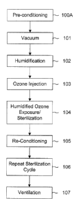
As can be seen from Figures 1 and 2, the process can be regarded as including
six or seven
basic steps, some of which may be repeated in a second sterilization cycle.
Figure 1 is a schematic representation of a sterilization process according to
the invention,
showing the steps of the process in sequence. Figure 2 is another
representation of a process
according to the invention. Figure 2 illustrates the process by showing the
various steps as a
-10-
CA 02443044 2004-08-18
function of the pressure. Thus the vertical axis shows the pressure, with
atmospheric pressure
represented at the top end of the vertical axis and zero pressure (or complete
vacuum) at the
bottom end of the vertical axis. The horizontal axis represents the sequence
of steps in the
process from left to right and thus corresponds to elapsed time, although not
necessarily to
any scale, but only for the purpose of illustration.
Since the present invention is mainly concerned with the humidification step,
it will be
understood that details of other process steps are in the nature of preferred
features which are
not essential to the broadest aspects of the invention.
As shown in Figures 1 and 2, preferably the sterilization is preceded by a
conditioning step,
indicated as step 100A. This step may also be referred to as a pre-
conditioning step. In this
step, after inserting the articles to be sterilized in a sterilization
chamber, the chamber is
sealed.
Generally, it is preferred to effect the sterilization at a target temperature
in the range of from
about 25 to 40'C, more preferably from about 30 to 36'C and especially at
around 30'C, for
example at 30.8 C. The walls of the chamber are preferably maintained at
around this
sterilization temperature. Since this is above usual room temperature, it is
preferred to
successively fill and empty the chamber, with ambient air, in a succession of
pulses. This
pulsing helps stabilize the conditions in the chamber and helps bring any load
(instruments
to be sterilized) to the preferred chamber temperature. This is represented by
the peaks and
troughs shown in Figure 2 in the left-hand portion of the graph indicated as
100A, which
represents the pre-conditioning step. The peaks represent a pressure of around
atmospheric
pressure and thus represent at least partially filling the chamber with
ambient air. The troughs
represent reducedpressure or evacuations of the chamber. Room temperature is
usually around
18 to 22 C so to reach a target temperature of, for example, 30 C, the air
must be heated. The walls
of the sterilization chamber are preferably heated. Thus by pulsing a quantity
of air into and out of the
chamber, the temperature of the air and the temperature of the load (any
instruments in the
-11-
CA 02443044 2004-08-18
chamber for sterilization), approaches the target chamber temperature of
around 30"C.
Generally it is preferred that a reduced pressure in the range of from about
350 to about 450
Torr, more preferably about 250 Torr, is used to evacuate the chamber in each
of the
evacuation pulses in this pre-conditioning step. It is preferred that the
ambient air load is
pulsed from 7 to 16 times, more preferably ten times. However, the number of
such pulses
may be increased or decreased to bring the load of ambient air to a
satisfactory temperature.
Any inert gas may be used as the gas in the pre-conditioning step. The choice
of gas will be
governed by costs or by consideration of whether it will interfere with the
sterilant in the
subsequent sterilization steps. In later steps, it is preferred to avoid using
air since the nitrogen
which it contains may form harmful substances, such as nitrogen oxides as a
result of the
powerful oxidizing capacity of ozone. Such nitrogen oxides may then form
traces of nitric
acids with any water vapour and may thus damage parts, such as metal parts, of
articles to be
sterilized. However, in this pre-conditioning step, air can be used, although
oxygen would be
preferred.
The next step is the vacuum step and is indicated as 101 in Figures 1 and 2.
In this step,
gaseous contents of the sterilization chamber are evacuated. It is preferred
to use a deep
vacuum, generally in the range of from about 5 to 0.5 Torr, more preferably
about 2.5 to 0.5
Torr, more particularly, less than 1.25 Torr to remove as much of the gaseous
contents as
possible. It is preferred to apply this pressure for atime in the range of
from about 30 seconds
to 5 minutes, more preferably about a minute to allow the pressure to
stabilize within the
chamber, especially considering that the articles to be sterilized may well
include containers
and pouches.
The next step is the humidification step and is indicated as 102 in Figures 1
and 2. This step
is to provide the sterilization chamber with the humidity required for
sterilization. Water from
a water reservoir is evaporated and introduced into the chamber as water
vapour until the
relative humidity is equal to or above the target value. It is preferred that
the relative humidity
during sterilization is at least above 90%, preferably 95% or higher. It is
preferred that after
-12-
CA 02443044 2003-09-26
the target humidity is reached, conditions are maintained to stabilize and
equilibrate the
conditions throughout the chamber and the articles in the chamber. Preferably
conditions are
maintained for a time in the range of from about 10 to 50 minutes, more
preferably for at least
30 minutes.
Relative humidity is a percentage and represents the water vapour present as a
percentage of
the theoretical maximum water vapour possible at a given temperature. Thus a
relative
humidity of 100% represents the theoretical maximum water vapour pressure at a
given
temperature. Since warm air holds more water than cool air, an increase in
temperature
requires an increase in water vapour to maintain 100% relative humidification.
The humidification step or humidification phase is a complex process achieved
by graduated
steps or increments.
The means of humidification, or humidifier, includes a source of water,
preferably contained
as a reservoir, to provide the water vapour for humidification. In one
embodiment the, source
of water is provided by a cylinder in which there is a known volume of water
(in a process
using a 125 liter sterilization chamber, a volume of 500 mls or less is
preferred, in particular,
a volume of about 300 mls 10 mis) which is sufficient to provide the
required relative
humidity under the process conditions.
The water in the water reservoir is preferably heated to a temperature which
is equal to or
above the temperature of the sterilization chamber. If the temperature of the
water reservoir
is less than the chamber, then as the humidification progresses, a point will
be reached where
no more water will evaporate from the reservoir even though the target
relative humidity has
not been reached. A lower temperature in the reservoir will thus function as a
"cold spot"
which encourages condensation rather than evaporation.
The water reservoir or source, is in fluid communication with the sterilizing
chamber by
-13-
CA 02443044 2003-09-26
means of a conduit which may be referred to as a water vapour diffuser. The
conduit
preferably includes a valve by which fluid communication between the chamber
and the
source can be disconnected in an "off' position or re-connected in an "on"
position.
Preferably, this conduit, or water vapour diffuser, is also kept at a
temperature above the
temperature of the chamber. The temperature of the water vapour diffuser is
also preferably
monitored, by a sens or such as an RTD sensor described above, and the
measured temperature
information sent to a processor so that appropriate heating adjustments may be
made to
maintain a desired temperature. Preferably, the water vapour diffuser is
maintained at about
3 C ( 0.5 C) above the temperature of the water source.
Since the water source is also usually kept above the temperature of the
chamber during the
humidification step, this means that the water vapour diffuser may often be
some 7 or 8 C
higher that the chamber.
Before starting the humidification stage, the water source is heated to a
temperature
corresponding to the average temperature of the sterilization chamber. As
mentioned above,
a preferred sterilization chamber temperature is around 30.8 C.
Just before the HS (humidification step) a vacuum is applied to the
sterilization chamber to
reduce the pressure in the chamber, preferably to about 5/4 Torr. At this
pressure, the boiling
point of water is -15 C. Thus, if the water source or reservoir is at or above
the preferred
chamber temperature of 30.8 C, when the valve in the water vapour diffuser is
opened, the
water source will be in fluid communication with the sterilization chamber and
water will
evaporate from the reservoir and enter the sterilization chamber.
As mentioned above, in order to consistently and precisely obtain a particular
relative
humidification valve, especially the high values of 90% or higher, which are
preferred (and
sometimes required) for efficient ozone sterilization, there are many
difficulties to overcome.
-14-
CA 02443044 2003-09-26
When the water reservoir, which is at a temperature of, for example, 30.8 C is
exposed to the
low pressure of the chamber at for example, 5/4 Torr, by means of opening the
valve, water
will immediately evaporate and the resulting water vapour will enter the
sterilization chamber.
However, the evaporation has a cooling effect which will also lower the
temperature of the
water source.
In practice, at the start of the humidification step, when the valve is
opened, although water
vapour enters the sterilization chamber, the quantity ofwater vapour which
enters the chamber
is insufficient to produce a high relative humidity especially the relative
humidity values at
or above 90% which are required for ozone sterilization. Further, in practice,
the Sterilization
chamber has "cold spots". These are locations within the chamber which are at
a lower
temperature than the average chamber temperature or lower that the target
temperature. Such
"cold spots" may be provided by components of the load (the medical
instruments to be
sterilized) within the Sterilization chamber which may not have reached the
target
temperature, or they may be provided by structural limitations of the chamber
itself (such as
supporting members to support the configuration of the chamber which members
cannot be
directly heated, but only heated indirectly from the other chamber
components). Such "cold
spots" may induce some condensation. Any condensation in the chamber will
tendto increase
the temperature of the chamber (because of the thermal energy emitted by the
condensation
process). Any increase in chamber temperature will increase the water vapour
needed to reach
the desired relative humidification. Further, in some systems, the chamber may
not be
provided with any cooling means and thus quickly reducing the temperature to
the preferred
target temperature value, may not be possible. Further, simply continuing to
heat the water
source to obtain the desired water vapour content will tend to exacerbate any
problems such
as those caused by condensation on "cold spots".
According to the invention the humidification preferably proceeds in a number
of graduated
steps which may be indicated as a series S1, S2, S3 ... Sõ in which n
indicates the number of
steps. Thus an intermediate step in this series may be represented as S,; in
which x is the
-15-
CA 02443044 2003-09-26
number of the step between 1 and n. For each of the steps there is a
corresponding water
vapour pressure h, h2 ,,,h,,, which represents a target water vapour pressure
value for the
corresponding stage. Thus an intermediate step S,; would have a corresponding
water vapour
pressure value hX.
If both the temperature of the chamber and the water vapour pressure in the
chamber are
known, then the relative humidity may be calculated. At a temperature of 30.8
C, for 100%
relative humidity, the water vapour pressure is 34 Torr.
As mentioned above, it is preferred that the temperature of the water source
is kept above the
chamber temperature. This temperature differential (being the difference in
temperature
between the water source and the Sterilization chamber) may be represented as
AT (delta T).
Further, it is preferred that the temperature differential is selected
according to each individual
humidification stage. Thus, for example, the temperature differential may be
chosen to be
higher in the earlier stages and less in the later stages or vice versa. In
practice, a series of
suitable temperature differentials dtl, dt2, ...dtõ each corresponding to the
humidification stage
of the same number, is selected for optimum control of the humidification. An
intermediate
stage S,, will thus have an associated AT value of AT,. Towards the latter
stages of the
humidification, the temperature difference will preferably level out to avoid
overheating the
water and causing the chamber temperature to increase undesirably.
A preferred humidification step may have many individual stages. The following
Table 1
shows 27 possible stages with corresponding pressure and temperature
differential values.
-16-
CA 02443044 2003-09-26
Table 1: Correspondence table between humidification stage,
water vapor pressure set point, and Delta T applied to the humidifier
temperature
set point
Humidification stage Water vapor pressure Set Delta T (1/100 C)
point (1/4 Torr)
1 0 0
2 80 75
3 100 125
4 108 175
112 225
6 116 275
7 120 325
8 122 375
9 124 433
126 485
11 128 533
12 130 570
13 134 585
14 138 600
142 600
16 146 600
17 150 600
18 154 600
19 158 600
162 600
21 166 600
22 170 600
23 174 600
24 178 600
182 600
26 186 600
27 190 600
In Table 1 above, the left hand column gives the number of the individual
humidification
stage, the middle column gives the associated water vapour pressure for that
stage (in the
table, the pressure is given in units of 1/4 Torr) and the right hand column
indicates the
-17-
CA 02443044 2003-09-26
preferred temperature differential for that particular humidification stage,
that is, the
difference in temperature between the chamber and the water source (the
temperatures in table
1 are given in units of hundredths of a degree centigrade).
This table of values is programmed into a processor (such as a computer, for
example the
PLC), so that the parameters can be controlled automatically in response to
the particular
conditions, such as chamber temperature and pressure, as measured by the
system
components.
Looking at Table 1 in more detail, at the start of the humidification step the
water source is
at approximately the same temperature as the chamber and the chamber has just
been
evacuated (at least preferably to a pressure of 5/4 Torr). This represents
stage 1 with
corresponding water vapour pressure of 0 and temperature differential (Delta
T) of 0. The
valve is then opened and water evaporates from the source to enter the
sterilization chamber
as water vapour. The valve is shut and the water source is heated to 75/100 C
above the
chamber temperature. The valve is now opened again. This is now stage 2 of the
humidification, and when the pressure in the chamber reaches 80 x 1/4 Torr (as
shown in Table
1 as the pressure corresponding to stage 2) the valve is closed and the water
source is heated
to 125/100 degrees above the chamber temperature and the valve is opened for
stage 3 until
the corresponding pressure of 100 x 1/4 Torr is reached.
The process is repeated through all the stages until the relative humidity in
the chamber is
calculated to be equal or above the target relative humidification.
As mentioned above, for a chamber temperature of 30.8 C, a relative humidity
of 100% is
representedby awater vapour pressure of 34 Torr. However, during the process,
the chamber
temperature may exceed the preferred temperature, and thus a higher water
vapour pressure
will be needed to give the same relative humidity value. The chamber
temperature is regularly'
monitored and the value is provided to the processor. The processor keeps
repeating the
-18-
CA 02443044 2003-09-26
humidification stages from S1 to S2 to S3 etc. until the water vapour pressure
inside the
chamber (for the actual chamber temperature) corresponds to the target
relative humidity.
Table 1, which is programmed into the processor, thus has a sufficient number
of
humidification steps, with corresponding pressure and temperature information,
to ensure that
even when the chamber temperature increases beyond the preferred temperature,
the processor
has sufficient information to ensure reaching the target relative
humidification.
It is also preferred to run the humidification step for a minimum time to
further assist in
ensuring proper humidification.
It is preferred that the target humidity is reached within 10 to 31 minutes.
Thus, when the
water vapour pressure set point is reached (which is 34 Torr + 0.25 Torr for a
chamber
temperature of 30.8 C) a "humidification plateau" is allowed for from 10
minutes to 1 hour,
preferably for at least about 31 minutes. During the humidification plateau,
the water vapour
diffuser is kept at 37 C to avoid any condensation in the diffuser and the
valve is kept open
to allow any additional water vapour which may be needed to maintain the
target relative
humidification (since, in practice, the chamber temperature may increase
during the
humidification plateau).
The minimum humidification time is preferably 50 minutes. If the minimum water
vapour
pressure is reached in less than 19 minutes, the "humidification plateau" is
extended beyond
the preferred 31 minutes to ensure a total humidification time of at least 50
minutes.
Otherwise, if the minimum water vapour pressure takes longer that 19 minutes
to reach, the
"humidification plateau" is still kept for 31 minutes, so the total
humidification step will last
longer than the minimum 50 minutes.
The temperature of the sterilization chamber is monitored regularly. The
temperature may be
measured by using a device such as the RTD sensor discussed above. It is
preferred to
-19-
CA 02443044 2003-09-26
measure the chamber temperature indirectly. Since the mass of the gas in the
chamber is so
small, direct measurement would be inaccurate. The chamber temperature is
therefore
obtained by averaging measurements of the chamber back wall , top wall and
bottom wall.
Thus TA\; [TR + TT+ TB]
3
Where TAV = Average chamber temperature
TR = Temperature of rear wall
TT = Temperature of top wall
and TB = Temperature of bottom wall
The temperature controls are summarized as follows.
While the sterilizer is not in the Humidification phase: the water vapor
diffuser temperature
setpointis 37 C+0,5 C; the Humidifier heater set point is: [Average Chamber
Temperature];
and the chamber door heater setpoint is [Average Chamber Temperature].
During the Humidification phase: the Humidifier heater set point is [Average
Chamber
Temperature] + [Delta T]c xt e; the water vapor diffuser temperature set point
is: [TRTDH,,mj ier]
+ [3 C 0,5 C]; and the chamber door heater setpoint is [Average Chamber
Temperature].
The values for [Delta T] C11,e are values obtained from Table 1.
Thus there is what may be referred to as a thermal inertia. That is, thermal
energy added to
the system, for example the heat which is applied to the water source, takes
time before it is
-20-
CA 02443044 2004-08-18
distributed throughout the whole system, even to the perimeters of the system.
Figure 4 shows the progress of a humidification using graduated steps. The
vertical axis
shows the pressure in the Sterilization chamber in units of 1/4 Torr. The
horizontal axis shows
the time. The target water vapour pressure at the preferred chamber
temperature of 30.8 C
is about 136 x 1/4 Torr (which is 34 Torr). After this pressure has been
reached, the valve is
kept open so that the water source and the chamber are in fluid communication
during the
"humidification plateau". The target water vapour pressure of 136 x 1/4 Torr
is shown on the
figure as the water vapour setpoint. After reaching the setpoint, the
"humidification plateau"
is maintained for 31 minutes as shown in the figure. It can also be seen from
the figure that
in the last 5 to 10 minutes of the humidification plateau, there are virtually
no further
increases in pressure, which shows that the conditions in the chamber have
stabilized.
After the humidification step, the next step is an ozone injection step which
is represented as
step 103 in Figures 1 and 2. Ozone is generated by an ozone generator. It is
preferred to
monitor the ozone produced by the generator to ensure that a sufficient
quantity of ozone will
be introduced to the sterilization chamber. Thus preferably the ozone
generator is activated
before the end of the humidification step so that sufficient ozone is being
generated by the
time it is required at the end of the humidification step. For a sterilization
chamber of about
125 Litres, an ozone generation of between 160 and 200 mg/L at normal
temperature and
pressure (NTP) from the generator is preferred. Preferably, used ozone and
unrequired ozone
is catalytically destroyed (by conversion to oxygen) before expelling it to
the atmosphere to
avoid pollution.
A suitable ozone generator produces ozone from oxygen (preferably extra-dry
medical grade oxygen)
which is submitted to an electrical field produced inside the generator,
suitably at a high frequency
voltage of about 10,000 volts peak to peak. The high voltage permits a corona
discharge in the
generator cells to convert the oxygen to ozone. Ozone is heat sensitive, so it
is preferred to
keep the ozone generator operation at around 2 to 4'C to optimise ozone
production. When
ready, the ozone is introduced into the humidified chamber until the ozone
-21-
CA 02443044 2004-08-18
in the chamber preferably reaches a concentration in the range of about 45 to
100 mg/L NTP,
more preferably about 85 mg/L NTP. Coupled with the high humidity, this
concentration is
considered to be sufficient to achieve sterilization.
The next step is the humidified ozone exposure step which is indicated as step
104 in Figures
1 and 2. This step involves maintaining the level of ozone and humidity
achieved from the
previous steps for a time sufficient to achieve a satisfactory level of
sterilization. A time
period of from 5 minutes to 1 hour may be needed, although 15 minutes is
preferred. This step
completes the first sterilization cycle. In the interest of maximising the
assurance of
sterilization, it is preferred to repeat the sterilization with at least a
second sterilization cycle,
preferably including repeating at least steps 101, 102, 103 and 104.
The next step, is a re-conditioning step which is indicated as step 105 in
Figures 1 and 2. The
purpose of this step is to remove any condensed water. Preferably all, or
substantially all of
the condensed water is removed and preferably all, or substantially all of the
water vapour is
removed in this step. It is preferred that the amount of water removed is from
about 75% to
100% by weight of all the water in the chamber, more preferably from about 80%
to 100%.
Thus this step may be regarded as a flushing or purging step to remove
condensed water. It
is also preferred that the temperature of the chamber is restabilized to the
target temperature,
for example, the preferred temperature of 30.8'C. The gaseous vehicle used for
this purging
or flushing step is preferably a gas which is inert in the context of the
sterilization process. For
example, some gases such as nitrogen and other gases, may form undesirable
oxygenated
products by contact with ozone and thus are preferably avoided. In this step,
since it follows a
previous sterilization cycle which has used ozone, it is preferred to avoid
the use of air because
of the high nitrogen content of air. The preferred gas for this step is
oxygen, especially medical
grade dry oxygen, which would usually be readily available in an environment
in which the
sterilization process of the invention would normally be used, such as a
hospital. The reconditioning
step preferably includes, or is preceded by, a vacuum step to remove humidity
and ozone from the
chamber. Preferably a vacuum in the range of about 20 down to 5 Torr, more
preferably less
-22-
CA 02443044 2004-08-18
than 10 Torr, is applied. Gaseous contents removed from the chamber are passed
to a catalyst
to convert any ozone to oxygen, for environmental reasons. It is preferred to
maintain the low
pressure such as the preferred pressure of 10 Torr for a period of time,
preferably 2 to 3
minutes, to allow gaseous contents within articles in the chamber (especially
articles having
pouches and containers) to equilibrate with the rest of the chamber, to
optimise removal.
Medical grade oxygen is then introduced to the chamber. It is preferred that
this re-
conditioning step include at lease one repetition of the vacuum and oxygen
injection steps to
optimise the removal of all condensation.
The removal of condensed water may be referred to as a post-exposure step
since it follows
at least a first sterilization cycle and thus an exposure to the humidified
ozone sterilant.
However, it may be more appropriate to refer to it as a conditioning or re-
conditioning step
(since in preferred processes it may not be the first conditioning step and is
intended to return
the conditions within the chamber to conditions at least approximating those
at the start of the
sterilization).
When all the sterilization cycles have been completed, a ventilation step is
effected, which is
indicated as 107 in Figures 1 and 2. The purpose of this step is to remove
ozone and water
vapour before the sterilization chamber is opened and the sterilized articles
are removed.
It will be readily understood by a person skilled in the art that the sequence
of some of the
steps may be varied without compromising sterilization. Some steps might be
effected
simultaneously although the successive sequence described above is preferred.
An ozone sterilizer apparatus, suitable for use with the method of the
invention is illustrated
schematically in FIG. 3. Medical quality oxygen is subjected in an ozone-
generating unit
including an ozone generator 22 to an electrical field, which partially
converts the oxygen into
ozone. The ozone is then fed into a humidified sterilization chamber 10 where
it sterilises
medical devices. The ozone is subsequently reconverted into oxygen using an
ozone
-23-
CA 02443044 2004-08-18
converting unit 52. The only residues left at the end of the sterilization
cycle are oxygen and
clean water vapour.
The apparatus includes a heated sterilization chamber 10 which can be sealed
to contain a
vacuum. This is achieved with an access door 12, which can be selectively
opened for access
into the chamber and which seals the chamber in the closed condition. The
apparatus further
includes an ozone generator 22 for supplying ozone-containing gas to the
sterilization
chamber, ahumidifier arrangement 30 for supplying water vapour to the
sterilization chamber,
and a vacuum pump 40 (a suitable pump is a dry scroll vacuum pump manufactured
by
Anestiwata). The vacuum pump 40 is used for the application of a sufficient
vacuum to the
sterilization chamber 10 to increase the penetration of the sterilizing gas
and to be able to boil
water at a temperature below the temperature inside the sterilization chamber.
The vacuum
pump 40 in the preferred embodiment is capable of producing a sufficient
vacuum in the
sterilization chamber to lower the boiling point of water in the chamber below
the temperature
in the chamber. In the preferred apparatus, the vacuum pump is capable of
producing a
vacuum of 0.1 mbar. Ozone produced in the ozone-generating unit 22 is
destroyed in an ozone
converting unit 52 to which ozone-containing gas is fed either after passage
through the
sterilization chamber 10 or directly from the ozone-generating unit 22 through
valve 29b. The
ozone piping circuit includes an ozone converting catalyst (such as DEST 25,
manufacturer
TSO3). The ozone converting unit 52 is connected in series before or after the
vacuum pump
40 to prevent ozone gas escaping to ambient air. The ozone decomposing
material in the
preferred catalyst is carulite. For economic and practical reasons, it is
preferred to use a
catalyst to decompose the ozone exhausted from the sterilization chamber 10.
The catalyst
destroys ozone on contact and converts it into oxygen with a certain amount of
heat being
produced. Catalysts of this type and their manufacture are well known to the
person skilled
in the art of ozone generators and need not be described in detail herein.
Furthermore, other means for destroying the ozone contained in the
sterilization gas will be
readily apparent to a person skilled in the art. For example, the gas can be
heated for a
-24-
CA 02443044 2004-08-18
preselected time to a temperature at which the ozone decomposition is
accelerated, for
example, to 300 C.
The humidifier arrangement 30 includes a humidifier chamber 32 (such as HUM
0.5,
manufacturer TSO3) sealed from ambient air and connected to the sterilization
chamber 10
through a conduit and a vapour intake valve 34. The humidifier chamber 32 is
equipped with
a level control to ensure a sufficiently high water level (not shown). Water
is directly supplied
to the humidifier chamber 32 from a drinking or purified water supply
connection. Water is
supplied to the humidifier chamber 32 by way of a filter 33, a pressure
regulator 35, and input
valve 36. The water vapour produced in the humidifier chamber 32 enters the
sterilization
chamber 10 by way of a vapour intake valve 34.
The ozone-generating unit includes an ozone generator 22 (such as OZ, model
14a,
manufacturer TSO3) of the corona discharge type, which is cooled to decrease
the ozone
decomposition rate, as is well known in the art. To achieve a good lethality
rate in an ozone
sterilization process, the ozone supplied in the sterilization chamber should
be sufficient to
obtain a concentration of 48 to 96 milligrams per litre, preferably 50 to 90
milligrams per litre.
At these concentrations, the ozone generation is associated with a relatively
high energy loss
in the form of heat. Generally, about 95% of the supplied electrical energy is
converted into
heat and only 5% is used to produce ozone. Since heat accelerates the inverse
transformation
of ozone into oxygen, it must be removed as quickly as possible by cooling the
ozone
generator 22. The ozone generator in the apparatus is kept at the relatively
low temperature
of 3 to 6 C by either an indirect cooling system with cooling water
recirculation, or a direct
cooling system with a refrigeration unit for cooling. The cooling system 60 is
preferably kept
at the temperature of 3 to 6'C. In the preferred embodiment, the cooling
system is kept at
4 C so that the ozone-containing gas generated by unit 22 is at the ambient
temperature of
around 20 to 35'C, preferably 30'C. Thus, the ozone-containing gas entering
into the
sterilization chamber for humidification and sterilization is kept at ambient
-25-
CA 02443044 2003-09-26
temperatures of from 20 to 35'C. This means that ozone decomposition is kept
to aminimum
and that the sterilization process is more efficient.
The ozone-generating unit is preferably supplied with medical quality or
medical grade
oxygen. The apparatus can be connected to a wall oxygen outlet common in
hospitals or to
an oxygen cylinder or to any other source capable of supplying the required
quality and flow.
The supply of oxygen to the generator 22 takes place across a filter 23, a
pressure regulator
24, a flow metre 25 and an oxygen shut-off valve 26. The generator is
protected against
oxygen over-pressure by a safety pressure switch 27. The ozone-oxygen mixture
generated
by the generator 22 is directed to the sterilization chamber 10 by a needle
valve 28 and a
mixture supply solenoid valve 29a. The mixture can also be directly supplied
to the ozone
converting unit 52 by way of a bypass solenoid valve 29b. In a preferred
embodiment which
includes a sterilization chamber of 125 liters volume, the pressure regulator
24 preferably
controls the oxygen input at a flow rate of about 1.5 litres per minute.
However, it will be
readily apparent to the skilledperson that other flow rates may be used
depending on the make
and model of the ozone generator 22 and the size of the sterilization chamber.
The apparatus in accordance with the invention preferably includes a closed
circuit cooling
system using no fresh water.
The vacuum in the sterilization chamber 10 is produced by the vacuum pump 40
and across
the ozone converting unit 52 and the sterilization chamber drainage valve 44.
OPERATION
As mentioned above, the preferred sterilization method includes the following
general steps
as illustrated by the flow chart of FIG. 1. The medical instruments to be
sterilized are sealed
in sterile packaging containers or pouches such as generally used in the
hospital environment
and then placed into the sterilization chamber. The door of the sterilization
chamber is closed
and locked and the preconditioning phase is started by applying a vacuum to
the sterilization
-26-
CA 02443044 2004-08-18
chamber. Water vapour is admitted into the sterilization chamber to humidify
the chamber
contents. A mixture of ozone and oxygen is supplied to the chamber and the
chamber
maintained sealed for a preselected treatment period. Before repeating the
sterilization cycle,
a re-conditioning step is effected to remove any condensed water. Then the
vacuum
application and ozone supply steps are repeated at least once. To remove all
remaining ozone
in the sterilization chamber 10 when the sterilization cycle is completed a
ventilation phase
begins. After the ventilation phase is complete the door is unlocked and the
sterilized material
can be removed from the chamber.
Before the sterilization cycle begins, the humidifier chamber 32 is filled
with water to an
adequate level, which is sufficient to satisfy the requirements for the whole
sterilization cycle.
This is done by temporarily opening the water-input valve 36. Valve 36 remains
closed for
the whole remainder of the sterilization cycle. In the first phase of the
sterilization cycle,
intake valve 18, oxygen shut-off valve 26, mixture supply valve 29a, and
mixture bypass
valve 29b (optional) are closed and vapour intake valve 34, and chamber
drainage valve 44
are opened. The sterilization chamber 10 is evacuated to a vacuum pressure of
about 0.1 mbar.
Water vapour inlet valve 34 closes when the absolute pressure in the
sterilization chamber
falls below 60 mbar. Once a pressure of about 1,0 mbar is achieved, the
chamber drainage
valve 44 closes and the vapour intake valve 34 opens to lower the pressure in
the humidifier
chamber 32 to the vacuum pressure in the sterilization chamber. That forces
the water in the
humidifier chamber to boil and evaporate and to enter the sterilization
chamber 10 as water
vapour. Shortly before the end of the humidification period (usually about 2
to 6 min. before
the end of the humidification period), the ozone generator is activated. The
flow of the
oxygen/ozone mixture exiting the ozone generator is controlled by ozone
mixture supply
valve 29. The apparatus preferably further includes a needle valve 28 capable
of resisting the
vacuum and of adjusting the flow to between 1 and 12 litres per minute. As an
optional
feature, the generator can be started at the same time as the humidification
period begins. This
is then achieved with shut-off valve 26 and mixture bypass valve 29b. Shut-off
valve 26 opens
to let oxygen enter the generator. The ozone-oxygen mixture produced by the
generator is
-27-
CA 02443044 2004-08-18
then guided directly into the ozone converting unit 52 through mixture bypass
valve 29b and
vacuum pump 40. After a humidification period the oxygen-ozone mixture is
guided into the
sterilization chamber by opening the mixture supply valve 29a and closing the
mixture bypass
valve 29b. The oxygen-ozone mixture enters the chamber 10 until an ozone
concentration of
85 milligrams per litre in the chamber is achieved. The time required for this
step is dependent
on the flow rate and concentration of the ozone gas in the mixture (preferably
10 % to 12 %
by weight). At this point in time, the mixture supply valve 29a is closed to
seal off the
sterilization chamber and to maintain the humidified ozone/oxygen gas mixture
in the
chamber under vacuum.
Once the sterilization chamber is filled with the humidified sterilization gas
(mixture of
oxygen and ozone gas), the generator 22 is stopped, the oxygen shut-off valve
26 is closed,
and the ozone is maintained in contact with the articles to be sterilized for
about 15 minutes,
for a sterilization chamber of a volume of 125 liters (4 cubic feet). At this
stage, the
sterilization chamber is still under the effect of a partial vacuum of about
670 mbar. In an
optional second step, the pressure level is raised to about 900 mbar using
oxygen as a filling
gas. This pressure level is maintained for about 20 min. After the
sterilization period, the
vacuum is reapplied, preferably at a pressure of about 1.0 mbar again. Once
the vacuum
reaches 0.1 mbar, the humidification phase is recommenced, followed by the
renewed
injection of an oxygen/ozone sterilization gas mixture, followed by the
sterilization period.
The cycle of applying a vacuum of about 1.0 mbar, injecting sterilization gas,
humidifying
and sterilizing period, can be repeated, and the number of repeat
sterilization cycles (mini
cycles) selected to achieve complete sterilization of the instruments.
Preferably, between any
two successive sterilization cycles, a re-conditioning step is effected, as
described above, to
remove any condensed water from the sterilization chamber. The number of
repeat cycles
used in an experimental set-up including a 125 liters (4 cubic foot) chamber
was 2 repeat
cycles. This set-up conformed to the Security Assurance Level standards of the
FDA (SAL
-6).
-28-
CA 02443044 2004-08-18
To remove all remaining ozone and humidity in the sterilization chamber 10
after complete
sterilization (after all successive sterilization cycles) a ventilation phase
is engaged. The
ventilation phase begins after the last sterilization cycle. The chamber
drainage valve 44 opens
and the vacuum is applied down to approximately 13 mbar. Vapour intake valve
34 closes
when the pressure reaches 60 mbar to evacuate the remaining ozone in the
humidifier. Once
the vacuum pressure of 13 mbar is obtained, drainage valve 44 closes and the
intake valve 21
opens, admitting oxygen into the sterilization chamber 10. Once atmospheric
pressure is
reached, intake valve 21 is closed, the sterilization chamber drainage valve
44 opened, and
vacuum reapplied until a pressure of 13 mbar is reached. The ventilation cycle
is then repeated
twice. Once the atmospheric pressure is reached after the last cycle, the door
mechanism of
the sterilization chamber is activated to permit access to the contents of the
sterilization
chamber. The ventilation phase has two functions. First, to remove all ozone
residues in the
sterilization chamber before opening the access door and, second, to ensure
that the sterilized
material is dry, which is achieved by evaporation when the vacuum pressure is
applied.
The ozone-containing gas evacuated from the sterilization chamber 10 is passed
over the
ozone decomposing catalyst 52 of the ozone converting unit 50 prior to
exhausting the gas to
the atmosphere to ensure a complete decomposition of the ozone in the
sterilization gas. The
ozone generator 22 is used during only two portions of the sterilization
cycle, the activation
of the generator 22 (with optional valves 29a and 29b) and the evacuation of
the sterilization
chamber 10. During the start up phase of the generator 22, the mixture bypass
valve 29b is
opened and the ozone is guided across the catalyst. Once the start-up phase of
the generator
22 is complete, the bypass valve 29b closes. During evacuation of the
sterilization chamber
10, the sterilization chamber drainage valve 44 is opened and the ozone
containing
sterilization waste gas guided to the catalyst. Once the evacuation of the
sterilization chamber
is completed, the drainage valve 44 is closed. The circulation of ozone is
ensured by the
vacuum pump 40, which operates during the whole sterilization cycle including
all repeat
cycles. If the ozone decomposing catalyst is located upstream of the vacuum
pump this also
ensures that the carulite is kept as dry as possible in order to avoid fouling
of the catalytic
-29-
CA 02443044 2004-08-18
material. Since the vacuum pump 40 is running during the whole sterilization
process, the
carulite is exposed to reduced pressures, even if it is not used for the
decomposition of ozone.
This forces evaporation of water contained in the catalyst, which may have
been absorbed
by the carulite during the evacuation of the sterilization chamber. If located
downstream of
the vacuum pump, the catalyst is preferably heated to keep the carulite
sufficiently dry.
A system, such as the one described above, suitable for use with the method of
the invention
is capable of maintaining a relative humidity level of 90%, preferably 95 % +
5% or higher,
throughout the sterilization cycle.
The energy needed to evaporate the water during the humidification phase is
taken from many
sources. It is taken from the structure of the humidifier unit and the
sterilization chamber and
from the material to be sterilized. This contributes to a further cooling of
the chamber, and its
contents. In effect, at 20'C, water boils up to an absolute pressure of 23.3
mbar and at 35'C,
water boils up to an absolute pressure of 56.3 mbar. The vacuum in the
sterilization chamber
is preferably adjusted to a pressure where the boiling temperature of water is
lowered below
the temperature in the sterilization chamber. That boiling temperature may be
so low that,
depending on the energy available from the surrounding structure and gases,
the water in the
humidifier chamber will freeze before it gets vaporized. The humidifier may
also be cooled
by the evaporation process to a point where condensation freezes to the
external surface of the
humidifier. This can be avoided by heating the external surface of the
humidifier sufficiently
to keep the exterior of the humidifier unit and the water inside the
humidifier chamber at room
temperature, preferably at or above the temperature of the sterilization
chamber. This is
achieved with a heating arrangement (not illustrated) which will be readily
apparent to the
person of skill in the art.
The water vapour generated in the humidifier unit increases the relative
humidity in the
sterilization chamber. The humidification phase is continued until the
relative humidity of the
gas surrounding the medical instruments contained in the packaging pouches and
containers
-30-
CA 02443044 2004-08-18
reaches a minimum of 95% + 5%, preferably 100%. For a sterilization chamber of
an
approximate volume of 125 liters, the water vapour admission increases the
pressure to about
53 mbar in the sterilization chamber.
Oxygen/ozone-containing sterilization gas is injected into the humidified
sterilization chamber
at ambient temperature. For optimum operation of a sterilizer having a 125
liters chamber, a
system is preferably used which is capable of generating an ozone flow in the
range of about
1 to about 6 litres per minute, more preferably about 1.5 to 2 litres per
minute, containing
from about 160 to 200 mg/l of ozone to obtain at least a total of around
10,000 mg of ozone
for each of the fillings of the sterilization chamber.
Changes and modifications in the specifically described embodiments can be
carried out
without departing from the scope of the invention which is intended to be
limited only by the
scope of the appended claims.
-31-