Note: Descriptions are shown in the official language in which they were submitted.
CA 02443111 2005-01-13
METHOD AND-APPAR.ATUS FOR ANALYZING CASING WEAR AND
RETRIEVAL OF METALLIC FRAGMENTS
10 BACKGROUND OF THE INVENTION
The present invention relates to an apparatus and method for removing magnetic
materials from fluids discharged from a well, and more particularly to an
apparatus and
method for removing casing fragments from drilling and workover fluids which
are circulated
in oil and gas wells to ascertain the metal loss from the casing lining the
bore of the well.
In the drilling of oil and gas wells, drilling fluid, commonly referred to as
"mud," is
used for a variety of purposes, including: (1) maintaining hydrostatic
pressure on the zones
being drilled to maintain control over high pressure zones; (2) removing drill
cuttings from
the well and the face of the bit; and (3) to assist in drilling by the jetting
action of the drilling
fluid through the nozzles of the bit. Drilling fluid is commonly circulated
down the string of
drill pipe, pumped through the nozzles of the bit, and circulated out of the
well through the
annulus between the drill pipe and the casing and/or open hole. Once the
drilling fluid
returns to the surface, the fluid is circulated through various pieces of
equipment to remove
cuttings and solids so that the drilling fluid may be recirculated back into
the wellbore.
As a well is drilled, steel casing is commonly inserted and cemented in the
well to line
those portions of the well already drilled. The casing protects the well from
collapse, cave-in,
and provides control over pressurized zones. In the course of drilling a well,
multiple strings
of casing may be inserted into the well, each subsequently installed casing
string a smaller
diameter than the previously installed casing string. Once a casing string is
cemented in
place, drilling operations may continue by drilling out through the casing
"shoe." In some
cases, such as when the lower portion of a well is lost, or if a well is being
redrilled, the
casing wall will be intentionally drilled through or milled in order to side-
track the well, and
CA 02443111 2003-10-06
WO 02/083264 PCT/US02/10498
2
drill in a different direction. However, at other times the casing wall is
penetrated
unintentionally.
It is known that when drilling, and when completion and workover tools are run
through or operated inside of the casing, casing damage may occur. Often, the
tolerances
between the inside diameter of the casing and the outside diameter of the
drill bit, drilling
assembly, or other tools are tight, causing casing wear or puncture. Casing
may also be
damaged from continued rotation of the drilling assembly or drill pipe inside
the casing,
repeated trips of tools, the drilling assembly and drill pipe through the
casing, or down hole
conditions which result in the drill bit penetrating the wall of the casing
rather than drilling
through the casing shoe or formation. Because the casing protects the
integrity of an oil and
gas well, and protects the surrounding environment from releases of
hydrocarbons from the
well bore, it is important and useful to monitor the condition of the casing
strings, particularly
during drilling and workover operations.
Various means are known for monitoring casing integrity. Various downhole
tools,
such as mechanical calipers or electronic evaluation tools may be run through
the casing to
determine remaining wall thickness or to identify places where the casing wall
has been
damaged. However, running these tools is expensive, and generally requires
removing the
drill pipe, drilling assembly and bit from the well. Because of the expense,
downhole
evaluation tools are generally not run until there is reason to believe the
casing may have
been damaged, or where it is desirable to acquire a baseline analysis of the
casing condition.
It is therefore desirable to have a cost-effective method of monitoring casing
wear
during drilling operations. One such method is to collect casing fragments
contained within
the drilling fluid, and weigh and record the weight of the fragments to
estimate the total
weight of casing loss and compare the amount of loss to the initial weight of
the casing.
Visual examination of the recovered fragments or more detailed analysis may
also provide
important information regarding the location or extent of the casing damage.
If this method
indicates an abnormal degree of metal loss from the casing, downhole tools may
be run to
determine the location and extent of damage.
Solids and cuttings are generally removed from drilling fluids at the surface
by solids
control equipment such as shale shakers and hydrocyclones, which dump solids
into
collection bins. In order to efficiently and accurately recover casing
fragments, any device
--,,
CA 02443111 2003-10-06
WO 02/083264 PCT/US02/10498
3
used to recover the fragments must be placed between the point of fluid
discharge from the
well and the solids control equipment. It is known to place a "ditch magnet"
into the drilling
fluid system to collect casing fragments from the drilling fluids. The typical
ditch magnet is
heavy, and requires at least two persons to lower it into the drilling fluid
stream. As metal
fragments adhere to the ditch magnet, the device becomes even heavier and
difficult for
personnel to remove. Removal of the metal particles from the ditch magnet is
difficult
because of the strong magnetic field. Drilling personnel usually run their
hands over the
surface of the ditch magnet in an effort to strip the magnetic materials from
the magnet. This
process is slow, laborious, and potentially dangerous to personnel because the
metal
fragments can be sharp enough to penetrate gloves and clothing. Removal and
retrieval of all
magnetic particles is therefore difficult, leading to injury and mistakes in
determining the
actual amount of metal loss from the casing. There is a need for an apparatus
for
inexpensive removal of casing fragments from drilling fluids without the
disadvantages of the
known devices.
SUMMARY OF THE INVENTION
The present invention is directed to a method and apparatus for removing
casing
fragments from drilling and workover fluids circulated in oil and gas wells
which meets the
need identified above.
The disclosed apparatus is a shrouded magnet for retrieving metal fragments
from oil
and gas well fluids comprising three basic components, a container composed of
non-
magnetic material, a source of magnetic field disposed within the container,
and a cap for
sealing the container. The container has an opening, an outer surface, an
inner peripheral
surface and a base opposite the opening. The magnetic source is disposed
within the
container adjacent to the inner peripheral surface so that a magnetic field
exists at the outer
surface. Flow vanes may be attached to the outer surface; a handle may be
attached to the
cap; and an extension may be attached to the base to increase the stability of
the device as it
stands in the fluid stream.
An alternative embodiment of the device includes a plurality of magnets
disposed
within the container. The plurality of magnets may be assembled in three
groups comprising
a top group, a middle group and a bottom group in relative sequence from the
opening of the
container to the base, each group comprising a plurality of magnets in facing
relation, the
CA 02443111 2003-10-06
WO 02/083264 PCT/US02/10498
4
plurality of magnets in each group having the same magnetic pole orientation.
Each group
may be separated from the adjacent group with a non-magnetic spacer. The
polarity of each
group may be adjusted to increase the effectiveness of the device, such as
orienting the north
magnetic pole of the top group to face the cap and the south pole of the top
group to face the
base, orienting the south magnetic pole of the middle group to face the cap
and the north pole
to face the base, and orienting the north pole of the bottom group to face the
cap and the south
pole oriented face the base.
In another embodiment of the device, each magnet has a bore such that the
bores of
adjacent magnets are aligned along the vertical axis of the container and the
magnets are
disposed within the container adjacent to the inner peripheral surface so that
a magnetic field
exists at the outer surface. In this embodiment, a retention rod, having a top
and a bottom, is
inserted through the bore of each magnet and the bottom of the rod received
within a
receptacle on the inside surface of the base. The top of the retention rod may
be attached to
the inside surface of the cap, and a stop collar may be affixed to the
retention rod between the
bottom of the rod and the plurality of magnets, so that the magnets may be
removed by
removing the cap from the container. In this embodiment, as with other
embodiments, the
plurality of magnets may be assembled in groups, with the polarity of magnets
in each group
having the same magnetic pole orientation, and each group may be separated
from the
adjacent group with a non-magnetic spacer. The polarity of each group may be
adjusted to
increase the effectiveness of the device.
A method for recovering magnetic casing fragments from fluids discharged from
a
well is also disclosed. In this method the discharged fluids are passed
through a magnetic
field created by a shrouded magnet, where the shrouded magnet has magnets
contained within
a nonmagnetic container. The magnetic field separates the casing fragments and
other
magnetic materials from the fluids. When desired, the shrouded magnet is
removed from the
fluid stream, and the magnets are removed from the nonmagnetic container, so
that the
magnetic field attracting the casing fragments is removed and the casing
fragments are
released and collected.
A method for analyzing the condition of well casing by collecting magnetic
casing
fragments from fluids discharged from a well is also disclosed. In this
method, the
discharged fluids are passed through a magnetic field created by a shrouded
magnet, where
CA 02443111 2003-10-06
WO 02/083264 PCT/US02/10498
the shrouded magnet has magnets contained within a nonmagnetic container. The
magnetic
field separates the casing fragments and other magnetic materials from the
fluids. When
desired, the shrouded magnet is removed from the fluid stream, and the magnets
are removed
from the nonmagnetic container, so that the magnetic field attracting the
casing fragments is
5 removed and the casing fragments are released and collected. The casing
fragments are
weighed and the total weight of the recovered casing fragments are calculated.
The total
weight of the casing originally installed in the well is also calculated so
that the percent of
metal loss from the casing may be obtained by dividing the total weight of the
casing
fragments recovered from the well by the total weight of the casing originally
installed in the
well. The casing fragments may also be visually examined.
These and other features, aspects, and advantages of the present invention
will
become better understood with regard to the following description, appended
claims, and
accompanying drawings.
BRIEF DESCRIPTION OF THE DRAWINGS
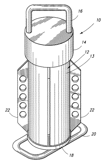
Fig. 1 is an isometric view of the exterior of the disclosed invention.
Fig. 2 is an exploded isometric view of the disclosed invention
Fig. 3 shows a side view of the exterior of the disclosed invention.
Fig. 4 shows a side view of the internal components of the disclosed
invention.
Fig. 5 shows a top view of the exterior of the disclosed invention.
Fig. 6 shows a bottom view of the exterior of the disclosed invention.
DETAILED DESCRIPTION OF THE EMBODIMENTS
As shown in FIG. 1, the exterior components of the shrouded magnet 10 are a
container 12 having an opening, and an outer surface 13, a cap 14 for sealing
the container,
and a base 18. While the shrouded magnet 10 may be placed in the fluid stream
in any
orientation, the operator may find that it is most convenient to place the
device with the
longitudinal axis of the container 12 perpendicular to the direction of fluid
flow, so that the
device is standing on the base 18. When standing on the base 18, the stability
of the device
may be increased by attaching a base extension 20 to the base 18. It may also
be desirable to
CA 02443111 2003-10-06
WO 02/083264 PCT/US02/10498
6
attach flow vanes 22 to the container 12, so that the long axes of the flow
vanes are oriented
generally parallel to the longitudinal axis of the container 12. The flow
vanes 22 may have
fluid passages, such as holes, to direct fluid flow around the outer surface
13 of the container
12.
As shown in FIG. 2, the internal components of the shrouded magnet 10 include
a
plurality of iron magnets 28 disposed within the container 12. However, any
means for
creating a magnetic field extending through the container 12 to the outer
surface 13 will
accomplish the required purpose, including the iron magnets 28, magnetic
alloys or an
electromagnet comprised of an iron core surrounded by a current-carrying coil.
If an
electromagnet is used, a means of producing electrical current is required.
Such means may
include either a direct current source such as a battery or an alternating
current source such as
a generator or utility power. A battery may be inserted inside the container
12, thereby
requiring no external leads to the coil. If an alternating current source is
used, external leads
to the coil will be required and the leads must be introduced into the
container 12 so as to
maintain a fluid-tight seal within the container, by methods well known in the
industry.
The container 12 should be constructed of a non-magnetic material such as
aluminum,
fiberglass or plastic. The use of non-magnetic materials for the container 12
prevents the
container from becoming magnetized, thereby allowing any magnetic materials
attached to
the outside surface 13 of the container to disengage when the magnets 28 are
removed from
within the container 12.
In the embodiment shown in FIG. 2, a plurality of magnets 28 are disposed in
facing
relation. Each magnet 28 has a bore such that the bores of adjacent magnets 28
are aligned
along the vertical axis of the container 12, so that the outside edge of each
magnet is adjacent
to the inner peripheral surface 36 of the container 12, resulting in the
creation of a magnetic
field extending to the outside surface 13 of the container 12. As shown in
FIG. 2 and FIG. 4,
a retention rod 30, having a bottom end 32 and a top end 34 may be inserted
through the
bores of the magnets 28. A stop collar 38 or other type of retaining device
may be affixed to
the bottom end 32 of the retention rod 30, which will allow the removal of all
of the magnets
28 from the container 12 simply by removing the retention rod 30. The top end
34 of the
retention rod 30 may be attached to the inside surface of the cap 14, so that
removal of the
cap 14 and pulling upwards will also remove the retention rod 30, the magnets
28, and the
CA 02443111 2003-10-06
WO 02/083264 PCT/US02/10498
7
stop collar 38. As shown on FIG. 3, a receptacle 33 may be fashioned on the
inside surface of
the base 18 for receiving and stabilizing the bottom end 32 of the retention
rod 30.
It has been found that if all of the magnets 28 within the container 12 are
oriented so
that the polarities (i.e., the north pole and south pole) of each magnet 28
are facing in the
same direction, metal particles recovered from the drilling fluid tend to
concentrate at that
portion of the outside surface 13 of the container 12 where the magnetic field
is the strongest.
However, as shown in FIG. 4, the magnets 28 may be placed in groups, such that
each
magnet 28 in a group is oriented so that the polarities of each magnet in the
group are facing
the same direction, but the polarity of each group within the container 12 may
be different
from an adjacent group. For example, if three groups of magnets 28 are formed,
the north
magnetic pole of the top group 42 may be oriented facing the top end 34 of the
retention rod
30 and the south pole oriented facing the bottom end 32; the south magnetic
pole of the
middle group 44 may be oriented facing the top end 34 and the north pole
oriented facing the
bottom end 32; and, the north pole of the bottom group 46 may be oriented
facing the top end
34 and the south pole oriented facing the bottom end 32. Alternating the
magnetic polarity of
each group of magnets 28 will result in distributing metal fragments recovered
from the
drilling fluid to be more evenly distributed on the outside surface 13 of the
container 12,
allowing a larger accumulation of metal fragments before removal of the
fragments is
required. Each group of magnets 28 may be separated by a spacer 40.
The cap 14 may be equipped with a handle 16 to assist the user in lifting or
otherwise
maneuvering the device. The container 12 should be equipped with sealing means
24, such
as threads and/or "0" rings and the cap 14 should have matching sealing means
26, such as
threads and/or "0" rings to prevent fluid flow into the interior of the
container 12.
Using the-invention disclosed herein, a method has been developed for removing
metallic casing fragments from fluids discharged from an oil or gas well. In
this method,
magnetic casing fragments are removed from fluids discharged from an oil or
gas well by
passing the fluids through a magnetic field created by a shrouded magnet 10.
The shrouded
magnet 10 contains magnets 28 contained within a nonmagnetic container 12,
which act to
separate the casing fragments and other magnetic materials from the well
fluids. Upon
accumulation of the metallic casing fragments upon the outside surface 13 of
the container
12, the shrouded magnet 10 is removed from the fluids and the magnets 28 are
removed from
CA 02443111 2003-10-06
WO 02/083264 PCT/US02/10498
8
the nonmagnetic container 12, so that the magnetic field attracting the casing
fragments is
removed and the casing fragments may be released and collected.
Using the invention disclosed herein, a method has been developed for
analyzing
casing wear and making determinations of the casing integrity. In this method,
as described
above, magnetic casing fragments are removed from fluids discharged from an
oil or gas well
by passing the fluids through a magnetic field created by the shrouded magnet
10, having
magnets 28 contained within a nonmagnetic container 12, which act to separate
the casing
fragments and other magnetic materials from the well fluids. Upon accumulation
of the
metallic casing fragments upon the outside surface 13 of the container 12, the
shrouded
magnet 10 is removed from the fluids and the magnets 28 are removed from the
nonmagnetic
container 12, so that the magnetic field attracting the casing fragments is
removed and the
casing fragments may be released and collected. The collected casing fragments
are thereafter
weighed and a total weight for all collected fragments is calculated. The
total weight of the
casing originally installed in the well is also calculated, based upon either
recorded weights
for each individual length of casing, or upon casing tables providing the
weight per foot for
the particular size and grade of casing. The percent of metal loss from the
casing may then be
calculated by dividing the total weight of the casing fragments recovered from
the well by the
total weight of the casing originally installed in the well.
The casing fragments are also visually examined to ascertain the nature of the
casing
wear. For example, large sections of casing wall with tool marks may call into
question the
integrity of the casing, but a small volume of small shavings may indicate
uniform wear in
the casing. Depending upon the material used for each length of casing, visual
inspection
may allow the determination of the particular casing string from where a
particular casing
fragment came. The location of a problem area may also be approximated by the
depth of the
drill pipe or tool string at the time the fragment is accumulated at the
shrouded magnet, the
volume of fluid within the well, and the displacement and speed of the pumps
circulating the
fluid.
While the above is a description of various embodiments of the present
invention,
further modifications may be employed without departing from the spirit and
scope of the
present invention. For example, the size, shape, and/or material of the
various components
may be changed as desired. Thus the scope of the invention should not be
limited by the
CA 02443111 2003-10-06
WO 02/083264 PCT/US02/10498
9
specific structures disclosed. Instead the true scope of the invention should
be determined by
the following claims.