Note: Descriptions are shown in the official language in which they were submitted.
CA 02443755 2003-10-22
1
TITLE OF THE INVENTION:
Combination Shipping Container and Display Rack
FIELD OF THE INVENTION
The present invention relates to a combination shipping
container and display rack.
BACaC.GROUND OF THE INVENTION
A -retailer distribution channel for goods always starts
with a manufacturer and ends with a retailer. There are
frequently, but not always, middlemen between the manufacturer
and the retailer.
Every time goods must be handled along the distribution
channel, an expense is incurred. This expense must ultimately
be recouped and will, therefore, be reflected in the price
that a consumer pays for the goods.
SUd~IMARY OF THE INVENTION
what is required is a shipping container that the
manufacturer uses to ship the goods that upon reaching its
ultimate destination can be used by the retailer to display
the goods.
According to the present invention there is provided a
combination shipping container and display rack which includes
a parallel-piped body having a top, a bottom, and four sides.
A plurality of container receiving cavities are accessible
from at least one of the four sides into the body. A
container is disposed in each of the container receiving
cavities. Each container is just slightly smaller than a
container receiving cavity in which it is received. Each
container has a front panel divided into an upper portion and
a lower portion. The upper portion is either movable or
removable in order to provide access to goods within the
container during retail display. A closure panel overlies the
accessible side of the body, thereby shielding the containers
CA 02443755 2003-10-22
2
during transport. Wheels are mounted to the bottom of the
body, whereby the body can be rolled across an underlying
surface. A pair of forklift tine receptacles are mounted in
parallel spaced relation to the bottom of the body, whereby
the body can be lifted by inserting tines of a forklift into
the forklift tine receptacles.
The described combination is first used by the
manufacturer as a shipping container. Containers filled with
goods are inserted into the container receiving cavities. The
closure panel is placed across the side by which the container
receiving cavities are accessed, in order to secure the
containers during transport. The body is lifted onto
transport vehicles by means of a forklift which inserts its
tines into the forklift receiving cavities. The described
combination is subsequently used as a display rack. The
protective closure panel is removed. The upper portion of the
front panel of each container is either moved or removed to
provide better sight lines and access to goods within the
containers. The body is then rolled out into the retail
display area on its underlying wheels.
Although beneficial results may be obtained through the
use of the combination, as described above, there will now be
described additional features which further increase the
utility of the combination. Tracking shipments has become a
matter of increasing concern. It is, therefore, preferred
that the body have external electronically readable
identification. Inventory control is also a matter of
increasing concern. It is, therefore, preferred that the
front panel of each container has electronically readable
identification.
Although beneficial results may be obtained through the
use of the combination, as described above, where the goods
are fragile it is preferred that means be provided for locking
each individual container to the body. This can be done by
CA 02443755 2003-10-22
3
equipping each individual container with opposed locking
receptacles which engage locking members on the body.
Beneficial results have been obtained when the locking members
are hooks and the receptacles are eyelets which are adapted to
receive the hooks.
Although beneficial results may be obtained through the
use of the combination, as described above, storage space is
usually at a premium in retail premises. Even more beneficial
results may, therefore, be obtained when the closure panel has
a transport position and a display position. In the transport
position, the closure panel overlies the accessible side of
the body and closes the container receiving cavities. In the
display position the closure panel is spaced from and provides
full access to the container receiving cavities. For shopping
mall kiosk locations, the closure panel can be placed in its
display position during the day and returned to and locked in
its transport position at night. Beneficial results have been
obtained when the closure panel is foldable and can fold out
of the way for its display position.
Although beneficial results may be obtained through the
use of the combination, as described above, it is highly
desirable to have the goods in the containers as visible as
possible when the goods are on retail display. Even more
beneficial results may, therefore, be obtained when each
container is made from wire mesh construction that consumers
can view the goods through.
Although beneficial results may be obtained through the
use of the combination, as described above, it is highly
undesirable for any of the containers to fall out of their
container receiving cavity during movement of the display rack
within the retail display area. Even more beneficial results
may, therefore, be obtained when a mouth of each of the
container receiving cavities has a lower containment lip" such
that each container must be lifted over the containment lip in
CA 02443755 2003-10-22
4
order to remove the container from its container receiving
cavity. In order to further improve visibility, each container
receiving cavity can be made accessible from two opposed
sides.
BRIEF DESCRIPTION OF THE DRAWINGS
These and other features of the invention will become
more apparent from the following description in which
reference is made to the appended drawings, the drawings are
for the purpose of illustration only and are not intended to
in any way limit the scope of the invention to the particular
embodiment or embodiments shown, wherein:
FIGURE 1 is a front elevation view of a combination
shipping container and display rack constructed in accordance
with the teachings of the present invention, with containers
and closure panel removed.
FIGURE 2 is a front elevation view of the combination
shipping container and display rack illustrated in FIGURE 1~
with some containers inserted into the container receiving
cavities.
FIGURE 3 is a top plan view, in section, of the
combination shipping container and display rack illustrated in
FIGURE 1 with foldable closure panels.
FIGURE 4 is a detailed front elevation view of the
combination shipping container and display rack illustrated in
FIGURE 1.
FIGURE 5a is a detailed side elevation view, in section,
of the combination shipping container and display rack
illustrated in FIGURE 4.
FIGURE 5b is a detailed front elevation views, in
section, of the combination shipping container and display
rack illustrated in FIGURE 4.
FIGURE 6 is a detailed front elevation view of a
container from the combination shipping container and display
rack illustrated in FIGURE 1.
FIGURE 7 is a detailed front elevation view of a locking
member and opposed locking receptacle of the combination
CA 02443755 2003-10-22
shipping container and display rack illustrated in FIGURE 6.
FIGURE 8 is a perspective view of a container from the
combination shipping container and display rack illustrated in
FIGURE 6, with upper portion removed to facilitate display.
5
DETAILED DESCRIPTIOIvY OF THE PREFERRED EMBODIMENT
The preferred embodiment, a combination shipping
container and display rack generally identified by reference
numeral 10, will now be described with reference to FIGURES I
through 8.
Structure and Relationship of Parts:
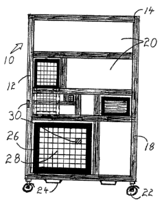
Referring to FIGURE l, combination shipping container and
display rack 10 has a parallel-piped body 12 having a top 14,
a bottom 16 and four sides 18. A plurality of container
receiving cavities 20 are configured within parallel-piped
body 12 such that they are accessible from two opposed sides
18. Referring to FIGURES I and 2, wheels 22 and forklift tine
receptacles 24 are mounted to bottom 16 of parallel-piped body
12. Referring to FIGURE 2 and 4, each of container receiving
cavities 20 has disposed within it a container 26. Four
containers 26 are illustrated, each having a mesh construction
28. Parallel-piped body 12 and each of container 2& has an
electronically readable identification 30. Referring to
FIGURE 3, combination shipping container 10 is further
adapted with foldable closure panels 32 shown in display
position. Referring to FIGURES 5a and 5b, each of container
receiving cavities 20 has a lower containment lip 34.
Referring to FIGURE 6, locking members 36 in the form of hooks
are mounted on parallel-piped body 12 and situate on opposed
sides of each of container receiving cavity 20. Referring to
FIGURE 7, opposed locking receptacles 38 in the form of
eyelets are on each of container 20, engaging locking members
36. Referring to FIGURE 8, each of container 20 has a front
panel 40 with an upper portion 42 and a lower portion 44.
Upper portion 42 is shown in an access position.
CA 02443755 2003-10-22
0
Operation:
The use and operation of Combination Shipping Container
and Display Rack 10 in accordance with the teachings of the
preferred embodiment will now be described with reference to
FIGURES 1 through 8. Referring to FIGURE 8, a shipper, wishing
to transmit goods to a distribution or retail outlet, loads
goods into containers 26 via upper portion 42 of each of
container 26. Referring to FIGURES 1. and 2, loaded containers
26 are then installed into appropriate container receiving
cavities 20 of parallel-piped body 12. Referring to FIGURES 3
and 4, once all the desired goods are loaded, the appropriate
electronically readable identification 30 is fixed to
parallel-piped body 12 and each of container 26 and foldable
closure panels 32 are placed in transport position. Referring
to FIGURES 5a, 5b and 6, further security of the goads is
provided by placing each of container 26 behind lower
containment lip 34 and by engaging locking members 36 and
opposed locking receptacles 38 as spawn in FIGURE 7.
Referring to FIGURES 1 and 2, from this point on, combination
shipping container and display rack 10 is handled and placed
into transport by forklift tine receptacles 24. Upon arrival
at a distribution or retail location, combination shipping
container and display rack 10 is rolled into a desired
position on wheels 22. Referring to FIGURE 7, locking members
36 are disengaged from opposed locking receptacles 38.
Referring to FIGURE 8, upper portion 42 of each of container
26 is opened and the goods are thus made accessible for public
inspection and consumption.
In this patent document, the word "comprising" is used in
its non-limiting sense to mean that items following the word
are included, but items not specifically mentioned are not
excluded. A reference to an element by the indefinite article
"a" does not exclude the possibility that more than one of the
element is present, unless the context clearly requires that
there be one and only one of the elements.
CA 02443755 2003-10-22
It will be apparent to one skilled in the art that
modifications may be made to the illustrated embodiment
without departing from the spirit and scope of the invention
as hereinafter defined in the Claims.