Note: Descriptions are shown in the official language in which they were submitted.
CA 02443819 2003-10-09
WO 02/089902 PCT/US02/14157
APPARATUS AND METHODS FOR DELIVERY OF TRANSCRANIAL
MAGNETIC STIMULATION
BACKGROUND OF THE INVENTION
Field of the Invention
The present invention is directed to apparatus and methods particularly
suitable
for precise aiming and delivery of magnetic stimulation, and more
specifically,
transcranial magnetic stimulation.
Description of the Related Art
Transcranial magnetic stimulation ("TMS") is a means of repetitively
stimulating
the human brain through an intact scalp and skull, i.e., non-invasively. TMS
is delivered
by passing a brief (200 microsecond), strong (10,000 volts, 6,000 amps)
electrical current
through a coil of wire (a TMS stimulator) placed adjacent to the head. The
passage of
electrical current induces a strong (2 Tesla) magnetic field which, in turn,
induces
electrical currents in nearby tissues. In the case of nerve cells, if the
induced current is
sufficiently intense and properly oriented, it will result in synchronized
depolarization of
a localized group of neurons (i.e., neuronal "firing"). Initially, magnetic
stimulation was
used only for peripheral nerves, in which instance it is affecting nerve
fibers rather than
neuronal cell bodies. More recently (Barker et al., 1985), magnetic
stimulation has shown
to be able to depolarize neurons in the brain. The cellular element of the
brain being
affected by TMS was assumed, but not proven, to be fibers rather than neuronal
cell
bodies.
TMS has several present and potential applications, in the domains of basic
neuroscience research and of the treatment of brain disorders. Applications
for
neuroscience research include, for example: imaging brain connectivity (e.g.,
Fox et al.,
1997); establishing inter-regional and inter-hemispheric conduction times
(e.g., Meyer et
al., 1995); testing the function of specific brain areas by means of transient
functional
disruptions, so-called "virtual lesions" (e.g., Shipley & Zeki, 1995); and,
studying the
modification of synaptic efficacy induced by repetitive stimulation, termed
LTP (long-
term potentiation) and LTD (long-term depression). Potential clinical
applications
include, for example: pre-operative mapping, e.g., of language related brain
areas
(Epstein (et al., 1996); testing for neuronal conduction delays due to
dysmyelinating
disorders; and, treating brain disorders by selective modification (up or down
regulation)
-1-
CA 02443819 2003-10-09
WO 02/089902 PCT/US02/14157
of the synaptic efficacy of pathways (i.e., by inducing LTP and LTD; Wang,
Wang and
Scheich, 1996).
At present, TMS delivery is crude. The TMS effector or stimulator (commonly
referred to as a "TMS coil")is a wire-wound coil, typically shaped like a "B."
The B-
shaped coil is placed against the scalp and held in place by a human operator.
For the
primary motor cortex and primary visual cortex (small sections of the total
brain surface),
proper positioning is established by the elicited response: muscle
contractions when
stimulating the primary motor cortex; illusory lights (phosphenes) when
stimulating the
primary visual cortex. In both of these areas, the effects are very sensitive
to coil position
and orientation.
For brain regions in which proper positioning cannot be determined by the
induced effects (i.e., muscle contractions or subjective experience), position
is generally
determined by reference to a traditional pattern used for placement of EEG
electrodes
(10/20 system). The 10/20 system is based on scalp/skull landmarks which do
not bear a
reliable relationship to the functional anatomy of the brain. Further, when
using the 10/20
system, there has been no strategy enunciated for determining proper
orientation of the
coil. Thus, a reliable method for determining the proper position and
orientation of TMS
coil placement for brain areas lacking immediately observable feedback is
needed.
Application of TMS during radionuclide imaging (using positron-emission
tomography ("PET") or single photon emission tomography ("SPECT")) has two
important uses. First, radionuclide imaging can be used to monitor the induced
response,
determining precise location and quantifying response magnitude. This is
extremely
important for testing aiming algorithms and for determining the effect of
stimulation
parameters, such as intensity, rate, duration and the like. Second, an
important use of
TMS is to map brain connectivity using radionuclide imaging. For both of these
applications, hand-held TMS delivery is inappropriate, for at least three
reasons. First,
hand-held delivery is unsafe, unnecessarily exposing the experimentor to the
radiation
used for imaging. Second, hand-held delivery is positionally unstable,
degrading image
quality by small movements of the holder. Third, hand-held delivery is
intrinsically
inaccurate and imprecise.
Further, current coil designs for delivery of TMS have been mainly intuitive
and
somewhat crude. Typical coil designs consist of two loop figure eight type
coils, for
peripheral nerve and brain stimulation, four loop coils for peripheral nerve
stimulation,
-2-
CA 02443819 2003-10-09
WO 02/089902 PCT/US02/14157
and variations in angles of these. While attention is paid to coil inductance,
it is only for
simple circuits that this may be easily calculated.
The target field method has been used to produce minimum inductance
cylindrical
gradient coils for MRI (Turner, 1986) and has been adapted for bi-planar coils
(Martens
et al., 1991). Minimum power designs have also been presented (Bowtell et
al.).
However, such design methods have not been applied to the design of magnetic
stimulation coils.
Various combinations of circular or rectangular coil shapes have been
designed.
Figure eight type designs appear to be the most common. Further, B-shaped and
slinky-
type coils have also been designed (Cadwell; Lin et al.). Sections of toroids
(Davey,
Epstein, Carbunaru) with magnetically permeable cores are also known, and
appear to be
an efficient design. However, none of these provide an extremely focused field
penetration. Two and four wing coils with a straight section joined with
curves for
peripheral nerve stimulation have been designed. (Ruohonen et al.) However,
these
designs are largely limited by intuition.
Thus, fundamental limitations on the utility of TMS for research and treatment
include a lack of methods for precise, automated aiming (positioning and
orienting) and
safe, rigid (i.e., non-human) holding of the TMS stimulator, as well as the
poor suitability
of present coils for TMS.
SUMMARY OF THE INVENTION
The present invention enhances the precision and ease with which TMS may be
used for the diagnosis and treatment of neurological and psychiatric disorders
and for
neuroscience research. In certain embodiments, these benefits may be
accomplished via
use of specifically shaped TMS stimulators having certain properties. In
certain
embodiments, a robot, such as a neurosurgical robot, may be used to deliver
TMS. The
present invention also includes algorithms for treatment planning and
treatment delivery,
including: algorithms for rapidly modeling the 3-D electric field created in
the brain by a
TMS coil at any external location; cortical surface modeling (extraction and
visualization); scalar product (electric-field vector times cortical-surface
vector)
computation and visualization; and merging of functional images, structural
images and
treatment-planning models (surfaces & fields).
The present invention further includes treatment-delivery tools such as
frameless
registration of head, brain image, and robot; fully automated robotic
positioning of the
-3-
CA 02443819 2003-10-09
WO 02/089902 PCT/US02/14157
TMS coil; robotic sensing of TMS orientation (about a manually operated tool-
rotation
axis); hardware extensions including a passive digitizing arm; a TMS tool
mount; a
passive tool-rotation axis with an orientation sensor; and a general-purpose
mobile cart.
Additionally, inventive methods enhance the precision and ease with which TMS
may be used for neuroscience research and for the diagnosis and treatment of
neurological and psychiatric disorders.
The inventors have determined that the biological efficacy of transcranial
magnetic stimulation applied to cerebrum can be estimated at any point as the
scalar
product of the induced electrical field (E, a vector) and a unit vector
aligned parallel to
the cortical columns. The unit vector is estimated as a normal (i.e.,
perpendicular) the
cortical surface, as this is the known orientation of cortical columns. The
biological
efficacy of a TMS E field, then, is calculated using equation 1.
Biological efficacy = JEl cos 0 P]
]
where 0 is the angle between E and the unit normal vector. This Cortical
Column
Cosine Aiming Principle ("CCCAP" or "CAPS" or "aiming principle") is based on
the
inventors' determination that the cortical column is the biological unit of
the brain with
the lowest threshold for TMS excitation and the well-established neuro-
anatomical
principle that the cortical columns are oriented at a right angle to the
cortical surface.
Thus, maximum biological efficacy of a cortical region of interest occurs
where the
induced E field is parallel to the direction of the cortical columns, i.e.,
normal to the
cortical surface.
The CCCAP includes the following principles: (1) surface grey matter (the
cortex) is preferentially or exclusively activated; axons in the sub-cortical
white matter
are minimally activated by the TMS-induced E-field, but will conduct action
potentials
initiated in cortex by TMS; (2) cortical grey matter will be most effectively
activated by
an E-field oriented parallel to the columnar organization of the cortex; (3)
the response
magnitude at any cortical location is a function of the magnitude of the E-
field parallel to
the cortical columns; (4) cortex is preferentially (but not exclusively)
activated by
orthodromic E-fields, passing from the pial surface, through the soma, to the
sub-cortex;
antidromic E-fields, passing toward the pial surface will be less effective
but not
ineffective; and (5) the orientation of the cortical columns is
macroscopically estimated as
the normal to the true cortical surface. Of the five aiming principles, the
first two
(particularly the second) are strongly at odds with current opinion and
practice in the
-4-
CA 02443819 2003-10-09
WO 02/089902 PCT/US02/14157
TMS community. It is to be understood that a true cortical surface is one
derived from an
anatomical image with sufficient spatial resolution and image contrast to
define the cortical-
subcortical or cortical-CSF border. Simplified (e.g., spherical) models or
generalized models
of the cortex which do not define the true cortical surface may not accurately
model the
orientation of the cortical columns.
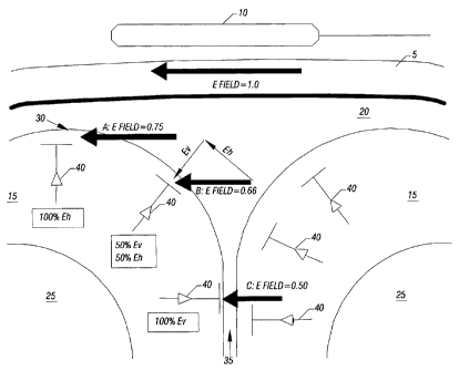
FIG. 1 is a cross-sectional view of a subject's head 5 with a B-shaped coil 10
positioned thereabove. As shown, the head includes the scalp and skull 5, the
cerebral cortex
or grey matter 15, cerebrospinal fluid (CSF) 20, and white matter 25. Where
the cortex is
concave, folding inwardly away from the scalp and skull, it is termed a sulcus
35 (pl. such).
For present modelng purposes, the most important components of the cortex are
the vertical
neurons 40, which are oriented perpendicular to the brain's cortical surface
(i.e.,
perpendicular to the interface between cortex 15 and CSF 20). The vertical
neurons
collectively form the cortical columns (not shown), which are the dominant
anatomical and
physiological features of cerebral cortex (at the microscopic level), being
present in all
regions of cortex in all mamallian species. (Only a few vertical neurons are
illustrated in
Figure 1).
In FIG. 1, the TMS coil 10 is positioned and oriented to create an induced E-
field that
is perpendicular to the brain cortical surface (and parallel to the vertical
neurons) in the
sulcus (C), but parallel to the cortical surface (and perpendicular to the
vertical neurons) at
the crown of the gyrus (A). The magnitude of the E field is weaker at C than
at A, because
the distance from the surface of the TMS coil 10 is greater at C than at A.
Relative to the
orientation of the vertical neurons forming the cortical columns the E field
can be
decomposed into vertical (E,,) and horizontal (Eh) components, which are
parallel to the
vertical neurons and horizontal fibers, respectively. By Principal (2),
activation at any
cortical site is a function of E,, with negligible Eh effect. Thus, E has no
effect (no E,,
component) where E is perpendicular to the column (A); intermediate effects
for intermediate
relative orientations (B); and maximal effect where E is parallel to the
column (C).
Prior art (Brasil-Neto et. al 1992; Mills et al., 1992) has empirically
demonstrated that
coil orientation computed in the manner just described is optimal for one
brain area (the
primary motor cortex), but provided a rationale not applicable to brain
regions other than
primary motor cortex and inconsistent with the above explanation.
-5-
SUBSTITUTE SHEET (RULE 26)
CA 02443819 2003-10-09
WO 02/089902 PCT/US02/14157
In an example embodiment, the CCCAP may be used to allow the cortical
excitation effects of TMS to be computed in advance for any position and
orientation,
thereby enabling computer-aided aiming of TMS. However, in other embodiments,
the
CCCAP may be used for manual aiming and orienting. The CCCAP may also be used
to
normalize (correct) observed biological effects for the angle of intersection
with the
cortex, when aiming is done conventionally (i.e., not with CCCAP) but images
are
obtained showing the relationship between the TMS coil and the cortical
surface.
In an example method, image-guided, computer-aided implementation of the
CCCAP for TMS delivery may be effected in accordance with the following steps.
First,
an imaging stage is performed, in which a high-resolution, anatomical image
(e.g., a 3D
TI-weighted image) of the subject's head is obtained. Preferably, sufficient
grey-white
contrast is obtained to allow detailed cortical-surface segmentation. Next, a
functional
image (either functional MRI or PET, for example) data set is obtained during
conditions
(task/control pair) which selectively activate the cortical region of interest
(e.g., repetitive
hand movement to activate the supplementary motor area).
Next, a modeling stage is performed to identify surfaces within the anatomical
and functional images, to be used for registration of the functional and
anatomical images
to one another and, subsequently, to the patient. In the anatomical image
(e.g., an
anatomical MRI), the scalp surface and the brain's cortical surface are
segmented and
modeled as polygon-mesh surfaces. The brain-surface is modeled at high-
resolution, to
provide an accurate, detailed representation of the interface between
cerebrospinal fluid
(CSF) and cortical grey matter, as this is critical for establishing the
orientation of the
cortical columns. Anatomical surface extraction and modeling is done in a
manner
keeping both surface models (scalp and brain) in register with the original
image and,
thereby, with one another. In the functional image (either PET or fMRI), the
brain
surface is segmented and modeled as a polygon mesh surface (but with less
detail than
the model derived from the anatomical image) and the targeted site is
identified. The two
brain surface models (anatomical-image-derived and functional-image-derived)
are co-
registered, thereby bringing the target site in register with the two MRI-
derived cortical
surface models: brain and scalp. This comprises a conjoined
functional/anatomical
model.
Then, a 3-D model of the TMS-coil's physical surface and the 3-D E-field
induced
by the TMS coil is created, and this TMS coil-surface/E-field model is
superimposed on
-6-
CA 02443819 2003-10-09
WO 02/089902 PCT/US02/14157
the conjoined functional/anatomical model. The TMS coil-surface/E-field model
is
positioned and oriented so as to obtain maximum biological efficacy (as
defined by the
CCCAP) at the target point, while keeping the coil surface outside the scalp
surface. The
position and orientation of the TMS coil-surface relative to the conjoined
functional/anatomical model may then be stored for subsequent use.
In an example embodiment, this data may be used to perform TMS delivery in
accordance with the following. First, the subject is placed in the treatment
position and
the head immobilized, for example, using a thermoplastic mask (Fox et al.,
1985). With
the subject in the treatment position, a 3-D digitizer (e.g., a passive arm
digitizer) may be
used to collect a series of points on the scalp surface. These points are used
to create a
model of the scalp surface in the subject's current head position. This model
is registered
to the conjoined functional/anatomical model previously created, using a
rapid, surface
matching algorithm, such as a convex hull algorithm (Lancaster et al., 1999).
The manual
digitizer may again be used to collect a set of specific reference points on
the surface of
the TMS coil, which may be mounted on a multi joint, calibrated armature,
either passive
or robotic.
As the optimal position for the TMS to achieve supra-threshold stimulation of
the
target location has been previously computed, the translations and rotations
needed to
move from the present position to the desired position are computed. If the
TMS is held
by a passive armature, movement is executed manually, with the readout of the
coordinates of the an-nature as feedback. If the TMS is held by a robot,
movement is
executed automatically, after a safe pathway (avoiding contact with the
subject or other
obstacles) has been computed. When properly positioned and oriented, TMS
delivery is
effected.
The advantages of this method are several. First, placement is extremely
precise
( 1 mm), much more precise than is possible using hand-held aiming. Second,
placement
can be computed in advance, rather than by trial-and-error, as is done with
hand-held
aiming for areas with a measurable behavioral response. Third, once computed,
a position
can be precisely re-established for subsequent treatments. Fourth, the entire
process is
mathematically specified and suitable for computer implementation. Fifth, the
procedure
is suitable for application to any cortical location, not just brain areas in
which aiming
accuracy can be confirmed by an overt behavioral response. Sixth, once the
necessary
-7-
CA 02443819 2003-10-09
WO 02/089902 PCT/US02/14157
brain images are acquired, trajectories for stimulating any number of
functional areas can
be computed.
In an example embodiment, TMS delivery may be effected by means of a robotic
arm. Using a robotic arm to move, aim and hold the TMS provides many benefits.
First, a
robotic arm allows the TMS coil to be placed and oriented with accuracy and
precision of
- 1 inm (location) and -- 1 (orientation), far exceeding hand-holding. This
degree of
accuracy and precision is crucial for implementing a high-precision aiming
algorithm.
Second, a robotic arm allows the TMS to be positioned automatically, i.e.,
under
computer control. Third, a robotic arm allows the TMS to be positioned
rapidly, saving
time for the patient, experimentor or clinician. Fourth, a robotic arm can
accurately re-
establish its position on sequential days, which is needed for experiments and
treatments
applied over a series of sessions. Fifth, a robotic arm allows the TMS to be
moved rapidly
from one position to another, allowing treatment of more than one location in
a single
session. Sixth, a robotic arm allows the TMS to be held immobile for long
periods of
time, which a person cannot practically or comfortably achieve. Seventh, a
robotic arm
allows TMS to be delivered during PET imaging, without exposing a human holder
to
radiation.
The present invention is also directed to an inverse design method to produce
a
desired electric field profile for transcranial/peripheral nerve magnetic
stimulation. Such
a method may be used to design a variety of coils. Such coils may include
multiple
winged coils having a concentrated bundle of wires at the center and smooth
arcs splayed
therefrom at an increasing distance, maintaining the minimum inductance and/or
minimum power dissipation possible for a given field profile. Similarly, other
coils may
be used to produce a spatial gradient across the nerve, maintaining minimum
inductance
and/or minimum power dissipation.
Coils may be designed in accordance with the teachings of the present
invention
to incorporate one or more of the following characteristics which aid in the
delivery of
transcranial magnetic stimulation. In certain embodiments, a coil may be
designed to
provide for minimum inductance for a given set of field constraints. Further,
a coil may
be designed to dissipate a minimum amount of power for a given set of field
constraints.
Similarly, a coil may be designed to provide for minimum inductance and
minimum
dissipation for a given set of field constraints. In certain embodiments, a
coil may be
-8-
CA 02443819 2008-12-02
designed with negative turns to reduce the electric field on a patient. Such
negative turns also
may be provided in a separate layer to similarly reduce electric field on the
patient.
In one aspect, the invention resides in a system comprising a robotic arm
having a
distal end and a proximal end and a magnetic stimulator coupled to the distal
end of the
robotic arm.
In another aspect, the invention resides in a system comprising an active
member
capable of movement under machine control, the active member having a distal
portion and
a proximal portion and a transcranial magnetic stimulator coupled to the
distal portion of the
active member, the transcranial magnetic stimulator to provide magnetic
stimulation to a
subject.
In still another aspect, the invention resides in a system for transcranial
magnetic
stimulation, comprising: a robotic member having a distal portion and a
proximal portion,
said robotic member having at least six degrees of freedom; a coil for
generating an electric
field, said coil coupled to said distal portion of said robotic member; a
computer to control
movement of said robotic member to position said coil at a preselected
position relative to a
subject according to a pre-specified treatment plan for magnetic stimulation
in accordance
with an aiming principle; and a storage coupled to the computer and storing
the pre-
specified treatment plan.
In a further aspect, the invention resides in a coil for transcranial magnetic
stimulation, comprising a solid former having a hollow portion extending
therethrough on a
long axis of said former; and a wire winding wrapped around said long axis and
extending at
least substantially around said former, wherein said wire winding is wrapped
in a toroidal
manner through the hollow portion of said former and the coil is configured to
generate a
maximum induced electric field extending along the long axis.
In yet a further aspect, the invention resides in a system comprising a
moveable
member having a distal end and a proximal end; a magnetic stimulator coupled
to the
distal end of the moveable member and a controller coupled to the moveable
member to
control positioning of the magnetic stimulator.
-9-
CA 02443819 2008-12-02
BRIEF DESCRIPTION OF THE DRAWINGS
The present invention may be better understood, and its numerous objects,
features, and advantages made apparent to those skilled in the art by
referencing the
accompanying drawings.
FIG. 1 is a cross sectional diagram of a subject's brain and a B-shaped TMS
stimulator positioned thereabove having an induced electric field parallel to
the short axis of
the coil.
FIG. 2 is a diagram of a typical current configuration for an 0-shaped coil.
FIG. 3 is a diagram of a typical current configuration for a B-shaped coil.
FIG. 4 is a simplified top view of TMS coil orientations used in a prior art
study
of primary motor cortex.
FIG. 5 is a simplified top view of TMS coil orientations used in a prior art
study.
FIG. 6 is a graph of the results of delivering TMS during PET applied to the
foot
area of primary motor cortex at 0 (perpendicular to cortex), 300, 60 , and 90
(parallel to
cortex).
FIG. 7 is an isometric view of an example TMS stimulator according to the
present invention.
FIG. 8 is a diagram of a TMS attached to a robot and placed behind a PET
scanner,
to acquire a PET functional imaging study during TMS stimulation. The upper
right
quadrant of the PET is shown in a cut-away view, to allow the robotic TMS
system to be
illustrated.
FIG. 9 is an isometric view of a TMS tool holder according to the present
invention.
FIG. 10 is a flow diagram of an example TMS treatment planning system
according to
the present invention.
FIG. 11 is a flow diagram of an example TMS treatment delivery system
according to
the present invention.
FIG. 12 is a representation of a TMS coil in accordance with the present
invention.
FIG. 13 is a representation of a TMS coil in accordance with the present
invention.
-9a-
CA 02443819 2003-10-09
WO 02/089902 PCT/US02/14157
FIG. 14 is a diagram of an alternate coil embodiment according to the present
invention.
FIG. 15 is a graphical representation of the electric field magnitude/current
of the
coil of FIG. 14 along the x-axis.
FIG. 16 is a graphical representation of the electric field magnitude/current
of the
coil of FIG. 14 along the y-axis.
FIG. 17 is a diagram of an alternate coil embodiment according to the present
invention.
FIG. 18 is a close up view of the center portion of the coil shown in FIG. 17.
The use of the same reference symbols in different drawings indicates similar
or
identical items.
DESCRIPTION OF THE PREFERRED EMBODIMENT(S)
Aiming is the most fundamental, unresolved issue for scientific and medical
uses
of TMS. TMS is most often "aimed" merely by observing its behavioral effects.
For
example, primary motor cortex is frequently identified by adjusting coil
position/orientation to achieve a contraction of the desired muscle (e.g.,
abductor pollicis
brevis) at the lowest stimulus voltage. Very recently, image-guided aiming has
been
introduced (below). Even when image-guided, coil orientation relative to brain
anatomy
has either been ignored (Paus et al., 1997) or empirically derived (Krings et
al., 1997), but
it is not based upon a general theory of aiming. Preliminary conjectures as to
the mode of
interaction between TMS and the brain have been put forward, and emphasize
interactions with fibers running parallel to the cortical surface (i.e.,
horizontal relative to
the vertical orientation of the cortical columns). While many accept the
horizontal-fiber
hypothesis discussed (below), no thorough treatment of its implications for
TMS aiming
exists. In fact, its predictions do not agree with a growing number of
observations. The
status and shortcomings of TMS aiming theory and practice are synopsized here,
as
further background to the present invention.
In a planar electromagnetic coil, the induced E-field parallels the current in
the
coil, is maximum in the plane of the coil and falls off rapidly with distance
from the
surface of the coil. Presently known TMS coils are made in two basic
geometries: (1)
circular (0-shaped, as shown in FIG. 2); and (2) double ring (B-shaped, as
shown in FIG.
3). In air, a circular coil induces a circular E-field. Because the current
density is evenly
distributed around the coil, the E-field is curved and maximum at the edge of
the coil
-10-
CA 02443819 2003-10-09
WO 02/089902 PCT/US02/14157
rather than at the center. This lack of a focal linear "sweet spot" makes a
circular coil
very difficult to aim.
A much more focal E-field can be created by placing two circular coils,
current
flowing in opposite directions (i.e., clockwise and anti-clockwise), next to
each other,
creating a B-shaped coil. For this coil, the E-field is enhanced where the
coils are near
each other, because the electric fields from each coil sum. The result is a
focal E-field in
the center of the coil, oriented parallel to the central region (short-axis)
of the B-shaped
coil (FIG. 3). The strong, focal E-field makes the B-shaped coil much easier
to aim and
much more likely to induce a focal brain activation (Roth et al., 1991).
Early O-coil studies (Barker et al., 1985; Barker et al., 1987) observed that
motor
responses could be obtained from either hemisphere by reversing the direction
of current
flow. They concluded that this was due preferential sensitivity of neurons to
orthodromic
currents, recognizing that neural structures "are more likely to be stimulated
if they are
oriented parallel to the electrical field lines" (Barker et al., 1987).
Nevertheless, early
researchers remained agnostic on the brain location (cortical vs. subcortical;
sulcal vs.
gyral) and specific neural elements being stimulated. For example, Yeomans
(1990)
comments that "localization and orientation effects of magnetic stimulation
have not
been explained neurally" (pg. 141). In a similar vein, Roth et al. (1991)
concludes:
"Although the use of magnetic stimulation is growing rapidly, the technique
has been
applied without a complete theoretical understanding of the induced electric
field
distribution"; and, "none of these studies define a definitive relationship
between the
electric field distribution in the motor cortex and the resulting
transmembrane potential
induced in the cortical neurons."
To this day, many remain agnostic on this matter. As a consequence, TMS
position (placement and orientation) follows no coherent theory. Some users
position the
TMS coil by behavioral optimization (e.g., minimum-threshold muscle twitch);
some
position carefully, but ignore orientation, using the B-nose convention
(discussed below);
some orient by reference to prior behavioral-optimization studies; none use an
aiming
theory.
Day (et al. 1989) were the first to postulate a specific site/mechanism of
action for
TMS. In the context of a study of primary motor cortex, Day reasoned that
"stimuli are
likely to activate those neurons nearest the stimulating electrode, that is,
those on the
convexity of the precentral gyrus". Day knew that an O-shaped coil, positioned
flat
-11-
CA 02443819 2003-10-09
WO 02/089902 PCT/US02/14157
against the scalp, produced a circular E-field tangent to the gyral crown and
at a 90 angle
(horizontal) to the (vertical) columnar organization of the cortex at the
gyral crown. Day
accepted the long-established principle that "a voltage gradient parallel to
the long axis of
the neuron is the most favorable" (Day et al., 1989). Consequently, Day
postulated that
horizontal fibers (interneurons, pyramidal tract axon collaterals and afferent
axons from
cortical and subcortical sites) at the gyral crown must be the directly
activated neural
elements, with pyramidal neurons (projecting to the spinal cord) being
secondarily
activated. Note that Day's inferences were based on the assumption that TMS
would
only be able to activate the brain region nearest to the coil surface, i.e.,
the gyrus.
However, the data of Fox (et al., 1997), Paus (et al. 1997) and the EXEMPLARY
STUDY below using PET imaging to detect TMS effects on the brain, clearly
indicate
that TMS applied with a B-shaped coil preferentially stimulates sulci, rather
than gyri.
Thus, the premise of Day's reasoning was incorrect.
Experimental support for the horizontal-fiber hypothesis is notably lacking.
Day
presented no experimental evidence of horizontal fiber activation. The
cortical electrical
stimulation literature (which excites cortex by passing applying electric
potentials directly
to the scalp) has consistently utilized current applied perpendicular to the
cortical surface
at gyral crown (i.e, in the orientation prescribed by the CCCAP) and never
horizontally,
as would be predicted by Day's horizontal-fiber hypothesis. In fact, no
evidence has ever
been provided that horizontal-fiber activation results in pyramidal neuron
activation or,
more importantly for the present proposal, in columnar excitation comparable
to that of
physiological activation or vertical electrical cortical stimulation.
Theoretical flaws in the horizontal-fiber hypothesis are readily identified.
The
horizontal-fiber hypothesis postulates that pyramidal motor neurons, located
on the
anterior bank of the central sulcus, are activated by means of horizontal
fibers on the
crown of the pre-central gyrus. This is a distance of 0.5-2.0 centimeters.
Yet, horizontal
fibers extend only 1-2 mm (Jones and Wise, 1978; Jones, 1981). Further,
horizontal
fibers are isotropic, extending uniformly in all directions within a plane
parallel to the
cortical surface. The isotropism (lack of a preferred orientation) of the
horizontal fibers
should translate into a lack of a preferred orientation for TMS, as the E-
field should
excite a roughly equal fraction of the total horizontal-fiber population in
any orientation.
This has been clearly disproven by some of the very studies which espouse the
horizontal-fiber hypothesis. Finally, the horizontal fiber hypothesis is
weakened by the
-12-
CA 02443819 2003-10-09
WO 02/089902 PCT/US02/14157
fact that the predominant horizontal element providing for horizontal
interactions is the
basket cell, which "should be considered a class of large inhibitory
interneuron" (Jones,
1981). Thus, the hypothesis that TMS excites pyramidal cells by means of
horizontal
fibers is quite unlikely.
Current common practice is to place a B-shaped coil flat against the scalp
approximately over the area to be stimulated, as shown in FIG. 1. Coil
orientation is
stereotyped, taking no account of the potential interactions between cortical
geometry and
E-field orientation. Specifically, the TMS coil is customarily positioned such
that the
short-axis of the coil (flat side of the B) faces the nose and the handle of
the coil (round
side of the B) faces the occiput: the so-called "B-nose" position. The logic
of this
orientation convention is not stated in the literature. It may well originate
from the
physical convenience of standing behind the subject with the coil handle
facing the
experimenter and the cable draped over the experimenter's shoulder.
Hand-held, non-image-guided application of TMS is the norm. This rather casual
approach to stimulation position and orientation likely has several
contributing factors.
First, hand-held aiming is simple to implement and inexpensive. Second, many
users of
TMS conceive its effects to be rather diffuse. Consequently, they see little
need to be
highly precise in aiming. Direct evidence that TMS' effects are highly
localized only
appeared recently, by PET imaging during TMS (Paul et al., 1997; Fox et al.,
1997).
Third, no general aiming principle had been enunciated to drive greater
precision.
Fourth, no systems for facilitating precise, image-guided aiming are
available.
Paus (et al. 1997) used a modified commercially available passive digitizing
arm,
namely a VIEWING WAND (ISG Technologies, Toronto, Canada) to perform a first-
generation form of image-guided TMS. TMS was delivered to the average location
of the
frontal eye fields (FEF), defined stereotactically (i.e., in standardized
coordinates) as the
mean of eight, previously published group-mean, PET-activation studies (Paus
et al.,
1996). Cortical surface geometry (sulcal/gyral location and orientation) was
not taken
into consideration either for placement or for orientation. Orientation was "B-
nose".
Anatomical MRI was obtained but was used solely to establish the inverse
transformation
from the standardized space (Talairach and Tournoux, 1988) to the individual's
native
image space. No functional markers (e.g., PET during eye movements) were
obtained in
the subjects either prior to or during the TMS study. The response location
was imaged
-13-
CA 02443819 2003-10-09
WO 02/089902 PCT/US02/14157
with PET, but was not interpreted relative to group or individual cortical
geometry nor
was any discussion of an aiming theory included.
Krings (et al. 1997) used a modified SURGICAL ARM (Radionics, Burlington,
MA) to stimulate primary motor cortex. The purpose of this study was to
compare
response locations for TMS and EBS, validating TMS for pre-operative mapping
of
motor cortex. Position was adjusted to achieve a consistent motor response
(thumb
twitch). Orientation was based on anatomical MRI, positioning a B-shaped coil
with the
short axis perpendicular to the central sulcus, in keeping with the
recommendations of
Brasil-Neto et al. (1992) and Mills et al. (1992). However, Krings offers no
aiming
theory. The orientation rules which Krings cites (Brasil-Neto et al., 1992;
Mills et al.,
1992) are specific to primary motor cortex and do not constitute a generalized
aiming
theory.
Extremely important factors for any TMS aiming system to address are
alterations
of the induced fields by the stimulation apparatus or the stimulated object.
The TMS-
induced B field falls off rapidly with the distance from the coil. The induced
B field can
be altered by nearby ferro-magnetic materials, via the creation of secondarily
induced B-
fields. The magnitude of a secondarily induced B field is a function of the
of the metal
and the amount of metal; the shape of the secondarily induced B-field is a
function of the
shape of the object. The secondary B field and the TMS B field will sum, which
can
distort the net B field in a complex manner. Materials with high t are metals.
Thus, it is
desirable to use a robotic arm having low . Furthermore, interaction between
coil and
arm may be minimized by creating distance between the TMS coil and arm.
Biological
tissues, in general, are paramagnetic, having very small p; thus, they do not
significantly
distort the TMS-induced B field.
Unlike the B field, the brain's TMS-induced E field is subject to alterations
from
biological tissues, as follows. Following the TMS-induced E field, currents
flow. At the
interfaces of tissues whose conductivities differ, charge accumulates. For the
head there
are three important conductivity interfaces: 1) air and scalp; 2) scalp and
skull (outer
table); and 3) skull (inner table) and brain. While minor conductivity
differences do exist
among the several extracranial tissues (dermis, subdermal fat, galea) and
intracranial
tissues (i.e., meninges, blood vessels, grey matter, white matter and CSF),
these
differences are small relative to the three major interfaces above. Soft
tissues (scalp and
brain) are weak conductors; air and skull are non-conductors (insulators).
Charge build up
-14-
CA 02443819 2003-10-09
WO 02/089902 PCT/US02/14157
occurs, therefore, at the air-scalp, scalp-skull, and skull-brain boundaries.
The shape of
the head and skull determines the geometry of the charge build up and,
thereby, the
precise geometry of the E-field distortion. The greatest change in the TMS-
induced E
field will occur nearest the accumulated charge. Research continues in this
area.
The CAPs predict the results of the two orientation-optimization experiments
in
the TMS literature (Brasil-Neto et al., 1992; Mills et al., 1992), and the two
PET/TMS
papers published to date (Pans et al., 1997; Fox et al., 1997), and an
exemplary study
testing the aiming principles.
The optimal orientation for TMS excitation of primary motor cortex for hand
(M1-hand) was simultaneously reported by two independent research teams (Mills
et al.,
1992; Brasil-Neto et al., 1992). Mills stimulated the left hemisphere; Brasil-
Neto
stimulated the right. Both groups used the "B-nose" orientation as the
reference (0 )
orientation, rotating the coil in 45 increments. Both groups found the
optimal
orientation to be rotated medially 45 , and interpreted this as being
perpendicular to the
central sulcus, as shown in FIG. 4. The orientation of the E-field (optimal
current vector)
was normal to the cortical surface of the "presumed central sulcus", as
predicted by the
CCCAP. Prior art, however, has espoused no general aiming principal nor
provided an
explanation of the observed effect consistent with known physiology or
anatomy.
Neither group interpreted this in reference to the columnar organization of
cortex, with
the E field being aligned with the columns of primary motor cortex, on the
anterior bank
of the central sulcus. Rather, Day's assumption of selective activation of
gyral crowns
and, therefore, the horizontal-fiber hypothesis was accepted and cited. Mills
recognized
that isotropically distributed horizontal fibers cannot explain the observed
orientation
effect and postulated that horizontal fibers might have an in-plane
orientation preference
at right angles to the central sulcus. In effect, he postulated a cortical
"row" system
composed of horizontal fibers, which has never been demonstrated, either
anatomically or
physiologically.
Brasil-Neto (1992), on the other hand, postulated that "horizontal
interneurons
which are aligned perpendicular to the central sulcus are preferentially
activated by
.30 magnetic stimuli", but provided no rationale or supporting data. Both
Mills and Brasil-
Neto cited studies which indicate the existence of horizontal fibers and that
some fraction
of these fibers are in the appropriate plane. Neither presented a rationale
for preferential
orientation (i.e., non-isotropism) of horizontal fibers nor a rationale for
their selective
-15-
CA 02443819 2003-10-09
WO 02/089902 PCT/US02/14157
orientation perpendicular to the central sulcus. Finally, neither Mills nor
Brasil-Neto
addressed the great distance (1-2 cm) between the presumed site of stimulation
(gyral
crown) and the location of human motor cortex (anterior bank of central
sulcus) nor the
inhibitory nature of horizontal interneurons. Thus, both studies are
problematic for the
horizontal-fiber hypothesis, even though both cited the horizontal-fiber
hypothesis as
their underlying theoretical construct.
On the other hand, these orientation-effect results are exactly predicted by
aiming
principles 2 and 3, which predict maximal activation when the E-field is
perpendicular to
the cortex and a graded response proportionate to the total Ev. When a B-
shaped coil is
positioned over a sulcus, the vertical component (Ev) of E is maximal when E
is
perpendicular to the sulcus, as shown in FIG. 1. This was observed by both
orientation
studies (Mills et al, 1992; Brasil-Neto et al., 1992), as shown in FIG. 4.
The TMS/PET experiments of Paus (et al., 1997) and Fox (et al., 1997) provide
strong evidence for the columnar aiming principles set forth above. Paus
applied TMS
with a B-shaped coil to the mean location of the frontal eye fields (FEF). The
resulting
activation was recorded as an increase in cerebral blood flow using H2150 PET.
For
purposes of the aiming principles, Paus' most notable finding was that the
induced
activation was sulcal (not gyral), lying approximately 3 cm deep to the gyral
crown. This
is in agreement with the prediction of principle 2 and contradicts the
prediction of the
horizontal fiber hypothesis.
Fox and colleagues applied TMS with a B-shaped coil to primary motor cortex.
The coil was positioned and oriented behaviorally, to elicit a contraction of
the abductor
pollicis brevis at the lowest possible threshold. The resulting activation was
recorded as
an increase in cerebral blood flow using H2150 PET. Data underwent a group-
mean
analysis to create z-score activation images overlaid on the averaged MRI.
Again, the
induced activation (at the site of TMS application) was sulcal, lying 2-3 cm
deep to the
gyral crown. Here, the activation site was the anterior bank of the central
sulcus, in
agreement with known physiology and histology and clearly supporting principle
2.
EXEMPLARY STUDY
The inventors have carried out two studies of aiming principles 2 and 3: one
studying E-field intensity (Experiment 1) and a second studying E-field
orientation
(Experiment 2), as follows:
-16-
CA 02443819 2003-10-09
WO 02/089902 PCT/US02/14157
Experiment 1: By Principle 3, maintaining the E-field at a field orientation
but
varying the strength of the field should vary the degree of TMS-induced
neuronal
activity. Eight normal volunteers were imaged by PET while undergoing 3-Hz TMS
stimulations across a range of intensities. Stimulation was applied to the
Supplementary
Motor Area on the medial surface of the right frontal lobe of the cerebral
hemisphere.
The E-field was oriented perpendicular to the cortical surface, which was also
perpendicular to the mid-sagittal plane and exactly 90 rotated from the
orientation
required by the "B-nose" principle, described above. This stimulation produced
strong
activation on the medial-bank cortical surface at the location in which the E-
field was
most perpendicular to the cortical surface, as predicted by Principles 2 and
3. Response
magnitude was highly correlated with TMS E-field strength, as predicted by
Principle 3.
Experiment 2: By Principles 2 and 3, varying the orientation of the TMS E-
field
relative to the cerebral cortical surface should modulate response magnitude,
with the
greatest response being observed when the E-field is perpendicular to the
cortical surface.
Twelve normal volunteers were imaged by PET while undergoing 3Hz TMS at fixed
intensity but varying orientation: 0 , 30 , 60 and 90 relative to the
cortical surface.
Stimulation was applied to the foot area of primary motor cortex. As predicted
by
Principles 2 and 3, the response was located on the bank of the central
sulcus, rather than
on the gyral crown. Also as predicted by the same principles, response
magnitude was
highly correlated with TMS E-field orientation, with the greatest response
occurring
when the field was at 90 to the cortical surface, as shown in FIG. 6.
To take advantage of the aiming principles set forth herein, it is desirable
to use a
TMS stimulator having properties which allow it to generate an E field having
a
maximum at a clearly defined location, said location being easily placed in
close
alignment with a subject's head, so that the E field is directed substantially
parallel to the
cortical column of interest. Furthermore, in an example embodiment, such a
stimulator
(or a standard TMS stimulator) may be used in connection with a robotic system
to
permit for accurate delivery of the E field. It is to be understood, however,
that the
aiming principles set forth herein may be used in connection with known TMS
delivery
modes, and likewise, the novel stimulator and delivery system may be used in
TMS
delivery modes without use of the aiming principles set forth herein.
A flat, B-shaped coil, such as is most commonly used for TMS, creates an E-
field
that is oriented tangential to the scalp surface upon which it is placed. By
Aiming
-17-
CA 02443819 2003-10-09
WO 02/089902 PCT/US02/14157
Principles 2 and 3, this E-field configuration is optimal for stimulating the
banks of sulci
in which the sulcus is oriented perpendicular to the scalp surface (e.g., in
Figure 1). The
same principles, however, predict that this E-field configuration will be
unable to
stimulate the cortical surfaces parallel to the scalp, i.e., the gyral crowns.
The gyral
crowns compose approximately 30% of the total cortical surface. Thus, there is
a need
for a TMS coil capable of stimulating gyral crowns. By Principles 2 and 3,
this would
require an E-field oriented perpendicular to the gyral crown, i.e.,
essentially
perpendicular to the scalp surface.
FIG. 7 is an example embodiment of a TMS stimulator capable of stimulating
gyral crowns, according to present invention. As shown in FIG. 7, TMS
stimulator 100
includes a body portion 110 and a coil portion 120. In an example embodiment,
the body
portion 110 may be made of air, ferrite or other materials with > 1.
Stimulator 100 may
be surrounded by a conducting fluid. The conducting fluid can fill the central
portion of
the coil portion 120. The conducting fluid can fill the space between the coil
and targeted
body tissue. The purpose of the conducting fluid is to provide efficient
induction of the E
field produced by stimulator 100 through the tissue surface, directed
according to the coil
design. In certain embodiments it may be desired to construct the body portion
110 of a
non-conducting material and include an insert through at least a portion of
the hollow
portion of the cylinder which may be made of a ferromagnetic material such as
iron. The
coil portion 120 may be made of wire, such as copper or the like. Via
conductors (not
shown in FIG. 7), the coil portion 120 is connected to a power supply. The
power supply
is used to provide a current through the coil, which generates an electric
field emanating
from the stimulator.
In an example embodiment, the power supply may include a high energy
capacitor bank, which when discharged provides a high current through the coil
portion
120. In an example embodiment, the electrical current may be relatively strong
(between
about 1000 and 2000 amps) and last for a relatively short period of time
(between 50 and
250 microseconds). To deliver such a high intensity, short pulse current, the
power
supply may include a capacitor bank having a very high storage capacity on the
order of
50 microfarads charged to a potential of 2000-6000 volts. Preferably, the
capacitor bank
is made of high duty material to withstand the current generated. For example,
the
capacitor have a capacitance of 50 MFD and a voltage rating of 7.5 kV may be
made
physically larger to extend the lifetime from an estimated 103 pulses to 108
pulses.
-18-
CA 02443819 2003-10-09
WO 02/089902 PCT/US02/14157
Furthermore, in an exemplary embodiment, the power supply, conductors, and the
TMS
stimulator may be water-cooled to reduce operating temperature.
Although shown in FIG. 7 as a cylinder, it is to be understood that body
portion
110 may be various shapes, such as cone shaped, cylindrical, ellipsoidal,
rectangular, and
the like. Further, as shown in FIG. 7, the coil portion 120 is preferably
toroidal shaped,
however, it is to be understood that the coil may be constructed in various
shapes.
In an example embodiment, the body portion 110 may comprise a cylinder having
a diameter between about 10 and 20 centimeters, and a hollow core having a
diameter
between about 0.5 and 2.0 centimeters.
In an example embodiment, the wire portion 120 extends substantially around
the
body portion 110 in a toroidal shape. In certain embodiments, the wire used
may have a
diameter between about 0.1 and 1.0 millimeters.
By use of such a design, when energized by an electric current, the TMS
stimulator 100 generates a maximum induced electric field extending along the
long axis
130 of the body portion 110.
In an example embodiment, TMS delivery may be effected via use of a robot.
More specifically, a robot having six or more degrees of freedom may be used
to
appropriately position and orient the TMS coil in a precise location and
orientation for
most effective delivery of induced electric field. Without a sixth degree of
freedom, the
orientation aspect of the CCCAP described above cannot be implemented. In an
example
embodiment, a surgical robot having five joints may be modified to add a
device to hold
the TMS stimulator and provide for a sixth degree of freedom. Alternately, a
robot
having six degrees of freedom may be used.
The robot may be a medical robot to provide benefits of a robot safe and
effective
for use with human patients. Such a robot may be controlled by a computing
system,
such as a PC. Robot tool motion and orientation may be controlled from
appropriate
software programs. Such programs may include control for robot arm position
monitoring, position modeling, plan movement modeling, and movement model
execution. Additionally, sensors may be provided so that XYZ position and
angles for
each of the joints of the robot arm may be obtained in real time. Motion
commands may
be executed in a coordinate system native to the robot. In an example
embodiment, the
robot arm may be moved from point to point in a smooth manner using a 3-D
mouse,
SPACE MOUSETM, or keyboard input. By use of such a robot, maintenance of a pre-
- 19-
CA 02443819 2003-10-09
WO 02/089902 PCT/US02/14157
specified treatment position may be more precise and accurate than a passive
arm or a
hand-held device. Furthermore, a robot allows movement through a treatment
zone
(rather than treatment of a point) and further allows precisely timed
treatments of
multiple sites in a single session.
Via use of such a robot, TMS may be effective for use in connection with pre-
operative mapping, inter-operative monitoring, and treatment of conditions,
such as long-
term depression, and for clinical activity and functional mapping using TMS
and PET.
Additionally, by use of a robot, a means is provided to export a generic
treatment plan. In
other words, a coordinate system may be developed and standardized across
different
patients, labs, and the like. Furthermore, such use of a robot is particularly
useful with
regard to a treatment program in which a patient is subjected to TMS over a
repeated
number of days.
In an example embodiment, a NEUROMATETM stereotactic assistant system
(ISSI, Sacramento, CA) was modified for use. FIG. 8 shows an overview diagram
of the
NEUROMATETM system 300 as used in connection with PET imaging. The exemplary
surgical NEUROMATETM robotic arm was modified to convert it from a system for
frame-based, intra-operative probe positioning into a system for frameless,
extra-
operative, positioning and orientation of an induced E-field.
Robotic devices must be used with caution in the presence of persons. In an
example embodiment, a robot such as the NELTROMATETM specifically designed for
use
by and with humans is desired. Benefits include that it moves slowly, such
that it can
easily be stopped prior to any collision, loss of electrical power renders it
immobile in its
current position, i.e., it does not return to a "parking" position or make any
sudden
motions. Further, such a robot may require a key and a recessed button to
actuate, being
used only under direct supervision.
A TMS-coil holder was constructed for the TMS coil to adapt to the
NEUROMATETM. In the example embodiment, the TMS tool-holder included a tool-
rotation axis, as lacking this, changing coil orientation would require
establishing a new
arm posture, with only a very limited number of orientation angles (at a given
location)
being possible. In addition, the tool holder serves as a stand-off, creating a
distance
between the final limb of the robotic arm and the TMS coil. This distance
decreases
effects of the metal arm on the coil's B and E-fields. In addition, this helps
keep the
metal arm out of the PET field-of-view, thereby lowering the possibility of
PET-image
-20-
CA 02443819 2003-10-09
WO 02/089902 PCT/US02/14157
attenuation artifacts. Finally, the tool holder pen-nits orientation sensing
and motorized,
computer-controlled coil-orienting. It is to he understood, however, that a
tool holder
need not include a TMS-rotation axis, and that in other embodiments (such as a
6 -joint
robot), the TMS coil may be adapted directly to a robotic ann.
In the example embodiment, the TMS-coil tool holder was constructed of
fiberglass. However, in other embodiments, the tool-holder may be made from a
number
of other materials, such as acrylic, fiberglass, delrin, or the like. As shown
in FIG. 9, the
tool holder 200 includes a proximal end 210, which may be machined to
interface with
the robotic arm tool-mounting plate 310. The distal end 220 of the holder may
have a rod
230 mounted to the TMS coil 100 and allow rotation about the coil's z-axis.
For the
example embodiment, the robotic arm tool mounting plate 310 comprises the
fourth and
fifth axes of the robot, and the tool holder 200 comprises the sixth degree of
freedom. In
an example embodiment, the body of the holder 200 is approximately 8" and
houses a
plastic belt turning a more proximally placed rod to mechanically link the
orientation of
the rod 230 and the TMS to the orientation sensor 250.
In an example embodiment, a precision rotional sensor 250 may be mounted on
the end of the proximal (belt-driven) rod. In an example embodiment, the
sensor may be
a single turn (340 , 10kS2) precision resistive potentiometer with +/- 1%
linear rating.
The output of the sensor specifies the orientation of the TMS coil. The
sensor's output
may be conveyed to TMS delivery software via tool-sensing electrical contacts
on the
robotic arm tool-mounting plate 310. In neurosurgical applications, these
contacts are
used to monitor the depth of tool (e.g., drill-bit or wire electrode) passed
through a
stationary tool holder. In the present application, they may be used to
monitor orientation
rather than depth. Additionally, a stepping motor may be added, allowing
active rotations
of the TMS coil.
As discussed above, the NEUROMATETM was designed as a system for framed
stereotaxy. A patient is registered to the NEUROMATETM by having his (or her)
head
placed within a metal ring that is rigidly mounted to the NEUROMATETM by means
of a
pedestal attached to a long leg, which forms the base/stand of the
NEUROMATETM. For
TMS delivery, the robotic arm was converted into a frameless stereotactic
system,
capable of being rapidly registered to a subject in any position within the
operating range
of the robot arm, including supine in the PET scanner. It is to be understood,
however,
-21
CA 02443819 2003-10-09
WO 02/089902 PCT/US02/14157
that the methods and apparatus of the present invention may be used in
conjunction with
framed stereotaxy.
In an example embodiment, this registration process may use a manual digitizer
to
collect points from the subject's scalp, which may be registered to the scalp
surface
modeled from that subject's image, such as obtained from MRI. In other
embodiments,
the robot may be used in an interactive mode to collect these scalp points.
In an example embodiment, a 5-axis manual digitizer (Microscribe 3D) may be
permanently mounted to the robot chassis for use as required. The positional
relationship
between the digitizer and the TMS probe may be calibrated and thereafter
should remain
constant, although it is recommended that calibration be verified for each use
of the
system.
Typical surgical robotic devices come equipped with a stand designed for
framed
stereotaxy. This stand has a long foot which prevents it from being placed
sufficiently
close to the PET for use during TMS/PET. Thus, a shallow, wide, weighted, four-
wheeled, cart may be used having weight and width to prevent tipping.
Preferably, the
wheels are retractable, to allow the system to be completely stable when in
operation, yet
re-positionable to optimize placement of the robotic arm relative to the PET.
As presented above, passive digitizing arms can be used for image-guided TMS-
delivery. Both Paus (et al., 1997) and Krings (et al., 1997) used commercially
available
passive arms designed for frameless stereotaxy to assist with TMS aiming.
However,
these two systems suffer from significant and virtually identical limitations.
Neither can
be fixed rigidly in position; that is, both are manual digitizers but neither
is a holding
device. (Paus mounted the TMS coil to a separate, home-made holding arm;
Krings held
the TMS coil by hand.) Neither system can digitize or visualize tool
orientation, as both
are five joint anus with no capability for rotation about a tool axis. (Paus
fixed the coil in
the B-nose orientation; Krings hand-held the coil in the orientation
recommended by
Brasil-Neto [et al., 1992] and Mills [et al., 1992]). Not unexpectedly,
neither tool has
software for visualizing tool position/orientation vectors. Neither system has
any
capabilities for modeling the E-field, visualizing E-field lines relative to
brain anatomy.
Finally, neither system is robotic.
An active (robotic) arm has clear long-term advantages. Ideally, treatment
positions are pre-specified, with the arm moving to and maintaining the
treatment
position. A robotic system can carry out this function more precisely and more
-22-
CA 02443819 2003-10-09
WO 02/089902 PCT/US02/14157
accurately than a passive arm. Further, only a robotic system readily combines
the tool
aiming and tool holding functions. Finally, only a robotic arm allows movement
through
a treatment zone (rather than treating at a point) or allow precisely timed
treatments of
multiple sites in a single session.
The PET image, the MR image, the manual digitizer, and the robotic arm robot
have different coordinate-reference frames. In an example embodiment, a whole-
brain,
high-resolution (1 mm3), T1-weighted MRI maybe used to create a reference
space
within which all objects become registered. This image format provides ample
anatomical detail for precise registration. Additionally, all images may be
standardized
by removing differences in orientation and position between patients. In an
example
embodiment, each patient's reference MRI may be rotated and translated (but
not scaled)
to the alignment of the Talairach and Tournoux (1988) atlas. This six-
parameter spatial
normalization (of the reference MRI) may be performed using the previously
validated
SN software (Lancaster, et. al. 1995). This software may be used to freely
rotate and
translate a 3-D brain image to position it in a standard pose. The standard
pose is with
the brain's anterior commissure (AC) located at x, y, z, == 0,0,0. The line
between the
anterior and posterior commissures (AC and PC) adjusted to lie along the y-
axis and the
inter-hemispheric plane fitted to the y-z plane at x = 0. The reference MRI
may serve as
the reference frame for coordinates from: functional images (PET), the head-
surface
digitizer; the robotic arm, the TMS coil (held by the arm), the standardized
head models;
and the TMS-induced B and E fields.
In an example embodiment, the robot may be moved in a user-guided visual-
feedback mode for manual positioning and holding of the TMS probe. Preferably,
the
robot may be moved from point to point in a smooth manner using joy stick-like
or
keyboard input. For example 3-D mouse/joystick, such as a SPACE MOUSE TM may
be
used in conjunction with a supervisory PC controller to send motion commands
to the
robot's on-board controller. Motion commands may be executed relative to: (1)
the tool
coordinate system referenced to the face of the TMS; (2) a reference MRI
(aligned but
not scaled to the Talairach & Tournoux [1988] brain); and (3) the global
coordinate
system native to the robot. In order to implement this control feature, the
supervisory
controller may use a robot inverse transformation to calculate joint
coordinates needed to
accomplish an incremental change of position relative to tool coordinates. The
-23-
CA 02443819 2003-10-09
WO 02/089902 PCT/US02/14157
calculations may take into account arm configuration and joint rotation
limits, and will
format the commands to the world space required by the supervisory controller.
In an example embodiment, the communication protocol, position-sensing
interface specifications, movement sensing interface specifications and
complete
kinematic equations for the robot arm may be developed using, for example,
Microsoft
Visual C++ on a Pentium-level PC.
The protocol used by the supervisory control software to communicate with the
robot controller may use RS-232 connections and protocol to send instructions
and
retrieve supervisor-level data from the controller. Using such protocols, a
Visual C++
application may support all motion type commands, including an exclusive stop
command and polling commands for status.
A second serial port of the PC may be used to get robot arm position data and
status. The communication protocol may be similar to that for the supervisory
control
software discussed above. A multi-port serial I/O board may be added to the PC
to
support simultaneous access to both ports from the same computer. Supervisory
control
software routines may be used to read this port and obtain x-y-z position and
angles for
each of the six joints of the robot arm. Furthermore, forward and inverse
kinematic
equations may be used to specify and modify arm pose.
In an example embodiment, the patient's head and the robot may be registered
to
the MR reference frame for each patient and each TMS session, as accurate
positioning of
the robot forms the basis for registration of the TMS coil relative to the
head. Physical
coordinates digitized about the surface of the head may be used to register
the patient's
head and to calibrate the digitizer relative to the MRI reference frame. As
disclosed
above, the manual digitizer may be permanently mounted on the robot, enabling
direct
digitizer-to-robot calibration. Rigid-body coordinate-transformation matrices
may be
calculated between the robot, the digitizer, and the MR reference frame.
For patient registration, a manual 3-D digitizer (MicroScribe 3DLX) may be
used
to acquire a "cloud" of distributed points on the patients head in a hat-file
format
(Pelizzari et al., 1989). An MRI surface (head-file format) with 6000-7000
points
uniformly distributed about the head may be extracted from the subject's
standardized
MR image using, for example, convex hull (CHSN) registration software
(Lancaster et al.
1999). A coordinate transformation for calibration (or registration) may be
determined
by fitting the digitized hat "cloud" (patient) to the detailed head (MRI)
surface. The
-24-
CA 02443819 2003-10-09
WO 02/089902 PCT/US02/14157
fitting method used may be an iterative least square technique that has been
shown to
provide excellent results for co-registering PET, CT, and MRI (Lancaster et
al., 1997).
Patients may be positioned within the PET scanner with head constrained. The
CHSN
software may be used for fitting the hat to the head surfaces and calculating
a head-to-
MR transform matrix. The digitizer-to-MR matrix is identical to the head-to-MR
matrix,
as both are calculated using the manual digitizer and the head surface.
For robot registration, the robot-to-digitizer transform matrix may be
calculated
using fiducials for which both digitizer and robot coordinates can be readily
determined.
A pseudoinverse method may be used to calculate the transformation matrix
(Castleman,
1996). The robot-to-MR transform matrix may be calculated by concatenating the
transform matrices for robot-to-digitizer and digitizer-to-MR.
When the TMS coil is permanently mounted on the robot arm, the TMS-to-robot
calibration transform matrix can be calculated. This may be done with the coil
in a
designated zero-degree orientation relative to the mount. Three parameters (x-
y-z
position, coil, tool, or z axis orientation, and rotation about coil, tool, or
z-axis) are used
to fully aim the TMS coil. These may be determined using the manual digitizer
to record
fiducials on the coil's x- and y-axes. Using these data, equations to
calibrate the robot
can be determined and robotic coil aiming enabled. This calibration should
remain fixed
but may be verified periodically. Coil aiming may be extended to the MR
reference
frame using the robot-to-MR transform matrix. Only position and z-axis
orientation are
under direct control of the robot. The uncontrolled rotation about the z-axis
may be
calculated for each robot arm position. Targeted orientations of the coil
about its z-axis
may be achieved using the manual digitizer and/or the orientation sensor.
In order to overlay PET (functional) and MRI (anatomical) images as part of
treatment planning, the PET images may be registered to the MR reference frame
for
each patient. PET images may be co-registered to standardized MR images using,
for
example, the convex hull (CHSN) registration software (Lancaster et al.,
1999). Convex
hull surface is extracted from both MRI and PET images. These models remove
concave
regions that are well resolved by MRI but poorly resolved by PET. However, the
convex
brain surface is identical in both imaging modalities and proves and excellent
surface for
surface matching and, thereby, volume registration. The CHSN software
(Lancaster et
al., 1999) uses the convex hull of the brain, a simplified surface which is
highly similar
across imaging modalities, for registration and spatial normalization. An
iterative least
-25-
CA 02443819 2003-10-09
WO 02/089902 PCT/US02/14157
square method is used to fit the convex hull from PET (hat format) to the
subject's
reference MRI (head format), allowing only rotations and translations of the
hat data
(Pelizzari et. al., 1989). This fitting method has very small error: mean RMS
errors,
measured as distance between the two convex hulls, were reported to be less
than 1 mm
(Lancaster et al., 1999). A PET-to-MR coordinate transformation matrix may
thus be
calculated by the CHSN software.
There are four principles that can be used to estimate important aiming
parameters
of the TMS stimulator without resorting to comprehensive E-field calculations.
First, the
E field magnitude of figure-8 coil tends to remain strongest at points along
the central
axis perpendicular to the plane of the coil (z-axis). Second, the E-field
magnitude rapidly
decreases with increasing distance from the surface of the coil. Third, inside
a conductor
(e.g. brain) the surface charges reduce the E-field magnitude relative to what
its
magnitude would be at the same point in air. Four, under certain conditions of
symmetry
a weak conductor (e.g. the brain) will not change the direction of the E-field
on the coil's
z-axis. For example, if the coil is placed tangential to the head, at a point
of fairly
symmetric curvature, this symmetry about the z-axis will tend to cancel
distortions that
would change the direction of the E-field. These "on-axis" principles, in
conjunction
with the columnar aiming principles may be used to accurately aim the TMS.
To create a safe and effective treatment plan, the following exemplary steps
may
be performed. First, a cortical stimulus-delivery site must be selected.
Second, at the
stimulus-delivery site, the columnar orientation must be determined. Third,
TMS coil
aiming parameters must be determined. Fourth, a model of the TMS E-field
(corrected
for head-induced distortions) must be determined. Fifth, models of the TMS
coil and
patient head surface must be provided for collision avoidance. However, it is
to be
understood that in other embodiments, more or fewer steps may be performed.
In an example embodiment, these steps may be performed via TMS planning
software. Site selection may be done interactively while viewing a high-
resolution MR
image of the brain in three orthogonal views. The columnar orientation at the
treatment
site may be determined from the high-resolution MRI by means of cortical-
surface
extraction, as cortical columns are oriented perpendicular to the cortical
surface. Once
the treatment site and its columnar orientation are established, the on-axis
plan proceeds
by determining the TMS coil position for aiming. This may make use of a 3-D
front-
surface model of the coil and the patient's 3-D head surface model to avoid
head contact.
-26-
CA 02443819 2003-10-09
WO 02/089902 PCT/US02/14157
The coil position closest to the head in which the on-axis E field parallels
the cortical
columns at the treatment site may be established. The TMS coil aiming
parameters
(position, coil z-axis orientation, coil y-axis orientation) may be determined
and used to
direct the robot to aim the coil during TMS delivery.
Using the TMS coil aiming parameters and the treatment site configuration
(location, column orientation), the induced E field may be modeled using on-
axis data to
predict its magnitude at the delivery site. A fully 3-D approach, including
effects of the
patient head may be modeled for each subject using EMAS (Ansoft, Pittsburgh,
PA) and
anatomical data derived from CT scans.
In still further embodiments, methods for accelerating calculations of
electric
fields may be provided. EMAS is a general purpose Maxwell's equations solver.
Because of its generality, it is slow and uses a lot of computing resources.
Calculation of
the electric field for a single coil position may require several hours for
interactive,
image-guided imaging abbreviation of this computation time is desirable.
Computations
may be accelerated chiefly by introduction of simplifying assumptions. For
example,
because the skull is a poor conductor, the magnetic fields produced by induced
eddy
currents can be safely ignored (Davey et al, 1991). As a consequence, the
magnetic field
produced by the TMS coil may be modeled as being unaffected by the head.
Further, the
skull is 100 times less conductive than soft-tissue. Therefore, it may be
possible to treat
the skull as a perfect insulator; treating all regions outside the skull as
air. In addition,
when using a standardized head model, it may be possible to pre-compute (and
store as
look-up tables) the E-field for often-stimulated brain zones, such as MI-hand.
The E-
fields for an individual could be then be calculated as a perturbation of the
pre-computed
values. Finally, it is possible that field estimates based just on the local
skull curvature
may be quite accurate and provide considerable computational savings.
To support safe movement of the coil about the head, 3-D models of the head
and
TMS coil surfaces may be defined, and a polygonal model of the surface of the
TMS coil
created. Full-surface polygonal models of each subject's head may be created
from the
high-resolution 3-D MR image. By thresholding the MR image to the head
surface, a
mask defining the full 3-D volume of the subjects head can be obtained. Using
3-D
morphological dilation, a second volume that is guaranteed to be a minimum
distance
from the head surface can be created. The dilated head volume may be used to
model a
volume with a realistic safety margin for use in collision avoidance control
when moving
-27-
CA 02443819 2003-10-09
WO 02/089902 PCT/US02/14157
from point to point about the head. The undilated model may serve to determine
closest
approach without contact in final positioning. The surfaces of the head models
maybe
extracted and stored using the marching cubes algorithm and its standard
storage Format
(Schroeder et. al., 1996). Additionally or alternatively, collision avoidance
may be
provided by the operator (run/stop button with absolute shut-off switch).
In an example embodiment, TMS delivery software may be used to position the
TMS coil exactly as prescribed by the planning software. This software may
provide
accurate robot-controlled positioning of the TMS coil along and about its z-
axis.
Additionally, movement and pose strategy may ensure safe, effective operation.
Finally,
feedback to the delivery software may monitor this operation.
In exemplary software, a graphical user interface may be provided, in which
the
user is prompted for input and presented with options for delivery of TMS. The
TMS
delivery may proceed and display status information. A graphical user
interface may
monitor movement of the robot/TMS coil about the patient's'head. Polygonal
models
developed for collision avoidance may be used for rendering 3-D views of the
head and
TMS coil body. A 3-D polygonal model of the robot with TMS coil mounted may be
used to create a real-time 3-D display of the robot moving about the head
surface. View
orientation may be user-selectable to provide unobstructed viewing of the
patient's head.
This display feature may be provided as animation during treatment planning to
simulate
delivery.
For a given TMS coil location and orientation, several arm poses will often be
possible. Environmental factors, including TMS coil electrical and cooling
lines, PET
scanner housing, patient table and head holder, etc., may be accommodated when
selecting best pose. Joint configuration may be under control of the
supervisor software
developed to move the arm, which are computed using the forward and inverse
kinematics equations of the robot. The user may be presented with several
options and
asked to select one for the treatment delivery.
In an example embodiment, the robot can position the TMS coil but cannot
rotate
it about coil's z-axis, therefore the coil angle may be adjusted manually.
Software may
use the manual digitizer to measure the TMS coil z-axis rotation angle. In
embodiments
with a rotational sensor, the sensor may be used for coil-angle sensing, in
preference to
the manual digitizer. The current and target angle, and the difference may be
actively
displayed. Manual orientation may be done with TMS housing away from the head
at the
-28-
CA 02443819 2003-10-09
WO 02/089902 PCT/US02/14157
position where the robot has already aligned the coil along its z-axis. The z-
axis rotation
angle sensing may be automated using the precision rotary potentiometer. The
sensor
may be connected to the robot controller via its existing wiring harness.
Movement
toward the head along this treatment axis may be done after adjusting coil
angle.
The cortical column orientation throughout the treatment volume may be
determined by a method using both inner and outer cortical surfaces. The first
step may
be a semi-automated extraction of the cortical surface, using, for example,
the MEDx
(Version 2.1, Sensor Systems, Inc.) image processing software. This step
requires
approximately 20 minutes per surface. The extracted surface may be refined
using
morphologic operators (dilation, erosion, and 3-D connectivity routines), also
within
MEDx. Both inner and outer cortical surfaces for the treatment volume,
including all
visible sulci, may be extracted and used to create a binary mask of the
cortical columns
within the treatment volume. The binary mask may be used to create a set of
normal
vectors that uniformly fill each voxel within the mask. A 3-D Euclidean
Distance Map
(EDM) (Russ 1996, Gonzales and Wood 1992) may be used to fill the binary mask
with
distances from the outer to the inner surface. The EDM may then be smoothed
with a 3-
D Gaussian filter to produce a smooth gradient of values from the outer to
inner cortical
surface bounds. A normal vector may then be calculated for each voxel within
the binary
mask from the gradient of EDM values (Schroeder, et. al. 1996). These normal
vectors
may be converted to unit normal vectors. The sense of the unit normal vectors
may be to
point into the brain (orthodromic column direction). This method, based on the
EDM
provides a smooth and continuous orientation change for the normal vectors.
These
normal vectors may be used for the orthodromic orientation of the cortical
columns for
each voxel in the binary mask.
A 3-D scalar map of columnar component of E-field may be accomplished using
3-D models of the E field accounting for the head a set of coil aiming
parameters
(position, coil z-axis orientation, and coil rotation), and the 3-D model of
cortical column
orientations. Using the TMS coil's treatment parameters to orient the E-fields
relative to
the head, the scalar product of E-field vectors and cortical-column unit
vectors can be
calculated, yielding E-field magnitude along cortical columns (Volts/cm) for
each voxel
within the treatment volume. The result will be a 3-D scalar map of the
columnar
component of the E-field throughout the treatment volume. This map may be used
to
overlay onto the MR image to see the planned treatment. Modeled treatment
effects may
-29-
CA 02443819 2003-10-09
WO 02/089902 PCT/US02/14157
be visualized as a pseudo-color overlay on the anatomical image. An option may
be
provided to display the absolute value of the E-field magnitude, and a method
to
enable/disable the overlays. The user may adjust TMS coil global E-field
magnitude and
a threshold value for display to see the effect of these on target and non-
target cortical
regions. Since the E-field scalar map depends on both cortical column and coil
orientation, a "jog" feature to interactively reposition the "TMS coil may be
provided to
help the user optimize the magnitude in a targeted region. This jog feature
allows small
increments of movement along and rotations about the orthogonal tool axes
after they
have been verified safe (non-interfering with the avoidance volume) by the
supervisory
controller.
In certain embodiments, the metal in the PET gantry might alter the TMS-
induced
B and E fields. If so, this effect must be included in the E-field modeling.
Conversely,
the TMS B-field might affect the performance of the PET photo-multiplier
tubes, which
may be resolved with p metal shielding during TMS/PET. Further, the TMS coil
and coil
holder may excessively, regionally attenuate the emitted annihilation photons.
It is to be
understood that standard attenuation corrections may suffice to correct for
the effect of
the TMS coil.
FIG. 10 is a block diagram of an example TMS treatment planning system
according to the present invention. As shown in FIG. 10, in an example
treatment
planning system 400, a desired site is defined at step 410. For example, the
desired site
may be defined via various imaging techniques, such as fMRI or PET. Next at
step 420,
the TMS delivery parameters may be determined. These parameters may include,
for
example, the desired pulse rate, duration, TMS stimulator design, and a
definition of
critical/non-critical regions. Cortical regions may include sites to avoid
during treatments
or regions of known connectivity to targeted regions that might alter the net
stimulation to
the targeted region. Non-critical regions might be regions known to have
little
connectivity to the targeted region.
At step 430, the defined site may be registered to the subject's anatomy. In
an
example embodiment, the registration step may be performed via use of a 3-D
MRI. At
step 440, planning tasks may be performed. These planning tasks may include
modeling
various elements in order to optimize TMS delivery. These models may include,
for
example, a 3-D cortical model of the subject's brain, to determine the
accurate location of
cortical columns and cortex regions. In addition, a 3-D E-field may be modeled
for the
-30-
CA 02443819 2003-10-09
WO 02/089902 PCT/US02/14157
chosen TMS stimulator design. Further, in an example embodiment, a 3-D
induction
model may be performed also. The 3-D induction model is derived from the
scalar
product of the E-f eld and the cortical column direction, and is the net
volts/cm estimated
for cortical columns. Based on all this information, at step 450, the TMS
treatment plan
may be computed. In an example embodiment, the plan may include information
regarding optimal coil position, coil orientation, power setting,
rate/duration, and a 3-D
head model. The TMS delivery plan developed at step 450 may then be provided
to a
TMS treatment delivery system. It is to be understood that the TMS treatment
planning
system described herein may be performed using a standard personal computer
appropriately programmed, or it may be performed via specialized computers,
such as a
UNIX workstation or a mainframe computer.
FIG. 11 is an example flow diagram of a TMS treatment delivery system
according to the present invention. As shown in FIG. 11, an example TMS
treatment
delivery system 500 may begin at step 510, in which a patent is positioned
with his head
immobilized so that a duplicate orientation (the same orientation as used for
imaging)
may be obtained. At step 520, spatial calibrations may be performed utilizing
the data
provided by the treatment planning system. Spatial calibrations may include,
for
example, a robot to digitizer calibration, a digitizer to MRI calibration, and
a robot to
MRI calibration. In an example embodiment, the robot digitizer spatial
calibration may
be performed at step 530 in which a physical coil model is acquired via a
digitizer and is
matched with the robot coil model. Key landmarks on the coil body may be used
to
establish coil x-y-z orientation, the coils' z-axis direction, and the 0,0,0
point on the coil
surface. At step 540, the digitizer to MRI calibration may be performed in
which a
physical head model is acquired via the digitizer and is matched with the 3-D
MRI head
model provided by the TMS treatment planning system, as discussed above. The
robot-
to-digitizer and robot-to-MRI transforms may be concatenated to create a robot-
to-MRI
transform during calibration. Next, at step 550, safety features may be
implemented in
which a plan for avoidance of the head during movement of the robot is
effected.
Furthermore, the rate/duration provided by the TMS treatment planning system
may be
implemented as a control to prevent excess stimulation. Finally, at step 560,
TMS
delivery is effected after the coil is positioned and oriented and the rate,
duration, and
power of the delivery is set. The TMS treatment delivery system may be
performed using
the computing systems discussed above.
- 31 -
CA 02443819 2003-10-09
WO 02/089902 PCT/US02/14157
In conjunction with the CCCAP disclosed herein, a higher degree of control
over
the electrical field induced by a TMS coil will improve the value of the
experiment/treatment. Such control may be aided by new and inventive coil
designs.
Greater control may be had over such features as coil inductance and power
dissipation with methods that have been in use for designing gradient coils
for magnetic
resonance imaging ("MRI") since the late 1980's for cylindrical coils (Turner)
and later
for planar coils (Martens et al.). These methods involve an inverse technique
which
allows the magnetic field to be defined at certain points in a volume. This
method may
be adapted to the design of magnetic stimulation coils which enables the
electric field to
be defined at certain points. While it is not reasonable to focus the magnetic
field at an
arbitrary position inside the brain/muscle volume, the resultant coils may
provide more
focused fields in two dimensions near the brain/muscle surface and with other
desirable
characteristics such as a lower inductance or a lower heat dissipation.
Suggestions of 10 kHz as the optimum frequency for the stimulation waveform
have been made (Davey and Epstein). The stimulation circuit may be considered
primarily an LC circuit with a small resistive loss. The capacitive section of
the circuit
stores energy and when a switch is closed, the energy is transferred to the
inductive
section, the magnetic stimulation coil, and back to the capacitive section
with a frequency
co=1/(LC)"2. The voltage induced in a conducting body is proportional to this
frequency.
For the purposes of coil design, the coil is of interest, and thus the
capacitive section may
be considered constant. Hence, to increase the resonant frequency and the
induced
voltage, the coil inductance may be lowered.
The target field method may be adapted to provide a coil with a minimum
inductance for a given set of electric field constraints. The constraints may
be set to
provide as smooth a design as possible. The constraints should also be set
such the coil is
of a reasonable size in order that the natural field falloff moving away from
the coil is not
too sharp.
The theory behind minimum inductance TMS coils may be adapted from known
design techniques for target field gradient coil designs for MRI, such as that
of Martens et
al, and Turner. For current flowing on a planar surface, the x-y plane, the
Fourier
transform pair may be defined as:
jY (a, fl) - J$eeJ(x,y)dxdz (1.1)
-32-
CA 02443819 2003-10-09
WO 02/089902 PCT/US02/14157
and
ff erae[A'Jx(a,)6)dadN (2)
Jx(x,Z)= 2
4;T JJ
and similarly for the y-component of the current density. Using:
div J = 0 (3)
leads to, at the plane y = a:
ajx(a,fl)+)6z(a,R)=0 (4)
From the vector potential:
A(r) = O $L J(r) d3x' (5)
4c Ir - r'
Orthogonal components may be determined: 00 00 1 10 Ax (r) - PO J --T+ a eiox
ei~e aZ+p .Jx (a,,B)dadR (6)
0 Va 13
co 00
(7)
A1, (r) - Poz J Ia2+fl2 0
8_ and
AZ (r) = 0. (8)
The electric field in a homogeneous media may be written as:
E at (9)
and so for a sinusoidal current, I = I0 sin cot,
EX(r) = AX(r) oo cos cot etc. (10)
If the x-component of the E-field is considered:
II = CO.Ax (11)
and so
-33-
CA 02443819 2003-10-09
WO 02/089902 PCT/US02/14157
E co P02 J J e,a,e;~~-e aZ ~Q' (J., (a,,8))dad(3
871- z
-00 -f Ja + f -
(12)
The electric field must be symmetric in both the x and y directions, so that
the imaginary
components in the above equation can be reduced to cos((xx) and cos([3y). The
energy
from the current density plane may be calculated from:
W= ! JA.Jd'x (13)
V
leading to:
z
W = Po z JJ dad~3 1+ a z 12 (14)
16~ a2 +~~ /3
In order to minimize W subject to a set of electric field constraints, the
error function may
be formed:
N
U[ir(a, 3)]= W-X[E(r,)-E'(r,)j (15)
J=~
where 2 are Lagrange multipliers and the electric field at points rj is
constrained to have
the values E`(r). Setting:
au = 0 (16)
aiz (a, 3)
gives:
10 2 + 2 1 2j cos(axj) cos( fly,1) e(-Z') a 2 +a z
ix (a, P) = 2
(17)
a ~3 f_,
The Lagrange multipliers are found by solving the matrix equation:
N
E' (r,) =1 C;,X, for i =1, N (18)
found by substituting the current density equation into the electric field
equation.
Once the current density has been calculated, the Fourier transform may be
used to obtain
the current density J,(x,z) and JZ(x,z). These may then be integrated to
provide a stream
function and may be discretized into current loops. The inductance may be
estimated
using W = 0.5*L.I2. The accuracy of the design is then dependent on the number
of loops
chosen to approximate the continuous current density. The design can then be
checked
using:
-34-
CA 02443819 2003-10-09
WO 02/089902 PCT/US02/14157
,uol dl
E _ - j w. ci- (19)
4 R
and summing individual wire elements to obtain the total field distribution.
The coil may
also be evaluated in the presence of conducting boundaries to simulate a human
head
using numerical methods such as finite element analysis. The design process
does not
take into account these boundaries, although an approximation may be
incorporated into
the design using a conducting sphere and a well-known method of calculating
electric
field in a spherical volume, as set forth in Eaton (1992).
To obtain a varying electric field, the symmetries may be adjusted, i.e. all
cos(ax) need to
be changed to sin((xx).
To achieve a minimum power design, the above calculation may be used, but
replacing
the energy term with the following:
00 1a22 =
j(a, fl)d ad (20)
_0 0
Recent studies have suggested that rapid stimulation (> 1 Hz) may enhance the
potency of magnetic stimulation. For situations involving rapid stimulation,
heating of
the coil becomes an issue due to the increased duty cycle. While cooling
mechanisms
have been employed it is also advantageous to include in the coil design a
power
dissipation term, in order for heating to be minimized. Minimum power designs
are
larger and generally smoother than minimum inductance designs.
When attempting TMS, unwanted stimulation of the nerves in the scalp may occur
for persons with high thresholds (usually meaning a slightly thicker skull),
possibly
causing pain and facial twitching, confounding experimental results. With the
addition of
negative turns to the windings of the stimulator coil, and a small spacing
between the coil
and the scalp, the fields across this area may be reduced significantly.
However, this
comes at the expense of some focusing ability, and coil inductance and
heating.
FIG. 12 shows an example embodiment of a coil design developed by an inverse
method. As shown in FIG. 12, coil 600 is a two-winged coil design having a
first wing
620 and a second wing 630. The wings extend peripherally from a center portion
610.
As can be seen in FIG. 12, coil 600 is a variation of a figure-eight coil
design. The coil
600 varies from such a standard design, in that the individual wire elements
or windings
-35-
CA 02443819 2003-10-09
WO 02/089902 PCT/US02/14157
640 that make up the coil are closely concentrated towards the center portion
610 and
extend therefrom in increasing arcs to the periphery of the coil. As shown in
FIG. 12, the
direction of the electric field traveling through the windings 640 is opposite
directions for
each of the two wings of the coil. However, the windings 640 making up each of
the
wings 620 and 630 all travel in the same direction.
The spacing between windings 640 may vary in given embodiments. As shown in
FIG. 12, there are approximately 12 wires in each wing of the coil. However,
it is to be
understood that more or fewer windings may be present in a given design.
Further, the
wings 620 and 630 are generally shown as mirror opposites. However, it is to
be
understood that in certain embodiments, the wings may have different
eccentricities.
The coil may be designed in accordance with standard practices for coil
manufacture well-known to those with skill in the art. In an example
embodiment, the
windings may comprise copper or another conducting material, such as silver
(or other
conducting material) ribbon placed on its edge. Such wire may have a diameter
of
between about 0.1 and 1.0 millimeters in example embodiments. Furthermore, the
coil
may be encased in plastic or another non-conducting material in order for
reasons of
safety and other issues. In certain embodiments, the coil may be encased in
thermally
conductive epoxy to enhance heat dissipation. Further, the coil may be encased
with a
water, oil or air cooling system. Coils may also be wound in layers placed
directly upon
one another, and connected in series or parallel. The wire pattern may be
transferred to a
sheet former for construction using a computerized milling machine, or may be
transferred using heat from an inked hard copy, such as a computer printout.
The wire
pattern may be constructed from one single wire/ribbon wound with small
connecting
paths between loops. Standard connections from the coil to cabling necessary
to adapt
the coil to a magnetic stimulator may be made.
The method may be changed slightly to provide a minimum inductance
configuration providing a spatial gradient in the electric field for
peripheral nerve
stimulation. An example of this is shown in FIG. 13.
FIG. 13 is a top view of an alternate coil design according to the present
invention. As shown in FIG. 13, coil 700 is a four-winged coil having four
wings 720.
Each of the wings 720 has a first set of windings 722 and a second set of
windings 724.
As seen in FIG. 13, each of the wings 720 is generally a variation of a figure-
eight coil, in
which the more centrally located portion 722 is smaller than the peripherally
located
-36-
CA 02443819 2003-10-09
WO 02/089902 PCT/US02/14157
portion 724. This coil may be designed similarly to coil 600 discussed above,
in that each
of the portions of each wing 720 may be designed so that the windings are
concentrated
more closely towards the interior portion of the coil and extending therefrom
in
increasing arcs. This is especially the case for the peripheral portion 724.
In certain embodiments, it may be desirable for the coil to be designed in a
generally square manner. The coil shown at FIG. 13 may be constructed in
accordance
with well-known principles for coil manufacture, as discussed above.
FIG. 14 is a diagram of another coil embodiment created by an inverse design
method. As shown in FIG. 14, coil 800 is a 6-winged coil having two central
windings
810 and four outer windings 815 in which the outer windings 815 extend
peripherally
from center portion 820 in increasing arcs. This coil was designed using
constraints on
the x-component of the electric field. In an example embodiment, the coil
dimensions
may be approximately 36 cm (x-direction) by 28 cm (y-direction), substantially
larger
than the B-shaped coil. However, it should be noted that in other embodiments,
the
current density may be apodized (basically, outside a certain region the
current density
may be multiplied by an exponential function so that the outer rings are
effectively
shrunk). The electric field may then be recalculated to determine the
significance of the
effect.
The constraints in this embodiment were set such that the x-component of the
electric field at the center point was twice that of a point at 2.5 cm along
the x and y axes
and 3 cm from the coil. That is, the constraints were:
x(cm) y z E-field (V/m)
0.0 0.0 3.0 100
2.5 1.1 3.0 50
0.0 2.5 3.0 50
FIGS. 15 and 16 are graphical representations of the electric field
magnitude/current
along the x and y axes, respectively. The current required to obtain a field
of 100 V/rn at
the central point was 2951 amps, assuming an excitation waveform frequency of
5 Khz.
The coil inductance was estimated to be 20uH. The three constraints (one at
the center,
one each on + x and y axes) represent an attempt to localize the generated
field inside a
-37-
CA 02443819 2003-10-09
WO 02/089902 PCT/US02/14157
given region. Other constraints (- x and y axes) are implied by symmetry. The
four outer
windings 815 serve to limit the extent of the field in the x-direction. The
central
windings 810 provide the main field generation and limit the field extent in
the y-
direction. Further, the smooth spreading of the wire paths serves to reduce
mutual
inductances between wires.
FIG. 17 is a diagram of an alternate coil embodiment. As shown in FIG. 17,
coil
900 is a 6-winged coil having two central coils 910 and four outer coils 920.
The coil of
FIG. 17 differs from the coil of FIG. 14 in that the central coils 910 include
several
negative turns in order to reduce the magnitude of the electric field. The
negative turns
are shown more specifically in FIG. 18, which is a close up of the central
coils 910. As
shown in FIG. 18, the central coils 910 include a plurality of first turns 930
and a
plurality of second turns 940. As shown in FIG. 18, the second turns 940 are
configured
in the opposite direction and carry current having the opposite polarity of
the current
carried by the first turns 930. Although shown in FIG. 18 as having three
negative turns,
it is to be understood that in other embodiments more or fewer negative turns
may be
present in a given coil design. The constraints were the same as the coil for
FIG. 14,
except for an extra constraint at x=y=z=0.5 cm, to reduce the magnitude of the
electric
field at a distance of 0.5 cm from the coil. This extra constraint resulted in
a coil that
reduced the ratio of the maximum value of the calculated electric field in a
plane 5 mm
from the coil to that in the desired stimulation area (3 cm away from the coil
at the center)
by 18%. The current needed to create the same field of 100 V/m is 3425 A as
opposed to
2951 for the coil of FIG. 14. The coil focusing properties are similar to that
of FIG. 14.
It is to be understood that in certain embodiments, the negative turns may be
located in a separate layer from turns having an opposite polarity. For
example, small
secondary coil, consisting of a few turns of either a figure 8 design, or a
smaller version
of the target field designs disclosed herein, may be placed next to the
magnetic
stimulation coil such that the center of the coils are coincident but such
that the distance
between them is adjustable. The current may flow in the second coil such that
the electric
field generated by the current pulse is opposing the direction of the field
produced by the
main coil. Further, the angle that the loops make to the surface of the coil
may also be
adjusted.
-38-
CA 02443819 2008-12-02
It is understood that the coil designs disclosed herein may be used
independently from the
delivery methods herein. Further, it is to be understood that the delivery
methods disclosed may
be used independently from the coils herein.
While particular embodiments of the present invention have been shown and
described, it
will be obvious to those skilled in the art that, based upon the teachings
herein, changes and
modifications may be made without departing from this invention and its
broader aspects and,
therefore, the appended claims are to encompass within their scope all such
changes and
modifications as are within the true spirit and scope of this invention.
Furthermore, it is to be
understood that the invention is solely defined by the appended claims.
References
Cadwell, J. Optimizing magnetic stimulator design. Magnetic Motor Stimulation:
Basic
Principles and Clinical Experience (EEG Suppl. 43) 238-248, 1991.
Carbunaru, R. and Durand, D.M. Toroidal coil models for transcutaneous
magnetic stimulation
of nerves. IEEE Trans Biomedical Eng. 48(4): 434-441 (April, 2001).
Davey, K. and Epstein C.M. Magnetic stimulation coil and circuit design. IEEE
Trans
Biomedical Eng. 47(11): 1493-1499 (Nov 2000).
Lin et al. Magnetic coil design considerations for functional magnetic
stimulation. IEEE Trans
Biomedical Eng. 47:600-611 (May, 2000).
Martens, M.A. et al. Insertable biplanar gradient coils for magnetic resonance
imaging. Rev. Sci
Instrum. 62(11) 2639-2645. (November, 1991).
Ruohonen, J. et al. Coil optimization for magnetic brain stimulation. Ann
Biomed Eng. 1997
Sep-Oct; 25(5):850-9.
Turner, R. A target field approach to optimal coil design. J. Phys. D: Appl.
Phys.19:L147-151
(1986).
-39-
CA 02443819 2003-10-09
WO 02/089902 PCT/US02/14157
Turner, R. Minimum inductance coils. J.Phys. E. 21:948-952 (1988).
Roth, B.J., Balish, M., Gorbach, A., and Sato, S. (1993). How well does a
three-sphere
model predict positions of dipoles in a realistically shaped head'?
Electroenceph. clin.
Netrrophvsiol., 87: 175-184.
Yvert, B., Bertrand, 0., Echallier, J.F., Pernier, J. (1995). Improved forward
EEG
calculations using local mesh refinement of realistic head geometries.
Electroenceph.
clip. Neurophysiol., 95: 381-392.
Dipole localization in patients with epilepsy using the realistically shaped
head model. .
Electroenceph. clin. Neurophysiol., 102: 159-166.
Amassian VE, Cracco RQ, Maccabeee PJ, Cracco JB, Rudell A, Eberle L. (1989)
Suppression of visual perception by magnetic coil stimulation of human
occipital cortex.
EEGCNP 74:458-462.
Artola A, Brocher S, Singer W. (1990) Different voltage dependent thresholds
for
inducing long-term depression and long-term potentiation in slices of rat
visual cortex.
Nature 347:69-72.
Baker-Price, L.A., Persinger, M.A. (1996) Weak but complex pulsed magnetic
fields may
reduce depression following traumatic brain injury. Perceptual and Motor
Skills 83:491-
498.
Barker AT, Freeston IL, Jalinous R, Jarratt JA (1987) Magnetic stimulation of
the human
brain and peripheral nervous system: An introduction and results of an initial
clinical
evaluation. Neurosurgery 20:100-109.
Barker AT, Jalinous R, Freeston IL. (1985) Non-invasive magnetic stimulation
of
human motor cortex. Lancet 1106-1107.
Baxter LR, Schwartz JM Phelps ME et al. (1989) Reduction of prefrontal cortex
glucose
metabolism common to three types of depression Arch Gen Psych 46:243-250.
Beckers G, Zeki S. (1995) The consequences of inactivating areas V i and V5 on
visual
motion perception. Brain 118: 49-60.
-40-
CA 02443819 2003-10-09
WO 02/089902 PCT/US02/14157
Bench CJ, Friston KJ, Brown RG, et al. (1992) The anatomy of melancholia-focal
abnormalities of cerebral blood flow in major depression. Psychol Med 22:607-
615.
Bevington PR, Robinson DK (1992). Data reduction and error analysis for the
physical
sciences. McGraw-Hill Inc., New York, pp. 38-52.
Bickford RG, Fremming BD (1965) neuronal stimulation by pulsed magnetic fields
in
animals and man. Dig 6th Int Conf Med Electronics Biol Eng. p 112.
Bookheimer SY, Zeffior TA, Blaxton T, et al. (1997) A direct comparison of PET
activation and electrocortical stimulation mapping for language localization.
Neurology
48: 1056-1065.
Brasil-Neto JP, McShane LM, Fuhr P, Hallett M, and Cohen LG. (1992)
Topographic
mapping of the human motor cortex with magnetic stimulation: factors affecting
accuracy
and reproducibility. EEGCNP 85: 9-16.
Bridgers SL, Delaney RC (1980) Transcarnial magnetic stimulation: an
assessment of
cognitive and other cerebral effects.
Castleman K (1996). Digital Image Processing. Prentice Hall, Upper Saddle
River, New
Jersey.
Chan CY, Nicholson C. (1986) Modulation by applied electric fields of purkinje
and
stellate cell activity in the isolated turtle cerebellum. J Physiol 371:89-
114.
d'Arsonval A. (1896) Dispositifs pour la mesure des courants alternatifs de
toutes
frequences. C R Soc Biol 3:450-457.
Davey KR, Cheng CH, Epstein CM (1991) Prediction of magnetically induced
electrical
fields in biologic tissue. IEEE Transactions on Biomedical Engineering 38:418-
422.
Day BL, Dressler D, Maertens de Noordhout A, et al. (1989) Electric and
magnetic
stimulation of human motor cortex: surface EMG and single motor unit
responses. J
Physiol (Lond) 412-449-73.
Desmond JE, Sum JM, Wagner AD et al. (1995) Functional MRI measurement of
language lateralization in Wada-tested patients. Brain 118: 1411-1419.
-41 -
CA 02443819 2003-10-09
WO 02/089902 PCT/US02/14157
Dhuna, A.K., Gates, J.R., Pascual-Leone, A. (1991), Transcranial magnetic
stimulation in
patients with epilepsy. Neurology 41:1067-1071.
Eaton H. Electric field induced in a spherical volume conductor from arbitrary
coils:
application to magnetic stimulation and MEG. Med Biol Eng Comp 1992;30:433-
440.
Epstein CM, Schwartzberg DG, Davey KR, Suderth DB. (1990) Localizing the site
of
magnetic brain stimulation in humans. Neurology 40:666-670.
Epstein, C.M., Lah, J.J., Meador, K., Weissman, J.D., Gaitan, L.E., & Dihenia,
B.
(1996). Optimum stimulus parameters for lateralized suppression of speech with
magnetic brain stimulation. Neurology 47:1590-3.
Fauth, C., Meyer, B.-U., Prosiegle, M., Zihl, J., Conrad, B. (1992) Seizure
induction and
magnetic brain stimulation after stroke. Lancet 339:362.
Fox PT (1995) Spatial normalization: origins, objectives, applications and
alternatives.
Human Brain Mapping 3: 161-164.
Fox PT, Burton H, Raichle ME (1987) Mapping human somatic sensory cortex with
positron emission tomography. J Neurosurgery 63: 34-43.
Fox PT, Ingham RJ, Ingham JC, Hirsch TB Downs JH, Martin C, Jerabek P, Glass
T,
Lancaster JL (1996) A PET study of the neural systems of stuttering. Nature
382: 158-
162.
Fox PT, Ingham RJ, Mayberg H, George M, Martin C, Ingham J, Robey J, Jerabek
P.
(1997) Imaging human cerebral connectivity by PET during TMS. Neuroreport 8:
2787-
2791
Fox PT, Mintun MA (1989) Noninvasive functional brain mapping by change-
distribution analysis of averaged PET images of H215O tissue activity. J Nucl
Med 30:
141-149.
Fox PT, Mintun MA, Reiman EM, Raichle ME (1988) Enhanced detection of focal
brain
responses using intersubject averaging and change-distribution analysis of
subtracted
PET images. J Cereb Blood Flow Metab 8: 642-653.
-42-
CA 02443819 2003-10-09
WO 02/089902 PCT/US02/14157
Fox PT, Parsons LM, Lancaster JL (1998) Beyond the single study: function-
location
nnetanalysis in cognitive neuroimaging. Current Opinions in Neurobiology 4: in
press.
Fox PT, Perlmutter JS, Raichle ME (1985) A stereotactic method of anatomical
localization for PET. JCAT 9: 141-153.
Fried [, Nenov VI, Ojemann SG, Woods RP (1995) Functional MR and PET imaging
of
rolandic and visual cortices for neurosurgical planning. J Neurosurg 83: 854-
861.
Fritsch G and Hitzig E (1870) Uber die elektrische Erregbarkeit des
Frosshirns.
Translation by G. von Bonin. In The Cerebral Cortex, pp. 73-96. Thomas,
Springfield, IL,
USA
Geller, V., Grisaru, N., Abarbanel, J.M. Lemberg, T. Belmaker, R.H. (1997)
Slow
magnetic stimulation of prefrontal cortex in depression and schizophrenia.
Progress in
Neuro-Psychopharmacology and Biological Psychiatry 21:105-110.
Gerloff C, Corwell B, Chen R, Hallett M, Cohen LG (1997) Stimulation over the
human
supplementary motor area interfers with the organization of future elements in
complex
motor sequences. Brain 120:1587-1602.
Gisaru N Yaroslavsky U, Abarbanel J et al. (1994) Transcranial magnetic
stimulation in
depression and schizophrenia. Eur Neuropsychopharm 4: 287-88.
Goddard GV (1967) Development of epileptic seizures through brain stimulation
at low
intensity. Nature 214: 1020-1021.
Goddard GV, McIntyre DC, Leeck CK. (1969) A permanent change in brain function
resulting from daily electrical stimulation. Exp Neurol 25:295-330.
Gonzales RC, Woods RE (1992). Digital Image Processing. Additon-Wesley,
Reading,
MA.
Gormal ALF (1966) Differential patterns of activation of the pyramidal system
elicited by
surface anodal and cathodal cortical stimulation. (1966) J Neurophysiol.
29:547-564.
-43-
CA 02443819 2003-10-09
WO 02/089902 PCT/US02/14157
Grafnian J, Pascual-Leone A, Alway D, Nichelli P, Gomez-Tortosa E, Hallett M.
(1994)
Induction of a recall deficit by rapid-rate transcranial magnetic stimulation.
NeuroReport
5:1157-1160.
Green,, RM, Pascual-Leone, A, Wasserman, EM (1997) Ethical guidelines for rTMS
research, IRB 19:1-7
Gustafsson, B., and Wigstrom, H. Physiological mechanisms underlying long term
potentiation. Trends Neurosci 1988, 11:156-162.
Hem JEC, Landgren S, Phillips CG and Porter R. (1962) Selective excitation of
cortico
fugal neurons by surface stimulation ob the baboon's motor cortex. J Physiol
(Lond)
161:73-99
Hess CW, Mills KR and Murray NMF (1987) Responses in small hand muscles from
magnetic stimulation of the human brain. J Physiol (London) 388:397-419.
Hoflich G, Kasper S, Hufnagel et al. (1993) Application of transcranial
magnetic
stimulation in treatment of drug resistant major depression. (1993) Hum
Psychopharmacol 8: 361-65.
Homberg, V., Netz, J. (1989) Generalised seizures induced by transcranial
magnetic
stimulation of motor cortex (letter). Lancet 1I:1223.
Hubei DH, Wiese] TN (1979) Brain mechanisms of vision. Sci Am 241: 150-162.
Hufnagel, A. Eiger, C.E., Klingmuller, D. et al., (1990) Activation of
epileptic foci by
transcranial magnetic stimulation: effects on secretion of prolactin and
lutenizing
hormone. Journal of Neurology 237:242-246.
Ingham RJ, Fox PT, Ingham JC, Zamarripa F, Martin C, Jerabek P, Cotton J.
(1996)
Functional lesion investigation of developmental stuttering with positron
emission
tomography. J Speech and Hearing Research 39: 1208-1227.
Iriki A, Pavlides C, Keller A, et al. (1991) Long-term potentiation of
thalamic input to the
motor cortex induced by coactivation of thalamocortical and corticocortical
infarcts.. J
Neurophysiology 65:1435-1441.
-44-
CA 02443819 2003-10-09
WO 02/089902 PCT/US02/14157
Jack CR, Thompson RM, Butts RK et al. (1994) Sensory motor cortex: correlation
of
presurgical mapping with functional MR imaging and invasive cortical mapping.
Neuroradiology 190: 85-92.
Jennum P, Friberg L, Fuglsang-Frederiksen A, Dam M. (1994) Speech localization
using
repetitive transcranial magnetic stimulation. Neurol 44:269-273.
Jones EG (1981) Anatomy of cerebral cortex: columnar input-output
organization. In,
The Organization of Cerebral Cortex, Schmitt FO, Worden FG, Adelman G, Dennis
SG
(Eds), MIT Press, Cambridge MA
Jones EG Wise SP (1978) Size, laminar and columnar distributions of efferent
cells in the
sensory-motor cortex of monkeys. J Comp Neuro 175:391-438.
Kandel E, Schwartz JH, Jessell TM (1991) Principles of Neural Science. pg 166-
167.
Kandler, R. (1990) Safety of transcranial magnetic stimulation. Lancet 335:469-
470.
Kolbinger HM, Hoflich G, Hufnagel A et al. (1995) Transcranial magnetic
stimulation
(TMS) in the treatment of major depression: a pilot study. Human
Psychoopharmacol 10:
305-310.
Krings T, Buchbinder BR, Butler WE et al. (1997) Stereotactic transcranial
magnetic
stimulation: correlation with direct electrical cortical stimulation.
Neurosurgery 41: 1319-
1326.
Lancaster JL, Fox PT, Downs JH, Nickerson D, Hander T, El Mallah M, Zamarripa
F
(1997). Global spatial normalization of the human brain using convex hulls.
JofNucl
Med, 40:942-955.
Lancaster JL, Glass TG, Lankipalli BH, Downs H, Mayberg H, Fox PT (1999). A
modality-independent approach to spatial normalization of tomographic images
of the
human brain. Human Brain Mapping 3:209-223.
Landau W, Bishop GH, Clare MH. Site of excitation in stimulation of the motor
cortex.
(1965) J Neurophysiol 28:1206-1222.
-45-
CA 02443819 2003-10-09
WO 02/089902 PCT/US02/14157
Landgren S, Phillips CG, Poerter (1962) Cortical fields of origin of the
monosynaptic
pyramidal pathways to some alpha motoneurons of the baboon's hand and forearm.
J
Physiol (Lond) 161:112-151.
LeBlanc R, Meyer E (1990) Functional PET scanning in the assessment of
cerebral
arteriovenous malformations. J Neurosurg 73: 615-619.
Lemen, L.C., Woldorff, M.G., Seabolt, M., Gao, J.H., Fox, P.T. (1998) Neuronal
stability in prolonged visual stimulation. Electroenceph.and Clin.
Neurophysiology, in
press.
Liotti, M.L., Ryder, K., Woldorff, M.G. (1998) Auditory attention in the
congenitally
blind: where, when, and what gets reorganized. Neuroreport, in press.
Liu YJ, Pu Y, Gao J-H, Parons LM, Xiong J, Liotti M, Bower JM, Fox PT.
(1998)Human
red nuclues and lateral cerebellum in cooperative roles supporting sensory
discrimination.
Neuron: in review
Maldjian J, Atlas SW, Howard RS, et al. (1996) Functional magnetic resonance
imaging
of regional brain activity in patients with intracerebral arteriovenous
malformations
before surgical or endovascular therapy. J Neurosurg 84: 477-483.
Martin JH (1991) The collective electrical behavior of cortical neurons: the
electroencephalogram and the mechanisms of epilepsy. In, Principles of neural
Science,
Kandel ER, Schwartz JH, Jessel TM (Eds) Elsevier; New York
Martinot JL, Hardy P, Feline A et al. (1990) Left prefrontal glucose
metabolism in the
depressed state: a confirmation. Am J Psych 147:1313-1317.
Mayberg H. Limbic-cortical dysregulation: a proposed model of depression.
(1997) J
Neuropsychiatry and clinical neurosciences. 9:471-481.
Mayberg H. Frontal lobe dysfunction in secondary depression. (1994) Journal of
Neuropsychiatry and Clinical Neurosciences 6:428-442.
Mayberg HS, Brannan SK, Mahurin RK et al. (1997) Cingulate function in
depression: a
potential predictor of treatment response.
-46-
CA 02443819 2003-10-09
WO 02/089902 PCT/US02/14157
Mayberg HS, Lewis PJ, Regenold W, et a. (1994) Paralimbic hypoperfusion in
unipolar
depression. J Nucl Med 35:929-934.
Mayberg HS, Starksetin SE, Peyser CE, et al. (1992) Paralimbic frontal lobe
hypometabolism in depression associated with Huntington's disease. Neurology
42:1791-
1797
Mayberg HS, Starksetin SE, Sadzot B, et al. (1990) Selective hypometabolism in
depression associated with Parkinson's disease. Ann Neurol 28:57-64.
McNaughton, B.L. (1982) Long-term synaptic enhancement and short term
potentiation
in rat fascia dentata act through different mechanisms. J. Physiol. (London)
324:249-262.
Michelucci, R., Valzania, F., Passarelli, D., Santangelo, M., Rizzi, R.,
Buzz], A.M.,
Tempestini, A., Tassinari, C.A. (1994) Rapid-rate transcranial magnetic
stimulation and
hemispheric language dominance: Usefulness and safety in epilepsy. Neurology
44:1697-1700.
Mills KR, Boniface SJ, Shubert M (1992) Magnetic brain stimulation with a
double coil:
the importance of coil orientation. EEGCNP 85: 17-21,
Motluck A. Cutting out stuttering (1997) New Scientist 2:32-35.
Ojemann G, Ojemann J, Lettich E, et al. (1989) Cortical language localization
in left,
dominant hemisphere. An electrical stimulation mapping investigation in 117
patients. J
Neurosurg 71:316-326.
Pardo JV, Fox PT (1993) Preoperative assessment of the cerebral hemispheric
dominance
for language with CBF PET. Human Brain Mapping 1: 57-68.
Parsaye K, Chignell M, Khoshafian S, Wong H (1989). Intelligent Databases:
Object-
oriented, deductive hypermedia technologies. John Wiley & Sons, Inc., New
York, pp
30-31.
Pascual-Leone A, Catala MD. (1996) Lateralized effect of rapid-rate
transcranial
magnetic stimulation of the prefrontal cortex on mood. Neurol 46:499-502.
-47-
CA 02443819 2003-10-09
WO 02/089902 PCT/US02/14157
Pascual-leone A, Gates JF, Dhuma Anil. (1991) Induction of speech arrets and
counting
errors with rapid-rate transcranial magnetic stimulation. Neurol 41:697-702.
Pascual-Leone A, Gomez-Tortosa E, Grafman J, Alway D, Nichelli P, Hallett M.
(1994)
Induction of visual extinction by rapid-rate transcranial magnetic stimulation
of parietal
lobe. Neurol 44:494-498.
Pascual-Leone A, Rubio B, Pallardo F, Catala MD. (1996) Rapid-rate
transcranial
magnetic stimulation of left dorsolateral prefrontal cortex in drug-resistant
depression.
Lancet 348:233-237.
Pascual-Leone A, Valls-Sole J, Brasil-Neto JP, Cohen LG, Hallett M (1994)
Akinesia in
Parkinson's disease. I. Shortening of simple reaction time with focal, single-
pulse
transcranial magnetic stimulation. Neurology 44: 884-891.
Pascual-Leone, A., Gates, J.R., Dhuna, A. (1991) Induction of speech arrest
and counting
errors with rapid-rate transcranial magnetic stimulation. Neurology 41:697-
702.
Pascual-Leone, A., Houser, C.M., Reese, K., Shotland, L.I., Grafman, J., Sato,
S.,
Valls-Sole, J., Brasil-Neto, J.P., Wasserman, E.M., Cohen, L.G., & Hallett, M.
(1993).
Safety of rapid-rate transcranial magnetic stimulation in normal volunteers.
Electroencephalography and Clinical Neurophysiology 89: 120-130.
Pascual-Leone, A., Rubio, B., Pallardo, F., Catala, M.D. (1996) Rapid-rate
transcranial
magnetic stimulation of left dorsolateral prefrontal cortex in drug-resistant
depression.
Lancet 348:233-7.
Paus T (1996) Location and function of the human frontal eye field: a
selective review.
Neuropsychologia 34: 475-483.
Paus T, Jech R, Thompson CJ, Comeau R, Peters T, Evans AC. (1997) Transcranial
magnetic stimulation during positron emission tomography: a new method for
studying
connectivity of the human cerebral cortex. J Neurosci 17:3178-3184.
Pelizzari CA, Chen GTY, Spelbring DR, Weichselbaum RR, Chen CT (1989).
Accurate
three-dimensionsl registration of CT, PET, and/or MRI images of the brain. J
Comput
Assist Tomogr 13:20-26.
-48-
CA 02443819 2003-10-09
WO 02/089902 PCT/US02/14157
Penfiled W, Roberts L (1959) Speech and Brain-Mechanisms. Princeton University
Press, Princeton, New Jersey.
Pliszka, S.R, Liotti, M., Woldorff, M.G. (1998) Event-related potentials
measured during
a task assessing inhibitory control: Children with ADHD vs. Controls.
Proceedings of
the Annual Meeting of the American Academy of Child Neurology, in press.
Powers W, Fox PT, Raichle ME (1988) The effect of carotid artery disease on
the
cerebrovascular response to physiological stimulation. Neurology 38: 1475-
1478.
Purpura, DP and McMurty JG (1965) Intracellular activities and evoked
potential changes
during polarization of motor cortex. J Neurophysiol 28:166-185.
Rank JB. (1975) Which Elements are excited in electrical stimulations of
mamalian
central nervous system: A review. Brain Research 98:417-440.
Rosenthal J, Waller HJ, and Amassian VE. (1967) An analysis of the activation
of motor
cortical neurons by surface stimulation. J Neurophysiol 30:844-858.
Roth BJ, Saypol JM, Hallet M, Cohen LG. (1991) A theoretical calculation of
the electric
field induced in the cortex during magnetic stimulation.
Electroencephalography and
clinical Neurophysiologyl 8:47-56
Rudin DO and Eisenman G. (1954) The action potential of spinal axon in vitro,
J Gen
Physiol 37:505-538.
Rushton WAH. (1927) Effect upon the threshold for nervous excitation of the
length of
nerve explose and the angle between current and nerve. J Physiol 63:357-377.
Russ JR (1994). The Image Processing Handbook, 2nd Ed., CRC Press, Boca Raton,
Florida.
Sastry BR, Goh JW, Auyeung A. (1986) Associative induction of posttetanic and
long-
term potentiation in CAl neurons of rat hippocampus. Science 232:988-990.
Schroeder W, Martin K, Lorensen B (1996). The visualization toolkit. An object-
oriented approach to 3D graphics. Prentice Hall, Upper Saddle River, New
Jersey, pp.
146-152.
-49-
CA 02443819 2003-10-09
WO 02/089902 PCT/US02/14157
Sil'kis IG, Rapoport S, Veber NV, et al. (1994) Neurobiology of the
integrative activity of
the brain: some properties of long-term posttetanic heterosynaptic depression
in the motor
cortex of the cat.. Neurosci.Behav.Physiol. 24:500-506.
Strother SC, Anderson JR, Xu XL, Liaw JS, Bonar DC, Rottenberg DA (1994).
Quantitative comparisons of image registration techniques based on high-
resolution MRI
of the brain. JCAT 18(6):954-962.
Sturdivant VR, Wenzel DJ, Seida SB (1995). Telerobot control using
stereoscopic video.
Proceedings of the American Nuclear Society Sixth Topical Meeting on Robotics
and
Remote Systems, Monterey, CA, February.
Talairach J, Tournoux P (1988) Coplanar stereotactic atlas of the human brain:
3-
dimensional proportional system: an approach to cerebral imaging. Stuttgart:
Verlag.
Thompson WP. (1910) A physiological effect of an alternating magnetic field.
proc R
Soc Ser B 82:396-398.
Toffs PS and Branston NM (1991) The Measurement of electric field, and the
influence
of surface charge, in magnetic stimulation. Electroencephalography and
Clinical
Neurophysiology, 81:238-239.
Tokunaga A, Takase, Otani K. (1977) The glabella-inion line as a baseline for
CT
scanning of the brain. Neuroradiology 14: 67-71.
Trachina D, Nicholson C. (1986) A model for the polarization of neurons by
extrinsically
applied electric fields. Biophysical Journal 50:1139-1156.
Wada J, Rasmussen T. (1960) Intracarotid injection of sodium amytal for the
lateralization of cerebral speech dominance: experimental and clinical
observations. J
Neurosurg 17:266-282.
Wada JA (1949) A new method for the determination of the side of cerebral
speech
dominance. A preliminary report on the intracarotid injection of sodium amytal
in man.
Igaku to Seibutsugaku 14:221-222 (in Japanese)
Wang H, Wang X, Scheich H. (1996) LTD and LTP induced by transcranial magnetic
stimulation in auditory cortex. NeuroReport 7: 521-525.
-50-
CA 02443819 2003-10-09
WO 02/089902 PCT/US02/14157
Wasserman EM, Grafman, J., Berry, C., Holinagel, C., Wild, K., Clark, K., &
Hallett, M.
(1996) Use and safety of a new repetitive transcranial magnetic stimulator.
Electroencephalography and Clinical Neurophysiology 101, 412-417.
Wassermann, EM, Wang B, Zeffiro T, Sadato N, Pascual-Leone A, Toro C, Hallet
M.
1996 Locating the motor cortex on the MRI with transcranial magnetic
stimulation and
PET. Neuroimage 3:1-9.
Weiss, S.R.B., Li, X.L., Rosen, J.B., Li, H., Heynen, T. & Post, R.M. (1995).
Quenching:
Inhibition of development and expression of amygdala kindled seizures with low
frequency stimulation. NeuroReport 6, 2171-2176.
Wenzel DJ, Seida SB, Sturdivant VR (1994). Telerobot control using enhanced
stereo
viewing. Proceedings of the SPIE Conference on Telemanipulator and
Telepresence
Technologies, Boston, MA, October.
Woldorff, M.G., Fox, P.T., Matzke et 1 (1997) Retinotopic organization of
early visual
spatial attention effects as revealed by PET and ER-Ps. Human Brain Mapping,
5: 280-
286, 1997.
Woldorff, M.G., Pridgen, S.C., Liotti, M., Rao, S., Perez III, R., Fox, P.T.
(1998) The
verb generation task: The timing of activations. Proceedings of the Annual
Meeting of
the Society for Functional Brain Mapping, in press.
Xiong J, Parsons LM, Pu Y, Gao J-H, Fox PT (1998) Covarying activity during
rest
reveals improved connectivity maps. Neurolmage : in press.
Xiong J, Rao S, Gao J-H, et al. (1998) Evaluation of hemispheric dominance for
language
using functional MRI: A comparison with positron emission tomography. Human
Brain
Mapping 6:42-58.
Yeomans X. Principles of Brain Stimulation. 1990.
-51-