Note: Descriptions are shown in the official language in which they were submitted.
CA 02444168 2003-10-10
1
FLUID MIXING APPARATUS
TECHNICAL FIELD
The present invention generally relates to the field of
mineral ore processing, and more particularly, to a mixing
apparatus and to uses thereof in the separation of minerals
from mineral-bearing ores.
BACKGROUND OF THE ART
Processes are known in the prior art which provide for the
separation of minerals from mineral-bearing ores.
For example, in known processes used for the separation of
copper from copper-bearing ores, illustrated
diagrammatically in Figure 1, non-oxidized ores 20 (which
might contain as little as 0.5% copper, and typically
contain iron sulfides) are processed in a crusher 22, with
water 24, to form a slurry 26. The slurry 26 is then
transferred to a flotation cell 28, and subjected to
physical action, specifically, air sparging and mixing. As
a result of the physical action, a substantial portion of
the copper value in the slurry 26 rises to the surface of
the flotation cell 28 as a froth 30, and is skimmed
therefrom by a paddle mechanism 32, while the waste rock 33
("gangue") remains in the bulk, and is ultimately passed
from the cell 28 to a dryer 34 and discharged as tailings
36. This process of "froth separation" results from
differences in wettability of copper as compared to other
minerals, and is typically aided by chemical frothing and
collector agents 38 added to the slurry 26, such that the
froth 30 from such flotation contains 27 to 36o copper.
Methylisobutyl carbonal (MIBC) is a typical frothing agent,
and sodium xanthate, fuel oil, and VS M8 (a proprietary
formulation) are typical collector agents.
CA 02444168 2003-10-10
WO 02/083280 PCT/CA02/00528
2
The froth 30 is then fed to an oxygen smelter 40, and the
copper and iron sulfides are oxidized at high temperature
resulting in impure molten metal 42 (97 - 99%, copper, with
significant amounts of iron oxide) and gaseous sulfur
dioxide 44. The impure metal 42 is then transferred to an
electrolytic purification unit 46, which separates the
impure metal 42 into 99.99% purity copper material 48 and
slag 50.
The gaseous sulfur dioxide 44 is collected in a reactor 52
wherein it is scrubber and mixed with water 24 to form
sulphuric acid 54. The sulphuric acid 54 is suitably
blended with water 24 and used to leach oxidized ores,
typically by "heap leaching" an ore pile 56. The resultant
copper-bearing acid 58 is known as "pregnant leach
solution". Pregnant leach solution 58 is also obtained by
mixing solutions of sulphuric acid 54, in vats 60, with the
tailings 36 discharged from flotation operations, to
dissolve the trace amounts of copper remaining therein.
The copper is "extracted" from the pregnant leachate 58 by
mixing therewith, in a primary extraction step 62, organic
solvent 64 (often kerosene) in which copper metal
preferentially dissolves. Organic chemical chelators 66,
which bind solubilized copper but not impurity metals, such
as iron, are also often provided with the organic solvent,
to further drive the migration of copper. Hydroxyoximes
are exemplary in this regard.
In the primary extraction step 62, the copper is
preferentially extracted into the organic phase according
to the formula:
~CuS04 ~ aqueous + ~2 HR~ organic -' ~CuR2 ~ organic -~ ~H~S04 ~ aqueous
where HR = copper extractant (chelator)
CA 02444168 2003-10-10
WO 02/083280 PCT/CA02/00528
3
The mixed phases are permitted to separate, into a
copper-laden organic solvent 68 and a depleted leachate 70.
The depleted leachate 70 is then contacted with additional
organic solvent 72 in a secondary extraction step 74, in
the manner previously discussed, and allowed to settle,
whereupon the phases separate into a lightly-loaded organic
(which is recycled as solvent 64 in the primary extraction
step) and a barren leachate or raffinate 76.
The barren leachate 76 is delivered to a coalescer 78 to
remove therefrom entrained organics 80, which are recycled
into the system; the thus-conditioned leachate 82 is then
suitable for recycling. into the leaching system.
The pregnant organic mixture 68 (produced in the primary
extraction step 62) is stripped of its copper in a
stripping operation 84 by the addition of an aqueous
° stripping solution of higher acidity 86 (to reverse the
previous equation); after phase separation, a loaded
electrolytic solution 88 ("rich electrolyte") remains, as
well as an organic solvent, the latter being recycled as
solvent 72 in the secondary extraction 74.
The rich electrolyte 88 is directed to an electrowinning
unit 90. Electrowinning consists of the plating of
solubilized copper onto the cathode and the evolution of
oxygen at the anode. The chemical reactions involved with
these processes are shown below
Cathode : CuS04 + 2 a 1~ --~ Cu + S04z-
Anode : Hz0 ~ 2H+ + 0 . 5 Oz + 2 a
This process results in copper metal 92, and a lean
(copper-poor) electrolyte, which is recycled as stripping
solution 86.
CA 02444168 2003-10-10
WO 02/083280 PCT/CA02/00528
4
The combination of leaching, combined with extraction and
electrowinning, is commonly known in the art as solvent
extraction electrowinning, hereinafter referred to in this
specification and in the claims as "SXEW".
In a known application of the described SXEW process, in
both the primary 62 and secondary 74 extraction steps, the
combined organic and aqueous phases are delivered through
a series of mixing vessels (primary P, second S and
tertiary T), and then to a settling tank ST, the primary
mixing vessel P being about 8 feet in diameter and 12 feet
in height, and stirred by a rotary mixer driven by a 20
horsepower motor, and each of the secondary S and tertiary
T mixing vessels being about .12 feet in diameter and
height, and stirred by a rotary mixer driven by a 7.5
horsepower motor. (The system of primary P, secondary S and
tertiary T mixers, and settling tank ST, is replicated to
meet volume flow requirements, with each system processing
about 10,000 gpm). This provides a mixing regime wherein
the organic and aqueous phases are intimately mixed for a
period of time sufficient to allow copper exchange (to
maximize copper recovery), yet relatively quickly separate
substantially into organic and aqueous phases.
In a known application of the froth flotation process, a
plurality of flotation cells 28, each being approximately
5 feet square and 4 feet high, are utilized, with pairs of
cells sharing a 50 horsepower motor driving respecting
rotary mixers (not shown). This provides a mixing regime
sufficient to allow the air bubbles to carry the copper
value to the surface.
CA 02444168 2003-10-10
WO 02/083280 PCT/CA02/00528
Various modifications can be made to the rotary mixers in
the extractors and in the flotation tanks of the foregoing
process. However, the general configurations noted above
5 have been found to provide relatively economical results,
and significant variations therefrom can impact adversely
upon economies.
For example, an attempt to reduce energy costs by scaling-
down the motors for the mixers would have consequent
impacts either upon the copper recovery efficiency, or upon
available process throughputs.
Specifically, the relatively large motors employed are
required to drive the sturdy (and therefore heavy) rotary
mixers and shafts that are needed to withstand the.torques
caused by rotation; lower power motors would demand either
lower blade speed or smaller blades, with consequent
impacts upon mixing and transfer efficiency.
25
DISCLOSURE OF THE INVENTION
It is an object of the present invention to provide a novel
mixing apparatus.
This object is met by the present invention which comprises
a mixing apparatus. The mixing apparatus is advantageously
used with a vessel having a contiguous sidewall centered
about and defining a longitudinal axis.
As one aspect of the present invention, the mixing
apparatus comprises a mixing head having a tubular blade
portion centered about and defining a head axis and having
a first tube end and a second tube end spaced-apart from
one another therealong.
CA 02444168 2003-10-10
... _,..,;,~ F;,~ au5 g~4 9119 HOFBAUEIt ASSOCIATES . tatnne
24-03-2003 ~ CA0200
6
The blade pr~ption tapers from the first tube end to the
second tube end with the .inner surface of the blade ~aort.~.on
and the second end defining an inside blade diameter »2D"
and the outer surface of the blade portion and the ~~.xst
end defining an outer blade diameter "OD". The mixing
apparatus further comprises mounting means for mount~.ng the
' mixing head substantially coaxyal to and "rithin the vessel
for longitudinal. movement relative thereto. Also provided.
is a reciprocating means for effecting said longitudinal
relative movement of the mixing head in a reciprocating
manner through a stroke length "S" , with a duration "T" for
each cycle,. wherein 175 s p,.35 x ODZ/2D~ x S/T s 250 when
OD, ID and S are each expressed in inches. and T is
expressed in minutes.
As Qther aspects of the invention, the blade portion
preferably tapers in a substantially frusroconical manner
from. the first tube end to the secan.d tube end, and an
angle cx, defined by the .angle between the' pair of axes
defined by and coincident with the intersections of the
outer~surface of the blade portion and a plane coincident
with the head axis, preferably lies between 90° and 180.
z5 As other e.spects of the present .invention, the mounting
means preferably comprises a shaft. The shaLt has a bottom
end operatively rigidly connected to the mixing head by a
hub member rigidly rannected to the bottom end of the shaft
and a plurality of support webs extending betiueen and
connecting the hub member and the blade portion, and
extends from said bottom end, substantially para13.e1 to the
head axis, to ~a, top end vtrhich is disposed above the vessel
in use. .
Empfa~ AMENDED SHEET
CA 02444168 2003-10-10
P'rin~~d-28-1 y ~20~2~~ L'?ESDF>AMD ; . ..( ,..~P~2724(?~2.1 ~ P~TGA..~2 ~~5
,,
7
As yet another aspect of the present invention, the
reciprocating means preferably comprises shaft gripping
means for gripping the shaft adjacent the top end thereof
and effects longitudinal reciprocating movement of the
shaft gripping means through stroke length "S" with
duration "T" for each cycle, thereby to effect longitudinal
movement of the mixing head in said reciprocating manner.
As another aspect of the present invention, a housing,
positionable above said vessel, is preferably provided, and
the reciprocating means preferably comprises a flywheel, a
crank member, and a yoke.
The flywheel is mounted to the housing for. rotation about
a rotational axis which is normal to the longitudinal axis.
The crank member projects from the flywheel in a direction
parallel to the rotational axis and is connected to the
flywheel for rotation therewith.
The yoke is displaced from the flywheel in the direction of
the crank member and has a substantially linear race formed
therein which is in receipt of the crank member and is
adapted to permit relative translational movement of the
crank member and the yoke.
The yoke is positioned with the race arranged normal to the
rotation axis and bisected thereby and is mounted to the
housing in a manner which constrains movement of the yoke
otherwise than along an axis parallel to the longitudinal
axis and normal to the rotational axis, such that during
rotation of the flywheel, the crank member imparts
longitudinal reciprocating movement to the yoke.
AMENDED SHEET i -~ ~,:~~~~.:~p~~
CA 02444168 2003-10-10
WO 02/083280 PCT/CA02/00528
8
As yet another aspect of the invention, the shaft gripping
means is preferably operatively rigidly connected to the
yoke for longitudinal reciprocating movement therewith.
As another aspect of the present invention, the mounting
means is preferably adapted to mount the mixing head within
the vessel with the first tube end disposed above the
second tube end.
The invention also comprises use of the mixing apparatus as
a mixer for a vessel in an SXEW extractor unit, and~as a
mixer for the vessel in a froth flotation cell.
Other advantages, features and characteristics of the
present invention, as well as methods of operation and
functions of the related elements of the structure, and the
combination of parts and economies of manufacture, will
become more apparent upon consideration of the following
detailed description and~the appended claims with reference
to the accompanying drawings, the latter of which is
briefly described hereinbelow.
BRIEF DESCRIPTION OF THE DRAWINGS
F3.gure 1 is a diagrammatic representation of processes for
copper extraction of the prior art.
Figure 2 is a front, top, left side perspective view of a
mixing apparatus according to a preferred
embodiment of the present invention, in a
preferred use.
Figure 3 is a left side cross-sectional view of the
structure of Figure 2.
CA 02444168 2003-10-10
WO 02/083280 PCT/CA02/00528
9
Figure 4 is a front, top right side perspective view of
the reciprocating means and mounting means of the
mixing apparatus of Figure 2.
F3.gure 5 is an exploded perspective view of a part of the
structure of Figure 4.
,Figure 6A is a front elevational view of the structure of
Figure 4, with the mixer shaft and shaft gripping
means removed for clarity.
Figure 6B is a view similar to Figure 6A, with, inter alia,
the flywheel displaced 90° counter-clockwise
relative to its position in Figure 6A.
Figure 6C is a view similar to Figure 6A, with, inter alia,
the flywheel displaced 90° counter-clockwise
relative to its position in Figure 6B.
Figure 6D is a view~similar to Figure 6A, with, inter alia,
the flywheel displaced 90° counter-clockwise
relative to its position in Figure 6C.
Figure 7 is a front, top, left side perspective view of
the mixing head of the structure of Figure 2.
Figure 8 is a rear, bottom, right side perspective view of
the mixing head of the structure of Figure 2.
Figure 9 is a bottom view of the mixing head of Figure 2.
Figure 10 is a left side view of the mixing head of Figure
2.
CA 02444168 2003-10-10
WO 02/083280 PCT/CA02/00528
Figure 11 is a view of an alternate embodiment of the
support webs of the invention, which view
corresponds to the area circumscribed by circle
5 11 in Figure 7.
Figure 12 is 'a view of an alternate embodiment of the blade
portion of the present invention, which view
corresponds to the area circumscribed by circle
10 12 in Figure 7. .
Figure 1.3 is a view similar to Figure 12, showing a further
. embodiment of the blade portion of the invention.
Figure 14 isra front, top, left side perspective view of a
mixing apparatus according to the preferred
embodiment of the invention in an alternate use.
Figure 15 is a left side cross-sectional view of the
structure of Figure 14. °
Figure 16 is a view similar to Figure 3, illustrating the
mixing apparatus according to~ an alternative
embodiment in a further alternative use.
BEST MODE FOR CARRYING OUT THE INVENTION
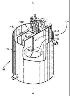
Referring now to Figure 2 of the drawings, a mixing
apparatus, according to a preferred embodiment of the
present invention and designated with general reference
numeral 100, is shown in use, in a manner fully described
in following paragraphs, with a vessel 102 having a
contiguous sidewall 104 centered about and defining a
longitudinal axis A-A.
CA 02444168 2003-10-10
WO 02/083280 PCT/CA02/00528
11
Full details of the preferred mixing apparatus of the
present invention will be set out in following paragraphs.
However, for greater clarity, it should firstly be
understood, generally, that the mixing apparatus 100
comprises a mixing head 106 having a head axis H-H
(illustrated in Figures 3, 7 and 8); mounting means for
mounting the mixing head 106 substantially coaxial to and
within the vessel 102 for longitudinal movement relative to
the head axis H-H, said mounting means being designated
with general reference numeral 108 in Figure 2; and
reciprocating means, designated with general reference
numeral 110, for effecting said longitudinal relative
movement of the mixing head 106 in a reciprocating manner.
The various parts of this preferred mixing apparatus will
now be described with more particularity.
With reference to Figure 7, the mixing head 106 will be
seen to include a blade portion 112, a hub member 114 and
a plurality of support webs 116.
The blade portion. 112, as shown, is constructed from six
arcuate segments 118. The segments 118 are arranged in
tubular relation so as to form a first tube end 120 and a
second tube end 122, illustrated in Figure 10, and are
secured, by bolts (not shown), to one another through
flanges 124 (see Figures 7, 8 and 9) provided at the ends
of each segment 118 for this purpose.
The tubular blade portion 112 defines and is centered about
the head. axis H-H, such that the first tube end 120 and the
second tube end 122 of the blade~portion 112 are spaced-
apart from one another therealong, and the blade portion
112 tapers in a substantially frustoconical manner from the
first tube end 120 to the second tube end 122.
CA 02444168 2004-02-11
12
The rate of taper is such that the angle a, defined by the angle
between the pair of axes X, X and Y, Y, which axes are .defined by
and coincident with the intersections of the outer surface 128
of the blade portion 112 and a plane P-P coincident with the
head axis, is greater than or equal to 90° and less than 180°
( 9 0 ° s a < 180 ° ) , as indicated in Figure 9 and Figure 10 .
The hub member 114 is also tubular, and is centrally disposed
adj acent to the blade portion 112 .
The plurality of, specifically, three, support webs 116
each extend between and connect the hub member 114 and the
blade portion 112. Such connection is effected by rivets
or bolts (not_shown).
With reference now to Figure 3, the preferred mounting
means 108 will be seen to comprise a mixer shaft 130 and a
linear bearing 132.
The mixer shaft 130 has a bottom end 134 operatively
rigidly connected to the mixing head 106 and extends from
said bottom end 134, substantially coincident with the head
axis H-H, to a top end 136 which is disposed above the
vessel 102 in use. Such rigid connection of the mixer
shaft 130 and the mixing head 106 may be effected by, for
example, threading the exterior of the bottom end of the
mixer shaft, and providing a corresponding thread on the
interior of the hub member (not shown).
The linear bearing 132 supports the mixer shaft 130 for
longitudinal movement; this is effected in the preferred
embodiment by mounting the bearing 132 to a housing 138
which is itself mounted, as illustrated in Figure 2, to a
frame 140 which, in the preferred embodiment shown, spans
over the vessel 102.
CA 02444168 2003-10-10
=Prmfied: 28 .11. 20U~; DES~PAiIItD . EP027240G2 1 F'CTCA 02 Q05
' 13
As best illustrated in Figure 4, the reciprocating means
110 comprises a shaft gripping means, designated with the
general reference numeral 142, for gripping the mixer shaft
130 adjacent its top end 136 and for effecting longitudinal
reciprocating movement of the shaft gripping means 142
through stroke length "S" with duration "T" for each cycle,
thereby to effect coincident longitudinal movement of the
mixing head 106 in said reciprocating manner through the
same stroke length "S", as indicated in Figure 3, wherein
the mixing head 106 is shown in blackline in a starting
position, and in phantom outline, at a position
longitudinally displaced from the starting position through
a distance "S" .
Such reciprocating movement is effected through a scotch
yoke apparatus 144, comprising a flywheel 146, a drive
means 148, a crank member 150 and a yoke 152, illustrated
in Figure 4 and in Figure 5.
The flywheel 146 is mounted to the housing 138 for rotation
about a rotational axis R-R (illustrated in Figure 4) which
is normal to the longitudinal axis A-A.
The drive means 148 is for driving rotation of the flywheel
146 and, in the preferred embodiment illustrated, comprises
an explosion-proof electric motor, operatively connected by
its drive shaft (not shown) to the flywheel 146.
The crank member 150 projects from the flywheel 146 in a
direction parallel to the rotational axis R-R and is
connected to the flywheel 146 for xotation therewith.
AMENDED SHEET ~1 ~ -~ ~ ~~00~
CA 02444168 2003-10-10
WO 02/083280 PCT/CA02/00528
14
The yoke 152 is displaced from the flywheel 146 in the
direction of the crank member 150 and has formed therein a
substantially linear race 154 which is in receipt of the
crank member 150 and is adapted to permit relative
translational movement of the crank member 150 and the yoke
152 as the flywheel 146 rotates.
The yoke 152 has threaded, coaxial bores 156 disposed on
its upper and lower surfaces to receive respective threaded
guide shaf is 15 8 . - Corresponding guide bearings 16 0 are
provided on the housing 138. When the yoke 152 is
operatively mounted with the guide shafts 158 disposed
within the guide bearings 160, the yoke 152 is positioned
with the race 154 arranged normal to the rotation axis R-R
and bisected thereby, and is mounted to the housing 138 in
a manner which constrains movement of yoke 152 otherwise
than along an axis B-B parallel to the.longitudinal axis A-
A and normal to the rotational axis R-R (best indicated in
Figure 4), such that during rota-tion of the flywheel 146,
the crank member 150 imparts longitudinal reciprocating
movement to the yoke 152, as indicated by the sequence of
Figures 6A-6D.
The length of the resultant stroke may be selected by
suitable adjustment to the radial position of the crank
member 150 (that is, the distance between the crank member
150 and the rotation axis R-R); for this reason, the crank
member 150 is threaded, and a plurality of threaded sockets
162 are provided in a radial array on the face of the
flywheel 146, as illustrated in Figure 5. The duration of
each stroke may be selected by suitable adjustment to the
rotational speed of the electric motor 148.
CA 02444168 2003-10-10
In the preferred embodiment, the yoke moves through a
stroke length "S", with a duration "T" for each cycle,
wherein 175 < 0.36 x ODZ/IDz x S/T < 250 when T is expressed
5 in minutes, S is expressed in inches, "ID" is an inside
blade diameter, expressed in inches and defined by the
outer surface 128 of the blade portion 112 and the second
tube end 122, and "OD" is an outside blade diameter,
expressed in inches and defined by the outer surface 128 of
10 the blade portion 112 and the first tube end 120, as
indicated in Figure 10.
Returning to Figures 4 and 5, the shaft gripping means 142
preferably comprises a clamp 163, specifically, a pair of
15 mating clamping blocks 164, each having a concave groove
166 of semi-circular cross-section formed therein to
grippingly receive the mixer shaft 130. Clamp 163 is
selectively rigidly affixed, by bolts 168, to the yoke 152,
such that longitudinal reciprocating movement is imparted
to the shaft gripping means 142 by said longitudinal
reciprocating movement of the yoke 152. This clamp
arrangement permits the relative depth of the mixing head
106 in the vessel 102 to be conveniently adjusted from
above; the clamp 162 need only be loosed, by disengaging
the associated bolts 168, whereupon mixer shaft 130 can be
raised or lowered as desired, and bolts 168 re-engaged.
The mixer shaft 130 is itself preferably constructed of a
plurality of tube segments 170, threaded at their ends and
joined to one-another in end-to-end relation by threaded
couplings 172, so that segments 170 can be added or removed
as desired, thereby to permit the aforementioned adjustment
feature to be more conveniently and fully exploited.
CA 02444168 2003-10-10
16
With general reference to Figure 4 and Figure 5, stresses
created on the yoke 152, by virtue of its carriage of the
shaft gripping means 142, are preferably countered by the
provision of a balancing shaft 174, rigidly connected to
the housing 138 to extend substantially parallel to
longitudinal axis A-A, and by a pair of mating linear
bearing blocks 176, each having a respective groove 178 of
semi-circular cross-section formed therein sheathed with a
self-lubricating material such as polytetrafluorethylene ,
which are mounted to the yoke 152 by bolts 180 and slidably
receive the balancing shaft 174 therethrough.
It has been found that the present invention can be used to
great advantage as a mixer for a vessel in a SXEW extractor
unit, as illustrated in Figures 2 and 3.
EXAMPLE 1
In the known application of the SXEW process previously
described, samples were taken from the outfall of each of
the primary vessel; secondary vessel; tertiary vessel and
settling tank of a respective secondary extraction unit (A)
and permitted to separate.
In a parallel secondary extraction unit (B) (ie processing
a pregnant leachate of substantially identical
composition), a mixing apparatus in accordance with the
present invention (OD=60; ID=40; a=120°; S=10; T=.0333,
driven by a 2hp motor) was substituted for the rotary mixer
in the secondary mixing vessel, and samples were again
taken from the outfall from each of the primary, second and
tertiary mixing vessels, and from the settling tank, and
permitted to separate.
CA 02444168 2003-10-10
17
Copper concentration (g/1) was measured in the organic
component of each sample, as follows:
(A) (B) [30cpm]
Cu(g/1) Cu (g/1)
Primary mixing vessel 2.01 2.01
Secondary mixing vessel 2.06 2.06
Tertiary mixing vessel 2.12 2.13
Settling tank 2.14 2.13
As would be expected, copper concentration from the primary
mixing vessel in each of the A and B lines is similar
(because to that point in the process, mixing is provided
by identical rotary mixers). However, unexpectedly, copper
concentrations in the outfall from the secondary mixers
also remained identical, and copper concentration in the
outfall from the settling tanks remained quite similar,
despite the almost 75o reduction in energy input (2 hp
drive motor for the reciprocating mixer, as compared to the
7.5 hp motor driving the rotary mixer).
CA 02444168 2003-10-10
18
Without intending to be bound by theory, it is believed the
mixing apparatus of the present invention provides mixing
currents which [at least in the context of the liquids
utilized in SXEW copper extraction, in a vessel having an
internal diameter D and a height H, wherein OD:D is between
about 1:2.5 to 1:4, OD: ID is greater than 1.0 and smaller
than or equal to about 1.5; and D:H is approximately 1:1]
create a dispersion characterized by consistent-sized
droplets, uniformly distributed throughout the mixing
vessel, whereas in a rotary mixer, there is a wide
variation in drop sizes, and in the distribution of said
drops, (perhaps due to the fact that the blade in a rotary
mixer moves at different speeds along its length) . This
uniform dispersion is believed to provide an environment
amenable to efficient mass transfer between phases, while
at the same time providing for substantial disengagement of
the mixed phases within a relatively short time frame.
Whereas the illustrations depict an embodiment of the
present invention which is preferred, various modifications
are contemplated.
For example, whereas in the preferred embodiment, a scotch
yoke apparatus is utilized to provide a linear
reciprocating movement, it will be evident that other
mechanisms, such as crank shafts, cam and cam follower
mechanisms, and swash plates are possible substituents
therefor.
CA 02444168 2003-10-10
WO 02/083280 PCT/CA02/00528
19
It should also be noted that, while in .the preferred
embodiment illustrated, the head axis H-H and the
longitudinal axis A-A are coincident, this need not be the
case. '
As well, whereas in the preferred embodiment illustrated,
the mixing head tapers uniformly along its length, so as to
take on a substantially frustoconical shape, and the
mounting means is adapted to mount the mixing head to the
vessel with the first tube end disposed above the second
tube end, it is possible for the mixing head to assume non-
frustoconical form, wherein the rates of taper differ at
the top and bottom ends, and also for the mixing head to be
disposed with the second tube end disposed above the first
tube end, as illustrated in Figure 16. Flow baffles 184
can also be disposed within the vessel, as indicated also
in Figure 16.
Additionally, whereas the preferred blade portion and
support webs are substantially smooth, it is contemplated
that the blade portion 112 can be formed with a plurality
of perforations 186 each extending between the inner
surface 126 and the outer surface 128, as illustrated in
Figure 12, and that the support webs 116 may be provided
with a plurality of perforations 188, as well as a
plurality of tabs 190 each substantially overlying a
respective perforation 188 and being connected to the
support web 116 at one edge of said respective perforation
188 .to form a gill, as illustrated in Figure 11. In this
manner, the characteristics of the mixing currents produced
by the blade portion in motion can be finely tuned to
control the droplet size of the dispersion, and hence, the
mixing efficiency of the device, which feature is not
available in prior art mixers.
CA 02444168 2003-10-10
WO 02/083280 PCT/CA02/00528
As a further alternative, illustrated in Figure 13, the
blade portion 112 may be provided with,a plurality of
dimples 192 projecting outwardly from the outer surface 128
and inwardly from the inner surface 126. Similarly, this
5 allows fine tuning of the mixing device of the present
invention in a manner not taught by the prior art.
For the purpose of minimizing friction, the preferred crank
member 150 is of two-part construction, including an inner
10 axle portion 182 which is fixedly connected to the flywheel
156 and an outer roller portion 184 which is rotatably
mounted by bearings (not shown) on the axle portion 182
(best illustrated in Figure 5).. However, this is not
necessary.
Of course, whereas the detailed description herein pertains
specifically to the recovery of copper from copper bearing
ores, it 'should also be, understood that the present
invention may be utilized in other applicat~.ons wherein
SXEW processes are utilized, such as, for example, in the
recovery of zinc, nickel, platinum and molybdenum.
Moreover, it will be evident that the invention may have
advantageous utility even outside the SXEW process, in
other mixing applications, such as in the context of a
froth flotation cell, illustrated in Figures 14 and 15,
wherein the mixing apparatus is used to agitate a slurry to
form a froth, and a paddle mechanism 32 is operatively
mounted to the vessel 102 to scour froths produced thereby.
It will, of course, also be understood that various other
modifications and alterations may be used in the design and
manufacture of the mixing apparatus according to the
present invention without departing from its spirit and
scope. Accordingly, the scope of the present invention
should be understood as limited only by the accompanying
claims, purposively construed.