Note: Descriptions are shown in the official language in which they were submitted.
CA 02444213 2003-10-09
DEVICE FOR DISTRACTING VERTEBRAE AND DELIVERING A
FLOWABLE MATERIAL INTO A DISC SPACE
FIELD OF THE INVENTION
This invention relates generally to a device for intervertebral disc
augmentation,
more particularly to a device for distracting vertebral bodies and
simultaneously injecting
a flowable material into the disc space for augmentation after perfonming a
discectomy or
nucleotomy.
BACKGROUND OF TIIrEE INVENTION
Spine fusion procedures represent the state of the art treatment for
intervertebral
disc problems, which generally involve open surgery and the use of interbody
fusion
cages and spinal fixation systems to stabilize the fusion site: An alternative
treatment
under evaluation is to replace the disc or nucleus pulposus with a prosthetic
device.
Examples of some devices currently under investigation include in-situ cured
polymers
such as polyurethanes and protein polymers, which may have properties varying
from a
rubbery hydrogel to a rigid plastic. Problems associated with these devices
occur during
insertion, whereby the pressure required to fill the disc space can cause
leakage of the
material into sensitive adjacent areas.
A number of devices are available for distracting vertebral bodies or for
injecting
material into the disc. Some devices are capable of both distraction and
injection using
the same instrument. These types of devices use a deflated balloon attached to
a cannula
and inserted between the vertebral bodies. The balloon is inflated with a
prosthetic fluid
througb the cannula to distract the vertebral bodies. This requires high-
pressure delivery
of the fluid to achieve the pressure needed to distract the vertebral bodies
and the balloon
and fluid permanently remain in the disc space. Alternatively, a separate
device is used
CA 02444213 2003-10-09
to inject the prosthetic fluid around the balloon and the balloon is used
strictly for
distraction after which it is deflated and removed,
US patent 4,772,287 ("Ray I") discloses a bladder injected with thixotropic
gel
implanted between two vertebral bodies to restore the disc height. The
technique
described requires that the vertebral bodies arc first distracted and a bore
drilled to allow
for insertion of the bladder.
US patent 5,562,736 ("Ray II") discloses a method for implanting a prosthetic
to disc nucleus. Ray Il teaches cutting a fi=st and second flap in the
annulus. The flaps
provide access to the nucleus, Ray II then teaches using an inflatable jack to
distract the
disc space prior to insertion of the prosthetic spinal disc nucleus. The jack
has a deflated
balloon on its end that is inserted into the nucleus through one' of the
flaps. The balloon
is inflated with fluid causing the vertebral bodies to distract. Once the
vertebral bodies
arc sufficiently distracted the fluid flow is stopped and the prosthetic
spinal disc nucleus
is inserted through the. other flap, The balloon is then deflated and the
second prosthetic
spinal disc nucleus is inserted. The flaps are closed and placed in contact
with the
annulus by a suture, staple or glue.
zo U.S. Patent 6,187,048 (" Milner") discloses an implant for an
intervertebral disc
nucleus pulposus prosthesis made from a conformable, in-situ curable, material
which is
resiliently deformable. Milner teaches removing the nucleus material, then
either
injecting through the annulus or creating an openirng in the annulus to
deliver a curable .
material under pressure into the nucleus space. The pressure is necessary to
ensure
conformation to the nucleus space and/or to increase the internal pressure of
the disc
space to distract the vertebral bodies. The amount of pressure needed to
distract the, disc
space is high and may allow the material to flow through cracks or voids in
the antsulus
into the disc space. Milner also describes an embodiment where the curable
material is
injected into a flexible container that is inserted first into the nucleus
space in a deflated
state and inflated by the material as the material is injected. This method
relies on th~e-
pressure of the fluid as it is injected to distract the vertebral bodies.
Although this avoids
2
CA 02444213 2003-10-09
the problem of the material leaking through the annulus, it imposes certain
constraints
such as a designing a cover of the correct shape and size suitable for safe
injection of the
curable material and prevention of leakage of the material from the cover once
filled.
s ~ U.S Patent 6,248,131 ("Felt's describes distracting and injecting at the
same time
using a balloon device. The balloon can be used as a shell for containing the
injected
curable biomaterial and also used as a distraction means as the material is
injected,
Another embodiment describes the balloon as a cylinder shape which when
inflated
inside the disc space bears against the endplates for the vertebral bodies $nd
distracts
them. Then a second device is used to inject the curable biomaterial amend the
balloon
cylinder.' The material is allowed to cure and then the balloon is removed-and
a seeond~
curable biomaterial can be injected into the space left where the balloon was.
In sum,
when Felt discloses injecting material outside of the balloon, Felt discloses
using a
second device to carry out the injection. Insertion of this second device into
the disc
is should typically require a second breach of the annulus fibrosis.
. 'Therefore; in general, in some embodiments, the art describes free
injection' of
material which may lead to uncontrolled leakage. The art also describes
injection of the
material into a deflated balloon, which requires leaving the balloon inside
the disc space.
2o Lastly, the art describes same of the problems associated with some of
these methods
include the need for a first instrument to distract the disc space and another
to insert or
inject the prosthetic fluid, Also, when two devices are used, two incisions in
the annulus
are required so that distraction and insertion can be accomplished. As noted
above, some
methods require insertion under high - pressure, thereby creating a potential
for the
z5 prosthetic fluid to oozc or seep out of the disc space infra-operatively.
SUMMARY OF THE INVENTION
Tbie present inventors have developed a device that can be used after
performing a
3o discectomy or nucleotomy to both distract the disc space and inject
material into the disc
space without subjecting the injected material to compressive forces. Because
this device
3
CA 02444213 2003-10-09
provides for the distraction of the vertebral bodies through a means separate
from the
means for injxting the material, it not only provides a way of delivering a
flowable ,
material into the disc space under low pressure, but also allows for the
material to cure
in-situ without any compressive forces acting upon it. After injection, the
device can be
removed from the disc space, thereby substantially restoring the nucleus to
its original
configuration and shape, as well as restoring natural spinal alignment (i.e.,
natural
lordosis or lcyphosis).
Therefore, in accordance with the present invention, there is provided a
device for
to distracting two adjacent vertebral bodies defining a disc space
therebetween and
delivering a flowable material into the disc space, comprising: - . ~ . . .
a)a body comprising:
i)a proximal portion,
is ii)e distal portion comprising a shape adapted to distract the disc space,
and
iii)a first longitudinal bore extending through the body and defuzing a first
outlet
in the distal portion opening onto the disc space.
Also in accordance with the present invention, , there is provided a device
for
a0 distracting two adjacent vertebral bodies defining a disc space
therebetween and
delivering a flowable material into the disc space, comprising:
a) means for distracting the disc space, and
b) means for delivering a fyowable material into the disc space.
Also in accordance with the present invention, there is provided a method for
distracting two vertebral bodies and delivering a flowable material into an
intervertebral
disc space having an outer annulus, comprising the steps of .
a) providing a device for distracting and delivering a flowable material
- 3.o comprising, .a body having a , proximal portion and a distal portion,
the '
distal portion having a shape adapted to distract, the body also having a
4
t
CA 02444213 2003-10-09
longitudinal bore defining a fast outlet port in the distal portion, and a
first
injection port in the proximal portion;
b) inserting the distal portion of the device through the outer annulus;
c) distracting.the vertebral bodies with the shape; and . .
d) introducing the flowable material into the disc space through the injection
port.
BRIEF DESCIltIIPTION OF THE DRAWINGS
These and other features of the invention wall be understood from the
description
below, takeia together with the Figures which show illustrative err~badiments -
and several -
variations and details of construction thereof, wherein:
FIG.1 shows a top view of the device of the present invention inserted into a
disc space.
FIG.2 shows a top view of the device of FIG.I inserted into a disc space after
rotating the
device 90 degrees ~to distract the disc space.
FIG.3 shows a top view of an injection of a flowable material into the disc
space by the
zo device of FIG.I .
FIG.4 shows the withdraw) of the device from the disc space aRer injection of
flowable
raateriaJ into .the disc space.
as
FIG. 5 shows a distal portion of another embodiment of the device of the
present
invention having an opening at the distal end of the shape adapted for
distraction.
DETAILED DESCRI1PT10N OF THE INVENTION
5
CA 02444213 2003-10-09
For the purposes of the present invention, the "proximal portion" of the body
is
that portion that penetrates the annulus fibrosis, while the "distal portion"
of the body is
that portion that remains outside the annulus fibrosis.
The present invention provides a device for distracting (and preferably
aligning)
two vertebral bodies and delivering a flowable material into the disc space,
af3er a
discectomy or nueleotomy has been performed. The present invention simplifies
and
combines the conventional separate methods of distracting two vertebral bodies
and
delivering a fiowable material into the disc space formed after the removal of
the nucleus
in a uay that allows for the distraction (and preferably spinal alignment) and
delivery to
be performed by a single device under lvw pressure. ' -
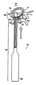
Now referring to FIGS. 1-2, in preferred embodiments. of the invention, there
is
provided a device 10 for distracting two vertebral bodies and delivering a
flowable
is material into a disc space comprising: . .
a) a body 30 comprising:
r) a proximal portion 15,
ii) a distal portion 32 comprising a shape 17 adapted to distract the disc
20 space,and .
iii) a first longitudinal bore 37 extending through the body and definirig'a
first outlet 34 in the distal portion opening onto the disc and a fret
injection port 44.
The device of Figures 1-2 further comprises a radially extending flange or
stop 50
disposed at the distal most section of the proximal portion of the body.
The shape 17. adapted to distract has a width W is sufficiently large so that,
upon
~0 rotation, it can sui~iciently distract the disc space.
6
CA 02444213 2003-10-09
The device of Figures 1-2 further comprises a second longitudinal bore 57
extending through the body and defining a second outlet 54 in the distal
portion opening
onto the disc and a second injection port 45.
The devices of Figures 1-2 further comprises first and second tubes 61 and 63,
each tube having a proximal open end 42, 43 and a distal open end. In this
Figure, each
tube runs parallel to the longitudinal axis of the body and enters their
respective
injection ports 44,45 of the proximal portion of the body, and terminates
within the body
at their respective outlets 34;35. The injection ports accommodate insertion
of the tubes
such that when flowable material is injected into the proximal open ends of
the tubes, it
exits through the distal end of the tube and flows into the disc space through
the fret
outlet on the distal portioa of the body.
The device of the present invention is typically used immediately after a
z5 discectomy or a nucleotomy.'In performing the discectomy or a nucleotvmy,
the surgeon
typicahy makes a small (~ 5mrn) hole in the annulus fibrosis through which the
nucleus
pulposus is removed.
In one preferred method of this invention, the surgeon preferably makes a
device
20 entry hole in the annulus fibrosis. The device entry hole is typically made
by either i)
making a second hole in the annulus fibrosis larger than the bolt through
which the
nucleotomy is performed, or ii) enlargening the hole through which the
nucleotomy is
performed,
zs Next, the surgeon advances the distal end of the device through an incision
in the
annulus in a first orientation as shown in F1G. 1 until stepped by the stop.
Next, now
referring to FIG. 2, the surgeon rotates the device 90 °C (as shown by
the curved arrow)
to a second orientation whereby the desired distraction of the vertebral
bodies is
achieved. Now referring to FIG. 3, with a syringe 101 attached to injection
port 43 by its
3o port 103, the surgeon then delivers through the injection port 44 a
flowable material that
passes through the body and exits out the outlet port 35 into the disc space.
The surgeon
7
CA 02444213 2003-10-09
allows the material to begin to cure within the disc space .to a point where
the at feast
partially cured material can withstand the compressive forces of the spine
viithout leaking
into the spinal canal. At this time, and now referring to FIG. 4, the surgeon
then removes
the device from the patient.
3
In some embodiments, the distraction and injection are carried out as
described
above, and then a specified time period is elapsed before the device is
withdrawn. This
pause allows the injected material to partially cure. 3'tte partially cured
material is
advantageous because it is less susceptible to leak from the annulus fibrosis
during
' 10 withdrawl of the device. .
In some embodiments; the withdrawl of the device is a gradual withdraw,
wherein
flowable material is slowly injected into the void distal of the distal port
created by the
withdr$wl. This gradual withdrawlinjection procedure is advantageous because
it allows
~5 the swgeon to fill the entire disc space with flowable material. In these
embodiments, it is
advantageous to use a device in which the outlets are as distal as possible in
order to
allow the surgeon to continur~filling up to the point of withdrawl.
In one preferred use, a first substantially horizontal incision is made in the
20 annulus, 'the device is inserted into the disc space and rotated, the
flowable material is
injected into the disc space, a substantially vertical incision Prefe~bly
orthogonal to and
bisecting the $rst horizontal incision) is made in the annulus, and the device
in its rotated
orientation is withdrawn through the substantially vertical incision.
z3 The body of the device of the present invention may have any shape that
accommodates a distal portion: shaped for distracting and injecting.
In ,another embodiment of the present invention; the device is integral. In
prefen:ed embodiments thereof, the body component of the device is hollow and
forms
30 . the Jongitudinal .bore, is substantially cylindricaIly~shaped, and has an
injection port
8
CA 02444213 2003-10-09
within proximal portion for injecting a flowable material and an outlet :port
within its
distal portion from wl9ich the flowable material exits into the disc space.
More preferably, the body has a length L and a radius R, wherein the length L
is
at least ten times the radius R. In these embodiments, the long length of the
body shows
the surgeon to easily insert the distal portion of the body into the disc
space while
keeping the proximal end thereof outside the body. Thus, these embodiments are
particularly useful in minimally invasive surgeries requiring access thmugh
very small
incisi ons.
The device may further comprise a stop mechanisrh SO disposed at the distal
end
of the proximal portion for preventing the body of the device from entering
too far into
the disc space. The stop mechanism may include a flange extending radially
from the
body. This stop mechanism allows the surgeon to place the distal portion
accurately prior
~ s to injecting the flowable material.
The distal portion of the body includes the shape that, is adapted to distract
the
adjacent vertebral bodies and restore spinal alignment.
no In some embodiments, the shape adapted to distract is adapted to distract
upon
insertion into the disc space. Preferably, this shape includes a tapered
portion having a
rnaxim~rn height substantially equal to the desired distraction height and a
distally
decreasing height that allows for easier insertion between the vertebral
bodies. Once
inserted, the device can be advanced until the desired amount of distraction
is reached.
z5 In some preferred embodiments, the body has a cylindrical proximal portion,
and the
distal portion has a symmetric taper (preferably, a bullet).
In another embodiment, the shape adapted to distract is a spreader. In some
spreader embodiments, the body has a rectangular cross-section, preferably
with rounded
30 outer edges. The distal portion has a height less than the disc space and a
width about
eslual to that of a distracted disc space. In use, the distal portion can be
inserted between
9
CA 02444213 2003-10-09
the vertebral bodies so that tht lesser height dimension spans a portion of
the disc space,
and then rotated 90 degrees so that the bearing surfaces 7I,72 on either side
of the greater
width dimension bear against the opposing endplates and distract the disc
space,to
accomplish the necessary amount of distraction.
Ia some embodiments, the distal portion may be removable from the body. In
these embodiments the surgeon leaves the distal pardon in the disc space as a
spacer and
injects a flowable material (like bone cement) around and through the distal
portion to
secure its position within the disc space. .
l0
In some embodiments, the shape adapted to distract has at least one
bearing surface bavin~ a convex shape adapted to match the contour of the
vertebral
endplate.
In some embodiments, the shape adapted to distract has a leading edge that is
curved to prevent fracture of ahe endplate.
In some embodiments, the distractor is shaped to provide. an anterior-
posterior
angle to the distracted disc space. In these embodiments, the shape adapted to
distract has
an upper bearing surface sand a lower bearing surface, wherein the upper .and
lower
surfaces define a non-zero angle. .In some embodiments, the distal portion of
the shape is
greater than the proximal portion, and produces a non-zero angle of between
about 5 and
about I5 degrees. This angle provides Iordosis when inserted posteriorly, and
kyphosis
when inserted aateriorly. In some embodiments, the proximal portion of the
shape is
greater than the distal potion and produces a non=zero angle of between about -
5 and
about -15 degr8es. This angle provides kyphosis when inserted posteriorly and
Iordosis
when inserted anteriorly.
Now referring to FIG. 5, in some embodiments, the distal portion has an upper
fin
X81 extending therefrom, the fin comprising an upper bearing surface 9I having
a convex
shape. More preferably, the distal portion also has a lower fin 82 extending
therefrom, the
to
CA 02444213 2003-10-09
Lower fin comprising lower bearing surface 92 which also has a convex shape,
thereby
producing a football shaped distal portion. This embodiment is useful when the
device is
inserted laterally, as the convexity corresponds to the natural contour of the
opposing
endplates.
In other embodiments, the leading and trailing edges of the fins of FIG. 5 are
. tapered to faciliate insertion and removal from the disc space.
In sorac embodiments, the shape adpated to distract is a balloon used purely
for
distraction purposes (i.e, fluid is injected into the disc space through an
opening not
' associated with the balloon) . In preferred embodiments thereof, the body
comprises: . ~ ._ _
a) an inflatable balloon having art injection port , .
b) a first tttroughbore having a distal portion in fluid connection with the
ballrxin
injection port, and
t5 . c) a second throughbore having a distal portion opening into the disc
space.
In preferred uses thereof, the surgeon inserts the distal portion of the body
into the
disc space, passes a first fluid through the first thmughbore to inflate the
balloon acid
thereby distract the disc space, a:sd passes a second fluid through the seoond
throughbore
so that the second fluid enters the distracted disc space undor low pressure.
In some embodiments, the shape adapted to distract includes upper and Lower
jaws mounted on a pivot. In use, the shape adapted to distract enters the disc
space in a
closed position: Then, the surgeon activates the device so that the upper and
lower jaws'
2s separate from each other to an open position. The outer swfaces of each jaw
press against
the opposing endplates to provide the desired distraction.
The injection port includes an opening located along the proximal portion of
the
surface of the body.. The flowable material can be' injected through this port
into the
body. There may be more than one injection port located along the proximal
portion of
the body. , The port can include a connection means to an injection device. _
The material
~t
CA 02444213 2003-10-09
can be injected into the port through any means including syringe and a pump.
Preferably, the injection means is a syringe. Ia some embodiments, the
iqjeciion means
comprises two syringes.
s The outlet port includes an opening located on the distal portion of the
surface of
the body. It allows the flowable material to exit the body and enter into the
disc space.
In some embodiments, there may be more than one outlet port on the distal
portion. The
outlet port may be located at the distal end of the body or anywhere along the
distal
portion of the body.
- ' In some embodiments, as in FIG. 1, the dewicc comprises two distal_autlet
ports.
Preferably, each outlet port opens onto the disc space through a non-bearing
surface of
the distal portion of the device. This allows the surgeon to fill each side of
the disc space
when the distractor is in place.
IS
Generally, the more distally disposed the outlet port, the longer the surgeon
can
continue filiing the disc space as the distractor is withdrawn from the disc
space. In some
embodiments,- the device comprises a outlet port opening onto the disc space
from the
distal half of the distractor component, preferably the distal most quarter of
the disc
2o space. Now referring to FIG.'S, the device comprises a outlet pori 20
opening onto the
disc space from the distal end of the distractor component. This embodiment
allows the
swgeon to continue filling the disc space until the distractor component is
essentially .
. removed from the disc space. The device of FIG. 5 further comprises a outlet
port. 24
opening onto the disc space from a non-bearing surface 22 within the distal
end of the
2s distractor component. A second outlet port (not shown) may be provided
opposite of
outlet port 24.
The device may be made of materials typically selected for use in surgical
instruments. Preferably, the entire device is sterile.
12
CA 02444213 2003-10-09
When placed in-situ (and in some instances, after curing, the flowable
material
preferably replaces as least a portion of the natural function of the nucleus
fibrosis.
Accordingly, in preferred embodiments, the flowablc material is a nucleus
pulposus
replacement. The flowable materials are preferably selected from the ,group
conistsing of
liquids, gels (such as bydmgels, such as PVA~based hydrogels), and solid
materials that
are sufficiently morseliud to flow under pressure. Typically, the liquid
flowable material
cures in situ. The flowable material may cwe in-situ to create a stiff
material (suoh as
polyurethane), of a relatively pliant material (such as silicone).
Therefore, in accordance with the present invention, there is provided a Idt
for
providing a nucleus pulposus replacement matirrial, composing: - - - -
a) device for distracting two adjacent vertebral bodies defvning a disc space
therebetween and delivering a flowable material into the disc space comprising
a
Z 5 body comprising:
i) a proximal portion,
ii) a distal portion comprising a shape adapted to distract the disc space,
and
. iii) a longitudinal bore extending through the body and defining a first
outlet in the distal portion opening onto the disc space, and
b) a flowable material suitable for use as a nucleus pulposus replacement
material.
The present invention relates to a surgical device for distracting two
vertebral
' bodies and delivering a flowable material into the disc space. The invention
being thus
disclosed and illustrative. embodime~ots depicted herein, further variations
and
modifications of the invention, will occur to those skilled in the art, and
a11. such
variations and modifcatione are considered to be within the scope of the
invention, as
defined by. the claims appended hereto and equivalents thereof.
13