Note: Descriptions are shown in the official language in which they were submitted.
CA 02444246 2009-07-30
SPECIFICATION
TITLE OF THE INVENTION
FUEL CELL AND METHOD OF MANUFACTURING THE FUEL CELL
TECHNICAL FIELD
The present invention relates to a fuel cell and
a manufacturing method of the same.
BACKGROUND ART
In conventional, as shown in Fig. 21, there has
been known a fuel cell in which an electrolyte membrane
51, catalyst electrodes 52 and 53, gas diffusion layers
54 and 55, separators 56 and 57 and gaskets 58 and 59
are assembled in an illustrated manner. In these
constituting parts, the electrolyte membrane 51
constitutes a membrane electrode complex (also called
as a reaction electrode portion or an MEA) together
with the catalyst electrodes 52 and 53 arranged on both
surfaces thereof, and the membrane electrode complex
60 constitutes a UEA 61 together with the gas diffusion
layers 54 and 55 arranged on both surfaces thereof.
Further, as shown in Fig. 22, a gas communication groove
62 is provided in the separators 56 and 57 in a
predetermined plan layout, and a spacer 63 is arranged
in this portion in place of the gasket 58 or 59. With
respect to the other portions, the gaskets 58 and 59
1
CA 02444246 2003-10-09
fixed to the separators 56 and 57 clamp the electrolyte
membrane 51 between them so as to secure a sealing
property.
However, in accordance with this prior art, since
the gaskets 58 and 59 fixed to the separators 56 and
57 clamp the electrolyte membrane 51 between them,
whereby the sealing property is secured as mentioned
above, there is a disadvantage that the electrolyte
membrane 51 tends to be broken near the gaskets 58 and
59. The electrolyte membrane 51 tends to be affected
by dry and wet due to operation and stop of the cell,
and there is a risk that the electrolyte membrane 51
is broken in a short time period due to a great stress
caused by compression and expansion of the membrane.
Further, in accordance with the prior art mentioned
above, since the spacer 63 having a high rigidity must
be independently arranged in the portion of the gas
communication groove 62, an assembling step for the
cell is complex, and thus a contact state with the
electrolyte membrane 51 is different from the other
portions, so that the structure is made such that the
electrolyte membrane 51 tends to be broken.
Further, in accordance with the prior art
mentioned above, since the constituting parts are
sequentially assembled at a time of assembling the cell,
there is a disadvantage that the assembling step is
2
CA 02444246 2003-10-09
complex in view of this point. That is, as described
above, the fuel cell has the separator constituted by
the carbon plate or the like, the membrane electrode
complex for reacting the gas, the gas diffusion layer
made of a carbon fiber or the like for promoting a gas
diffusion, and the gasket made of a rubber elastic
material or the like for sealing the gas and a
refrigerant, as the main constituting parts, however,
since these constituting parts have been
conventionally assembled sequentially at a time of
assembling the fuel cell, a lot of labor and time are
required for this assembly. On the other hand, in
recent years, there has been invented an integral
product of the separator and the gasket in which the
gasket is integrally formed directly on the carbon plate,
(refer to Japanese Unexamined Patent Publication No.
2000-133288) , however, it is impossible to avoid the
structure in which the spacer 63 having a high rigidity
is independently arranged in the portion of the gas
communication groove 62, so that the cell assembling
step becomes complex, and it is hard to carry out an
automation for the purpose of reducing the
manufacturing cost, in a stacking step of alternately
stacking the separator and the UEA.
The gas diffusion layer is made of a sintered body ,
a woven fabric or a non-woven fabric of a fiber-like
3
CA 02444246 2003-10-09
material such as a carbon fiber, a metal fiber, an
inorganic fiber or the like, and is a porous body having
a continuous gas permeability since a gas permeability
is required. Accordingly, a rigidity and a strength
are lower than a dense structure body, the gas diffusion
layer tends to be collapsed due to an excessive
pressurization so as to be permanently deformed, and
a handling property is not good in view of an assembling
work. Accordingly, shapes of the gaskets are not
uniformed due to a breakage, a collapse or a deformation
of the gas diffusion layer caused by pressurizing for
positioning or integrating at a time of forming the
gasket or assembling with the membrane electrode
complex, the separator or the like after forming the
gasket, so that there is fear that a surface pressure
required for sealing with respect to an opposing surface
to the gasket is short or excessive. Further, since
the gas diffusion layer has the porous structure, there
is fear that a gas is leaked in a layer direction of
the gas diffusion layer.
The present invention is made by taking the above
matter into consideration, and an object of the present
invention is to provide a fuel cell and a manufacturing
method of the same which can effectively prevent an
electrolyte membrane from being broken, can make an
assembling step for the fuel cell easy, and can achieve
4
CA 02444246 2003-10-09
an excellent sealing property.
In this case, the present invention can be also
applied to a fuel cell which directly use a liquid
fuel such as a methanol or the like (a direct methanol
fuel cell), in addition to a fuel cell which uses a
gas fuel such as a hydrogen or the like.
DISCLOSURE OF THE INVENTION
In order to achieve the object mentioned above,
in accordance with a first aspect of the present
invention, there is provided a fuel cell comprising:
a membrane electrode complex in which catalyst
layers are respectively arranged on both surfaces of
a electrolyte membrane;
first and second gas diffusion layers which are
arranged on both surfaces of the electrode complex;
separators for respectively supplying reaction
gas to the first and second gas diffusion layers; and
a gasket for sealing the reaction gas,
wherein the gasket is formed on a surface of the
gas diffusion layer so as to oppose to the separator,
at least the gasket forming portion of the gas diffusion
layer has a lower void content than the portion which
is in contact with the catalyst layer, and the gasket
arranged in the first and second gas diffusion layers
is integrally formed at least via a through hole passing
through both the first and second gas diffusion layers.
CA 02444246 2003-10-09
Further, in accordance with a second aspect of
the present invention, there is provided a fuel cell
comprising:
a membrane electrode complex in which catalyst
layers are respectively arranged on both surfaces of
a electrolyte membrane;
first and second gas diffusion layers which are
arranged on both surfaces of the electrode complex;
separators for respectively supplying reaction
gas to the first and second gas diffusion layers; and
a gasket for sealing the reaction gas,
wherein the gasket is formed on a surface of the
gas diffusion layer so as to oppose to the separator,
at least the gasket forming portion of the gas diffusion
layer has a lower void content than the portion which
is in contact with the catalyst layer, and the gasket
arranged in the first and second gas diffusion layers
is connected to an insulating spacer provided on a back
surface of the gas diffusion layers via a through hole
provided in each of the gas diffusion layers.
Further, in accordance with a third aspect of the
present invention, there is provided a fuel cell
comprising:
a membrane electrode complex in which catalyst
layers are respectively arranged on both surfaces of
a electrolyte membrane;
6
CA 02444246 2003-10-09
first and second gas diffusion layers which are
arranged on both surfaces of the electrode complex;
separators for respectively supplying reaction
gas to the first and second gas diffusion layers; and
a gasket for sealing the reaction gas,
wherein the gasket is. formed on a surface of the
gas diffusion layer so as to oppose to the separator,
at least the gasket forming portion of the gas diffusion
layer has a lower void content than the portion which
is in contact with the catalyst layer, and the gasket
arranged in the first and second gas diffusion layers
is integrally formed so as to cover at least end portions
of the first and second gas diffusion layers.
Further, in accordance with a fourth aspect of
the present invention, there is provided a fuel cell
comprising:
a membrane electrode complex in which catalyst
layers are respectively arranged on both surfaces of
a electrolyte membrane;
first and second gas diffusion layers which are
arranged on both surfaces of the electrode complex;
separators for respectively supplying reaction
gas to the first and second gas diffusion layers; and
a gasket for sealing the reaction gas,
wherein the gasket is formed on a surface of the
gas diffusion layer so as to oppose to the separator,
7
CA 02444246 2003-10-09
at least the gasket forming portion of the gas diffusion
layer has a reduced void content in comparison with
the portion which is in contact with the catalyst layer.
Further, in accordance with a fifth aspect of the
present invention, there is provided a method of
manufacturing a fuel cell gasket as recited in the third
aspect or the fourth aspect mentioned above, wherein
an adhesive agent is applied to the gasket forming
portion having the lower void content in the gas
diffusion layer, and the gasket formed in a
predetermined shape is bonded thereon.
Further, in accordance with a sixth aspect of the
present invention, there is provided a method of
manufacturing a fuel cell gasket as recited in the third
aspect or the fourth aspect mentioned above, wherein
an adhesive agent is applied to the gasket forming
portion having the lower void content in the gas
diffusion layer, and the gasket is formed thereon in
accordance with any one of an injection molding method,
a print method, a dispenser method, a spray method and
a compression molding method.
Further, in accordance with a seventh aspect of
the present invention, there is provided a method of
manufacturing a fuel cell gasket as recited in the third
aspect or the fourth aspect mentioned above, wherein
the gasket is formed in the gasket forming portion having
8
CA 02444246 2003-10-09
the lower void content in the gas diffusion layer in
accordance with any one of an injection molding method,
a print method, a dispenser method, a spray method and
a compression molding method by using an adhesive rubber
as a material.
Further, in accordance with an eighth aspect of
the present invention, there is provided a method of
manufacturing a fuel cell gasket as recited in the third
aspect or the fourth aspect mentioned above, wherein
a surface roughness is secured in the gasket forming
portion having the lower void content in the gas
diffusion layer, and the gasket is formed thereon in
accordance with any one of an injection molding method,
a print method, a dispenser method, a spray method and
a compression molding method.
Further, in accordance with a ninth aspect of the
present invention, there is provided a fuel cell as
recited in any one of the first 'aspect to the fourth
aspect mentioned above, wherein the void content of
the gasket forming portion is reduced by impregnating
any one of rubber, resin, carbon and an inorganic
material in the gasket forming portion of the gas
diffusion layer.
Further, in accordance with a tenth aspect of the
present invention, there is provided a fuel cell as
recited in any one of the first aspect to the fourth
9
CA 02444246 2003-10-09
aspect mentioned above, wherein a bulk density is made
high in the gasket forming portion of the gas diffusion
layer, and the void content is reduced in the gasket
forming portion of the gas diffusion layer.
Further, in accordance with an eleventh aspect
of the present invention, there is provided a fuel cell
as recited in any one of the first aspect to the fourth
aspect mentioned above, wherein a gasket made of a
rubber-like elastic material is formed after
previously impregnating any one of rubber, resin,
carbon and an inorganic material in the gasket forming
portion of the gas diffusion layer, and bonding a
membrane electrode complex to the first and second gas
diffusion layers.
Further, in accordance with a twelfth aspect of
the present invention, there is provided a gas diffusion
layer for a fuel cell, the gas diffusion layer being
=used in the fuel cell as recited in any one of the first
aspect to the fourth aspect mentioned above, wherein
rubber or resin is impregnated in the gasket forming
portion of the gas diffusion layer, and an insulating
spacer made of rubber or resin is formed on one surface
of the impregnation portion.
Further, in accordance with a thirteenth aspect
of the present invention, there is provided a gas
diffusion layer for a fuel cell, the gas diffusion layer
CA 02444246 2003-10-09
being used in the fuel cell as recited in any one of
the first aspect to the fourth aspect mentioned above,
wherein rubber or resin is impregnated in the gasket
forming portion of the gas diffusion layer, and a gasket
made of a rubber-like elastic material is formed at
least in the gasket forming portion of the gas diffusion
layer.
Further, in accordance with a fourteenth aspect
of the present invention, there is provided a method
of manufacturing a gasket of a fuel cell recited in
any one of the first aspect to the fourth aspect
mentioned above, comprising the steps of:
arranging and bonding first and second gas
diffusion, layers on both surfaces of a membrane
electrode complex in which catalyst layers are
respectively arranged at least on both surfaces of a
electrolyte membrane; and
thereafter forming a gasket on the gasket
diffusion layer surface facing to a separator by
rubber or resin and simultaneously carrying out an
impregnation process in the gasket forming portion of
the gas diffusion layer.
Further, in accordance with a fifteenth aspect
of the present invention, there is provided a fuel cell
as recited in any one of the first aspect to the fourth
aspect mentioned above, wherein the gaskets are
11
CA 02444246 2003-10-09
provided at corresponding positions with respect to
the membrane electrode complex, in portions in which
the gaskets are formed on the surfaces of-the first
and second gas diffusion layers so as to face to the
separator.
Further, in accordance with a sixteenth aspect
of the present invention, there is provided a fuel cell
as recited in any one of the first aspect to the fourth
aspect mentioned above, wherein a groove which receives
at least the gasket is formed in the separator, the
groove is shallower than the height of the gasket, and
a cross sectional area thereof is larger than a cross
sectional area of the gasket.
Further, in accordance with a seventeenth aspect
of the present invention, there is provided a fuel cell
as recited in any one of the first aspect to the fourth
aspect mentioned above, wherein an outer size of the
electrolyte membrane is smaller than an outer size of
the gas diffusion layer, and electrolyte membrane is
arranged in an inner portion of a surfaces of the gas
diffusion layers.
In accordance with the fuel cell on the basis of
the first aspect of the present invention provided with
the structure mentioned above, it becomes possible to
easily form the gaskets respectively formed on the
surfaces of the first and second gas diffusion layers
12
CA 02444246 2003-10-09
so as to face to the separator, at the corresponding
positions with respect to the membrane electrode
complex. Further, since it is possible to integrally
form the gasket via the through hole commonly passing
through the first and second gas diffusion layers, it
is possible to form the gaskets on both surfaces by
one step. Further, since the gasket is integrally
formed via the through hole commonly passing through
the first and second gas diffusion layers, whereby it
is possible to securely fix the gasket to the gas
diffusion layer, it is possible to prevent the gasket
from coming off from the gas diffusion layer and from
being displaced. Further, it is possible to
optionally set the height of the gasket without relation
to the thickness of the UEA in the gasket forming
portion.
Further, in accordance with the fuel cell on the
basis of the second aspect of the present invention
provided with the structure mentioned above, it is
possible to integrally form the gasket material
impregnated portion as well as the gasket and the
insulating spacer are integrally formed. Further,
since the gasket and the insulating spacer are connected
via the through hole provided in the first or second
gas diffusion layer, whereby it is possible to securely
fix the gasket and the insulating spacer to the gas
13
CA 02444246 2003-10-09
diffusion layer, it is possible to prevent the gasket
from coming off from the gas diffusion layer and from
being displaced.
Further, in accordance with the fuel cell on the
basis of the third aspect of the present invention
provided with the structure mentioned above, it is
possible to easily form the gaskets respectively formed
on the surfaces of the first and second gas diffusion
layers so as to face to the separator, at the
corresponding positions with respect to the membrane
electrode complex. Further, since the gasket is
integrally formed so as to cover the end portions of
the first and second gas diffusion layers, it is possible
to form the gaskets on both surfaces by one step, and
it is possible to form the gasket in a C shape at an
end portion of the UEA, whereby it is possible to
securely prevent the reaction gas from leaking from
the end portion of the gas diffusion layer, an interface
of the gas diffusion layer and the insulating spacer,
or the interface of the insulating spacers as well as
it is possible to secure the insulation in the end
portion of the UEA.
Further, in accordance with the fuel cell on the
basis of the fourth aspect of the present invention
provided with the structure mentioned above, itbecomes
possible to easily form the gaskets respectively formed
14
CA 02444246 2003-10-09
on the surfaces of the first and second gas diffusion
layers so as to face to the separator, at the
corresponding positions with respect to the membrane
electrode complex, by forming the gasket after
previously integrating the UEA. Further, since the
gasket is formed after integrating the UEA, it is
possible to form the gaskets on both surfaces by one
step. Further, it is possible to fix the gasket to
the gasket diffusion layer by simultaneously carrying
out the previous impregnation of the gasket material
in the gasket forming portion and the forming of the
gasket, before integrating the UEA.
Further, in addition to the operation in the third
aspect or the fourth aspect of the present invention
mentioned above, in accordance with the manufacturing
method on the basis of the fifth aspect of the present
invention provided with the structure mentioned above,
it becomes possible to fix the gasket to the gas
diffusion layer by applying the adhesive agent to the
gasket forming portion.
Further, in accordance with the manufacturing
method on the basis of the sixth aspect of the present
invention provided with the structure mentioned above,
in addition to the same operation as that of the fifth
aspect of the present invention mentioned above, it
becomes possible to fix the gasket to the gas diffusion
CA 02444246 2003-10-09
layer by applying the adhesive agent to the gasket
forming portion. Further, in accordance with the
present forming method, it is possible to carry out
a lot of processes in a short time.
Further, in accordance with the manufacturing
method on the basis of the seventh aspect of the present
invention provided with the structure mentioned above,
the same operation as that of the sixth aspect mentioned
above can be achieved by using the adhesive rubber
material.
Further, in accordance with the manufacturing
method on the basis of the eighth aspect of the present
invention provided with the structure mentioned above,
the same operation as that of the sixth aspect mentioned
above can be achieved by securing the surface roughness
of the gas diffusion layer and forming the gasket
thereon.
Further, in addition to the operation in any one
of the first aspect to the fourth aspect of the present
invention mentioned above, in accordance with the fuel
cell on the basis of the ninth aspect of the present
invention provided with the structure mentioned above,
in addition to the same operation as that of the first
aspect to the fourth aspect mentioned above, it becomes
possible to easily reduce a void content by impregnating
the material described as a filler in the void of the
16
CA 02444246 2003-10-09
gas diffusion layer. The filler may be the same kind
as the material forming the gas diffusion layer or
different therefrom.
Further, in accordance with the fuel cell on the
basis of the tenth aspect of the present invention
provided with the structure mentioned above, in
addition to the same operation as that of the first
aspect to the fourth aspect mentioned above, it becomes
possible to reduce the void content by making a bulk
density high. In this case, in the tenth aspect, the
void content is reduced by increasing a provision amount
of the gasket forming portion at a time of manufacturing
the gas diffusion layer, or compressing the gasket
forming portion. In the latter case of reducing the
void content by compressing the gasket forming portion,
since only the gasket forming portion is excessively
compressed even when the provision amount is fixed,
the void space in this portion is a little, and only
this portion is formed thinner than the other portions.
Further, in accordance with the fuel cell on the
basis of the eleventh aspect of the present invention
provided with the structure mentioned above, in
addition to the same operation as that of the first
aspect to the fourth aspect mentioned above, it becomes
possible to select a material which is most suitable
for the respective processes in the case of setting
17
i
CA 02444246 2003-10-09
the material impregnated in the gas diffusion layer
different from the gasket material. Further, it is
possible to make a rigidity or a strength of the
impregnation portion high by impregnating the filler
described in the present aspect in the gas diffusion
layer, and it is possible to make it easy to fix a carbon
fiber of the gas diffusion layer.
Further, in accordance with the gas diffusion
layer on the basis of the twelfth aspect of the present
invention provided with the structure mentioned above,
in addition to the same operation as that of the first
aspect to the fourth aspect mentioned above, it is
possible to make the rigidity or the strength of the
impregnation portion high by impregnating the filler
described in the present aspect in the gas diffusion
layer, and it is possible to entrench the carbon fiber
of the gas diffusion layer. Further, since the
insulating spacer is fixed to the gas diffusion layer,
it becomes possible to make it easy to integrally bond
the UEA.
Further, in accordance with the gas diffusion
layer on the basis of the thirteenth aspect of the
present invention provided with the structure
mentioned above, it is possible to achieve the same
operation as that of the first aspect to the fourth
aspect mentioned above.
18
CA 02444246 2003-10-09
Further, in accordance with the manufacturing
method on the basis of the fourteenth aspect of the
present invention provided with the structure
mentioned above, in addition to the same operation as
that of the first aspect to the fourth aspect mentioned
above, since the gasket forming and the impregnating
process can be carried out at the same time, it becomes
possible to shorten the process.
Further, in accordance with the fuel cell on the
basis of the fifteenth aspect of the present invention
provided with the structure mentioned above, it is
possible to achieve the same operation as that of the
first aspect to the fourth aspect mentioned above.
Further, in accordance with the fuel cell on the
basis of the sixteenth aspect of the present invention
provided with the structure mentioned above, in
addition to the same operation as that of the first
aspect to the fourth aspect mentioned above, the gasket
is received in the groove formed in the separator, and
the gasket is completely received within the groove
at a time of fastening the stack. Further, the UEA
and the separator are in contact with each other in
the end portion in the same manner as the center portion.
Further, in accordance with the fuel cell on the
basis of the seventeenth aspect of the present invention
provided with the structure mentioned above, in
19
CA 02444246 2003-10-09
addition to the same operation as that of the first
aspect to the fourth aspect mentioned above, it becomes
possible to reduce a used amount of the electrolyte
membrane which is comparatively expensive.
The expression "the void content is low" or "make
the void content low" in each of the aspects mentioned
above means making the rigidity or the strength of this
portion high by making the void content of the gasket
forming portion lower than the other portions, and means
making it easy to form the gasket by forming the gasket
on the portion having the low void content and having
the structure mentioned above. Further, since the
size, the shape and the like of the gasket to be formed
are standardized (it is easy to form in a planned shape) ,
it is possible to secure an excellent sealing property,
and this means that it becomes possible to make an
assembling work easy. Further, since the gas
diffusion layer has a porous structure, it also means
that it is possible to achieve an effect of preventing
the gas from leaking in the layer direction of the gas
diffusion layer. The impregnation material is
impregnated appropriately at a required amount in
correspondence to the hardness or the like, and the
rate of impregnation is different in correspondence
to the rigidity and the shape of the material to be
impregnated, the impregnating method or the like.
CA 02444246 2003-10-09
The void content of the gas diffusion layer is
generally between 60 and 90 %, and when the void content
of the gasket forming portion is low in comparison with
the portion being in contact with the catalyst layer,
it approximately corresponds to 2 % to 100 % of the
void, depending upon the hardness and the shape of the
filler and the impregnating method, and it is generally
about 50 % or more.
As the adhesive agent applied to the gasket forming
portion in the gas diffusion layer, in correspondence
to the kind of the rubber used as the gasket, there
is suitably used a silicone adhesive agent, a phenol
adhesive agent, an epoxy adhesive agent, an acrylic
adhesive agent, an adhesive agent based on a
thermoplastic resin, a thermosetting resin or a rubber
such as a chroman indene adhesive agent or the like,
an adhesive primer such as a silane coupling agent,
a titanium coupling agent or the like containing a
functional group such as an epoxy group, an amino group,
a vinyl group or the like, and an adhesive agent obtained
by blending the adhesive primer in the thermoplastic
resin adhesive agent, the thermosetting adhesive agent
or the rubber adhesive agent.
With respect to the surface roughness of the gasket
forming portion in the gas diffusion layer, if it is
0.1 LL m or more, preferably, 1 ,u m or more, it is
21
CA 02444246 2003-10-09
convenient for the surface roughness by which the
adhesion with the rubber forming the gasket can be
sufficiently secured. Since the gas diffusion layer
itself generally has a porous structure, there is a
structure which is within the surface roughness range,
however, it is necessary to appropriately secure the
surface roughness which is sufficient for the adhesion,
in accordance with the filler, the amount thereof, the
impregnating method and the like.
As described above, as the material to be
impregnated (the impregnation material), rubber, resin,
carbon, an inorganic material or the like is proper.
Among them, first, as the rubber to be impregnated,
there is used a saturation type rubber such as an
ethylenepropylenerubber,afluorine- containedrubber,
a silicon rubber, a f luorosilicon rubber, a butyl rubber,
a hydrogenated styrene butadiene rubber, a
hydrogenated styrene isoprene rubber, an acrylic
rubber, a fluoroacrylic rubber, and the like, or a
saturation type elastomer such as a polyester elastomer,
a polyolefine elastomer, a polyamide elastomer and the
like. They are impregnated by heating and
pressurizing, or a solution thereof or a latex thereof
is impregnated. Further, there is used a saturation
type liquid rubber such as a liquid silicon rubber,
a liquid fluorosilicon rubber, a liquid
22
CA 02444246 2003-10-09
fluorine-contained rubber, a liquid butyl rubber, a
liquid ethylene propylene rubber and the like, and they
are impregnated by heating or pressuring, or heating
and pressurizing, or forming the solution thereof.
As the resin to be impregnated, there is used a
thermosetting resin, a thermoplastic resin or the like.
Since the thermosetting resin is in a liquid state at
a room temperature or is liquefied by being heated,
it is used as it is or being diluted by a solvent or
the like. in the case of the thermoplastic resin, it
is used by being heated and pressurized, being diluted
by the solvent or the like or as an emulsion. The
impregnating method is appropriately selected from the
methods mentioned above in correspondence to a nature
(mainly a viscosity) thereof. As the thermosetting
resin, there is used a silicon resin, an epoxy resin,
a phenol resin, a thermosetting polyimide resin, a
diallyl phthalate resin or the like, and a prepolymer
of the thermosetting resin is impregnated in the gas
diffusion layer. As the thermoplastic resin, a
polyolefine resin, a polysulfone resin, a polyester
resin, a polyamide resin, a polyimide resin, a polyimide
imide resin, a polycarbonate resin, a
fluorine -contained resin, polyether imide, a polyether
ether ketone, a polystyrene, a polyphenylene sulfide,
a polyphenylene ether, or the like, and the resin is
23
I ii
CA 02444246 2003-10-09
made in a heated and molten state, in a solution state
by being dissolved in a good solvent, or in a dispersion
state in which the resin is dispersed into the liquid
such as the water or the like in a fine particle state,
thereby being impregnated in the gas diffusion layer.
The viscosity of the prepolymer or the dispersion liquid
may be set within a range capable of being impregnated
in the gas diffusion layer, and the viscosity is
different in correspondence to the impregnating method
and the impregnating condition, however, is about 100
to 10 Pa = s.
As the carbon to be impregnated, there is used
a carbon powder, a carbon black, a graphite powder,
a carbon fiber, a graphite fiber or the like, and, for
example, a fine particle is dispersed into a liquid
so as to be impregnated in accordance with a pressurizing
spray, a pressurizing injection or the like. Further,
the fine particle may be added to the resin solution
or the resin dispersion liquid so as to be impregnated
in accordance with the method as described in the seventh
aspect of the present invention or the like in
correspondence to the nature (mainly the viscosity)
thereof.
As the inorganic material to be impregnated, there
is used a glass powder, a glass fiber, a material which
is changed from a sol to a gel so as to become an inorganic
24
CA 02444246 2003-10-09
material, or the like. Further, the fine particle may
be added to the rubber, the resin solution or the resin
dispersion liquid so as to be impregnated in accordance
with the method as described in the seventh aspect of
the present invention or the like in correspondence
to the nature (mainly the viscosity) thereof.
The rubber used as the gasket is obtained by
forming the same group of rubber or the different rubbers
in accordance with the method as described in the seventh
aspect of the present invention or the like in
correspondence to the nature (mainly the viscosity)
thereof, in the same manner as the rubber impregnated
in the gasket portion of the gas diffusion layer. For
example, in the case of the liquid rubber, it is possible
to use any methods described in the seventh aspect of
the present invention. In the case of the rubber having
a high viscosity, a normal injection molding method
or compression molding method is used. As the adhesive
rubber, it is possible to use a rubber in which the
rubber itself has an adhesive property, a rubber in
which an adhesion improving agent applying an adhesion
to the rubber is added, and the like, and as an example
thereof, it is possible to list up a self -adhesion liquid
silicon rubber, a self-adhesion liquid
fluorine-contained rubber, a rubber in which an epoxy
adhesive agent or a phenol adhesive agent is blended
CA 02444246 2003-10-09
in the fluorine-contained rubber.
The insulating spacer can be formed by a liquid
rubber, a thermosetting resin or a thermoplastic resin.
In the case of using the liquid rubber, it is possible
to use the same material as the liquid rubber impregnated
in the gas diffusion layer or the liquid rubber forming
the gasket, and it is possible to simultaneously form.
Further, in the case of using the thermosetting resin
or the thermoplastic resin, it is possible to use the
same kind as the resin impregnated in the gas diffusion
layer, and it is possible to simultaneously form. Of
course, it is possible to independently form on the
basis of the different kind of material from the material
mentioned above. As the thermoplastic resin,
fluorine-contained resin such as
polytetrafluoroethylene (PTFE) or the like,
polyolefine or the like is suitable.
BRIEF DESCRIPTION OF THE DRAWINGS
Fig. 1 is a cross sectional view of a main portion
of a fuel cell in accordance with a first embodiment
of the present invention;
Fig. 2 is a cross sectional view of a main portion
of a fuel cell in accordance with a second embodiment
of the present invention;
Fig. 3 is a cross sectional view of a main portion
of a fuel cell in accordance with a third embodiment
26
I i,
CA 02444246 2003-10-09
of the present invention;
Fig. 4 is a cross sectional view of a main portion
of a fuel cell in accordance with a fourth embodiment
of the present invention;
Fig. 5 is a cross sectional view of a main portion
of a fuel cell in accordance with a fifth embodiment
of the present invention;
Fig. 6 is a cross sectional view of a main portion
of a fuel cell in accordance with a sixth embodiment
of the present invention;
Fig. 7 is a cross sectional view of a main portion
of a fuel cell in accordance with a seventh embodiment
of the present invention;
Fig. 8 is a cross sectional view of a main portion
of a fuel cell in accordance with an eighth embodiment
of the present invention;
Fig. 9 is a cross sectional view of a main portion
of a fuel cell in accordance with a ninth embodiment
of the present invention;
Fig. 10 is a cross sectional view of a main portion
of a fuel cell in accordance with a tenth embodiment
of the present invention;
Fig. 11 is a cross sectional view of a main portion
of a gas diffusion layer in accordance with an eleventh
embodiment of the present invention;
Fig. 12 is a cross sectional view of a main portion
27
CA 02444246 2003-10-09
of a gas diffusion layer in accordance with a twelfth
embodiment of the present invention;
Fig. 13 is a cross sectional view of a main portion
of a gas diffusion layer in accordance with a thirteenth
embodiment of the present invention;
Figs. 14A and 14B are cross sectional views of
a main portion of a gas diffusion layer in accordance
with a fourteenth embodiment of the present invention;
Fig. 15 is a schematic view describing a step in
a method of manufacturing a fuel cell in accordance
with a fifteenth embodiment of the present invention;
Fig. 16 is a schematic view describing the step
in the method of manufacturing the fuel cell in
accordance with the fifteenth embodiment of the present
invention;
Fig. 17 is a schematic view describing the step
in the method of manufacturing the fuel cell in
accordance with the fifteenth embodiment of the present
invention;
Fig. 18 is a schematic view describing the step
in the method of manufacturing the fuel cell in
accordance with the f if teenth embodiment of the present
invention;
Fig. 19 is a schematic view describing the step
in the method of manufacturing the fuel cell in
accordance with the f if teenth embodiment of the present
28
CA 02444246 2003-10-09
invention;
Fig. 20 is a schematic view describing the step
in the method of manufacturing the fuel cell in
accordance with the fifteenth embodiment of the present
invention;
Fig. 21 is a cross sectional view of a main portion
of a fuel cell in accordance with a conventional art;
and
Fig. 22 is a cross sectional view of a main portion
of a fuel cell in accordance with a conventional art.
BEST MODE FOR CARRYING OUT THE INVENTION
Next, a description will be given of embodiments
in accordance with the present invention with reference
to the accompanying drawings.
First Embodiment
Fig. 1 shows a first embodiment in which a gasket
is formed after previously inserting a sheet made of
a different material from a gasket as an insulating
spacer so as to form an UEA.
That is, catalyst layers 3 and 4 are arranged on
both surfaces of an electrolyte membrane 2 so as to
form a membrane electrode complex 1, gas diffusion
layers 5 and 6 are arranged on both surfaces of the
membrane electrode complex 1 so as to form an UEA 7,
and separators 8 and 9 are arranged on both surfaces
of the UEA 7. The gas diffusion layers 5 and 6
29
CA 02444246 2003-10-09
constituted by a porous body such as a carbon fiber
or the like are structured such that a size thereof
is set to be larger than a size of the catalyst layers
3 and 4, a gasket forming material is previously
impregnated in a protruding portion in a plan direction,
whereby impregnation portions 10 and 11 having a
comparatively low void content are formed, and
insulating spacers 12 and 13 constituted by a sheet
made of a different material from that of the gaskets
15 and 16 are interposed between the impregnation
portions 10 and 11. A desired number of through holes
14 are formed in the impregnation portions 10 and 11
and the insulating spacers 12 and 13 in such a manner
as to extend therethrough in a thickness direction.
The gaskets 15 and 16 made of a rubber-like elastic
material are arranged on surfaces of the impregnation
portions 10 and 11 corresponding to the gasket forming
portions in the gas diffusion layers 5 and 6 so as to
face to the separators 8 and 9, and the gaskets 15 and
16 are integrally formed with each other via the thorough
holes 14. Groove-like gasket receiving portions 17
and 18 are formed in the separators 8 and 9 so as to
correspond to the gaskets 15 and 16. The electrolyte
membrane 2 is set smaller in a size than a size of the
gas diffusion layers 5 and 6. Accordingly, the
electrolyte membrane 2 does not reach the through hole
CA 02444246 2003-10-09
14. It is sufficient that the electrolyte membrane
.2 protrudes at least more than the end portions of the
catalyst layers 3 and 4.
Second Embodiment
Fig. 2 shows a second embodiment in which a gasket
is formed after previously inserting a sheet made of
a different material from the gasket as an insulating
spacer so as to form the UEA.
That is, the catalyst layers 3 and 4 are arranged
on both surfaces of the electrolyte membrane 2 so as
to form the membrane electrode complex 1, the gas
diffusion layers 5 and 6 are arranged on both surfaces
of the membrane electrode complex 1 so as to form the
UEA 7, and the separators 8 and 9 are arranged on both
surfaces of the UEA 7. The gas diffusion layers 5 and
6 constituted by a porous body such as a carbon fiber
or the like are structured such that the size thereof
is set to be larger than the size of the catalyst layers
3 and 4, the gasket forming material is previously
impregnated in a protruding portion in a plan direction,
whereby the impregnation portions 10 and 11 having a
comparatively low void content are formed, and the
insulating spacers 12 and 13 constituted by a sheet
made of a different material from that of the gaskets
15 and 16 are interposed between the impregnation
portions 10 and 11. A desired number of through holes
31
CA 02444246 2003-10-09
14 are formed in the impregnation portions 10 and 11
and the insulating spacers 12 and 13 in such a manner
as to extend therethrough in a thickness direction.
The gaskets 15 and 16 made of a rubber-like elastic
material are arranged on surfaces of the impregnation
portions 10 and 11 corresponding to the gasket forming
portions in the gas diffusion layers 5 and 6 so as to
face to the separators 8 and 9, and the gaskets 15 and
16 are integrally formed with each other via the thorough
holes 14. The groove-like gasket receiving portions
17 and 18 are formed in the separators 8 and 9 so as
to correspond to the gaskets 15 and 16. The electrolyte
membrane 2 is set equal in a size to the size of the
gas diffusion layers 5 and 6. Accordingly, the
electrolyte membrane 2 reaches the through hole 14,
whereby the through hole 14 is also formed in the
electrolyte membrane 2. The impregnating process of
the impregnation portions 10 and 11 may be previously
carried out prior to the integrating process, or may
be carried out at the same time of forming the gaskets
15 and 16 after integrating the UEA 7.
Third Embodiment
Fig. 3 shows an embodiment in which a gasket is
formed after previously forming an insulating spacer
by the same material as the gasket material of the
impregnation portion so as to form the UEA.
32
CA 02444246 2003-10-09
That is, the catalyst layers 3 and 4 are arranged
on both surfaces of the electrolyte membrane 2 so as
to form the membrane electrode complex 1, the gas
diffusion layers 5 and 6 are arranged on both surfaces
of the membrane electrode complex 1 so as to form the
UEA 7, and the separators 8 and 9 are arranged on both
surfaces of the UEA 7. The gas diffusion layers 5 and
6 constituted by a porous body such as a carbon fiber
or the like are structured such that the size thereof
is set to be larger than the size of the catalyst layers
3 and 4, the gasket forming material is previously
impregnated in a protruding portion in a plan direction,
whereby the impregnation portions 10 and 11 having a
comparatively low void content are formed, and the
insulating spacers 12 and 13 made of the same kind of
material as that of the gasket material impregnation
portions 10 and 11 are arranged between the impregnation
portions 10 and 11 in accordance with an integral molding.
A desired number of through holes 14 are formed in the
impregnation portions 10 and 11 and the insulating
spacers 12 and 13 in such a manner as to extend
therethrough in a thickness direction. The gaskets
15 and 16 made of a rubber-like elastic material are
arranged on surfaces of the impregnation portions 10
and 11 corresponding to the gasket forming portions
in the gas diffusion layers 5 and 6 so as to face to
33
CA 02444246 2003-10-09
the separators 8 and 9, and the gaskets 15 and 16 are
integrally formed with each other via the thoroughholes
14. The groove-like gasket receiving portions 17 and
18 are formed in the separators 8 and 9 so as to
correspond to the gaskets 15 and 16. The electrolyte
membrane 2 is set smaller in size than the size of the
gas diffusion layers 5 and 6. However, this size may
be equal to the size of the gas diffusion layers 5 and
6, and in this case, the through hole 14 is formed in
the electrolyte membrane 2.
Fourth Embodiment
Fig. 4 shows an embodiment in which a gasket is
formed after forming the UEA by setting the electrolyte
membrane to the insulating spacer. In accordance with
this embodiment, even when the thickness of the UEA
portion of the gasket forming portion is thinner than
a reaction portion, it is possible to form a suitable
gasket.
That is, the catalyst layers 3 and 4 are arranged
on both surfaces of the electrolyte membrane 2 so as
to form the membrane electrode complex 1, the gas
diffusion layers 5 and 6 are arranged on both surfaces
of the membrane electrode complex 1 so as to form the
UEA 7, and the separators 8 and 9 are arranged on both
surfaces of the UEA 7. The gas diffusion layers 5 and
6 constituted by a porous body such as a carbon fiber
34
CA 02444246 2003-10-09
or the like are structured such that the size thereof
is set to be larger than the size of the catalyst layers
3 and 4, the gasket forming material is previously
impregnated in a protruding portion in a plan direction,
whereby the impregnation portions 10 and 11 having a
comparatively low void content are formed. As is
different from the first to third embodiments mentioned
above, the specific insulating spacer is not arranged
between the impregnation portions 10 and 11, and the
electrolyte membrane 2 doubles as a function of the
insulating spacer so as to be directly in contact with
the impregnation portions 10 and 11 of the gas diffusion
layers 5 and 6. The impregnation portions 10 and 11
are deformed in a focusing direction by a rubber forming
the gaskets 15 and 16, for the purpose of bringing the
electrolyte membrane 2 into contact therewith. A
desired number of through holes 14 are formed in the
impregnation portions 10 and 11 and the electrolyte
membrane 2 in such a manner as to extend therethrough
in a thickness direction. The gaskets 15 and 16 made
of a rubber-like elastic material are arranged on
surfaces of the impregnation portions 10 and 11
corresponding to the gasket forming portions in the
gas diffusion layers 5 and 6 so as to face to the
separators 8 and 9, and the gaskets 15 and 16 are
integrally formed with each other via the thorough holes
CA 02444246 2003-10-09
14. The groove-like gasket receiving portions 17 and
18 are formed in the separators 8 and 9 so as to
correspond to the gaskets 15 and 16. The size of the
electrolyte membrane 2 is set equal to the size of the
gas diffusion layers 5 and 6.
Fifth Embodiment
Fig. 5 shows an embodiment in which the UEA is
formed after the insulating spacer and the gasket are
previously formed integrally.
That is,. the catalyst layers 3 and 4 are arranged
on both surfaces of the electrolyte membrane 2 so as
to form the membrane electrode complex 1, the gas
diffusion layers 5 and 6 are arranged on both surfaces
of the membrane electrode complex 1 so as to form the
UEA 7, and the separators 8 and 9 are arranged on both
surfaces of the UEA 7. The gas diffusion layers 5 and
6 constituted by a porous body such as a carbon fiber
or the like are structured such that the size thereof
is set to be larger than the size of the catalyst layers
3 and 4, the gasket forming material is previously
impregnated in a protruding portion in a plan direction,
whereby the impregnation portions 10 and 11 having a
comparatively low void content are formed, and the
insulating spacers 12 and 13 made of the same material
as that of the gaskets 15 and 16 are respectively
interposed between the impregnation portions 10 and
36
I
CA 02444246 2003-10-09
11. The through holes 14 are formed in the impregnation
portions 10 and 11 in such a manner as to extend
therethrough in a thickness direction. The gaskets
15 and 16 made of a rubber-like elastic material are
arranged on surfaces of the impregnation portions 10
and 11 corresponding to the gasket forming portions
in the gas diffusion layers 5 and 6 so as to face to
the separators 8 and 9, and the gaskets 15 and 16 are
integrally formed with the insulating spacers 12 and
13 via the thorough holes 14, respectively. The
groove-like gasket receiving portions 17 and 18 are
formed in the separators 8 and 9 so as to correspond
to the gaskets 15 and 16. The electrolyte membrane
2 is set smaller in size than the size of the gas diffusion
layers 5 and 6, however, may have the size equal to
the size of the gas diffusion layers 5 and 6.
In this case, in the present embodiment, there
is shown the embodiment in which the insulating spacers
12 and 13 are separated, however, the insulating spacers
12 and 13 may be formed as an integrated insulating
spacer.
Sixth Embodiment
Fig. 6 shows another embodiment in which the UEA
is formed after the insulating spacer and the gasket
are previously formed integrally. The gaskets 15 and
formed in the impregnation portions 10 and 11 of the
37
CA 02444246 2003-10-09
gas diffusion layers 5 and 6 and the insulating spacers
12 and 13 are integrally formed respectively. The
gaskets 15 and 16 and the insulating spacers 12 and
13 are integrally formed respectively by impregnating
the impregnation portions 10 and 11 with a phenol resin,
thereafter opening the through holes 14, arranging the
insulating spacers 12 and 13 constituted by a
thermoplastic resin sheet, and forming the gaskets 15
and 16 by a liquid silicon rubber.
Seventh Embodiment
Fig. 7 shows another embodiment in which the UEA
is formed after the insulating spacer and the gasket
are previously formed integrally. The gaskets 15 and
16 formed in the impregnation portions 10 and 11 of
the gas diffusion layers 5 and 6 and the insulating
spacers 12 and 13 are integrally formed respectively.
The through holes 14 are opened in the gas diffusion
layers 5 and 6, the insulating spacers 12 and 13
constituted by a thermoplastic resin sheet are arranged,
the impregnation of the silicon rubber in the
impregnation portions 10 and 11 and the forming of the
gaskets 15 and 16 by the liquid silicon rubber are
simultaneously carried out, and the gaskets 15 and 16
and the insulating spacers 12 and 13 are integrally
formed respectively.
Eighth Embodiment
38
CA 02444246 2003-10-09
Fig. 8 shows a third embodiment in which the gasket
is formed of ter the UEA is formed by previously inserting
the sheet made of the different material from that of
the gasket as the insulating spacer.
That is, the catalyst layers 3 and 4 are arranged
on both surfaces of the electrolyte membrane 2 so as
to form the membrane electrode complex 1, the gas
diffusion layers 5 and 6 are arranged on both surfaces
of the membrane electrode complex 1 so as to form the
UEA 7, and the separators 8 and 9 are arranged on both
surfaces of the UEA 7. The gas diffusion layers 5 and
6 constituted by a porous body such as a carbon fiber
or the like are structured such that the size thereof
is set to be larger than the size of the catalyst layers
3 and 4, the gasket forming material is previously
impregnated in a protruding portion in a plan direction,
whereby the impregnation portions 10 and 11 having a
comparatively low void content are formed, and the
insulating spacers 12 and 13 constituted by the sheet
made of the different material from that of the gaskets
15 and 16 are interposed between the impregnation
portions 10 and 11. The gaskets 15 and 16 made of a
rubber-like elastic material are arranged on surfaces
of the impregnation portions 10 and 11 corresponding
to the gasket forming portions in the gas diffusion
layers 5 and 6 so as to face to the separators 8 and
39
CA 02444246 2003-10-09
9, and the gaskets 15 and 16 are integrally formed with
each other via a connection portion 19 formed in an
approximately C cross sectional shape. The connection
portion 19 covers the end portions of the gas diffusion
layers 5 and 6, and simultaneously covers the end
portions of the insulating spacers 12 and 13. The
stepped gasket receiving portions 17 and 18 are formed
in the separator so as to correspond to the gaskets
15 and 16. The electrolyte membrane 2 is set smaller
in size than the size of the gas diffusion layers 5
and 6, however, may have the size equal to the size
of the gas diffusers 5 and 6.
Ninth Embodiment
Fig. 9 shows a fourth embodiment in which the
gasket is formed after the UEA is formed by previously
inserting the sheet made of the different material from
that of the gasket as the insulating spacer.
That is, the catalyst layers 3 and 4 are arranged
on both surfaces of the electrolyte membrane 2 so as
to form the membrane electrode complex 1, the gas
diffusion layers 5 and 6 are arranged on both surfaces
of the membrane electrode complex 1 so as to form the
UEA 7, and the separators 8 and 9 are arranged on both
surfaces of the UEA 7. The gas diffusion layers 5 and
6 constituted by a porous body such as a carbon fiber
or the like are structured such that the size thereof
CA 02444246 2003-10-09
is set to be larger than the size of the catalyst layers
3 and 4, the gasket forming material is previously
impregnated in a protruding portion in a plan direction,
whereby the impregnation portions 10 and 11 having a
comparatively low void content are formed, and the
insulating spacers 12 and 13 constituted by the sheet
made of the different material from that of the gaskets
15 and 16 are interposed between the impregnation
portions 10 and 11. The gaskets 15 and 16 made of a
rubber-like elastic material are arranged on surfaces
of the impregnation portions 10 and 11 corresponding
to the gasket forming portions in the gas diffusion
layers 5 and 6 so as to face to the separators 8 and
9, and the gaskets 15 and 16 are respectively bonded
to the impregnation portions 10 and 11 by an adhesive
agent or the like. The groove-like gasket receiving
portions 17 and 18 are formed in the separators 8 and
9 so as to correspond to the gaskets 15 and 16. The
electrolyte membrane 2 is set smaller in size than the
size of the gas diffusion layers 5 and 6, however, may
have the size equal to the size of the gas diffusers
and 6.
Tenth Embodiment
Fig. 10 shows an embodiment in which the
impregnation of the gasket material, the forming of
the gasket and the forming of the insulating spacer
41
CA 02444246 2003-10-09
are previously carried out with respect to the gasket
material impregnation portion before the UEA is
integrally formed.
That is, the catalyst layers 3 and 4 are arranged
on both surfaces of the electrolyte membrane 2 so as
to form the membrane electrode complex 1, the gas
diffusion layers 5 and 6 are arranged on both surfaces
of the membrane electrode complex 1 so as to form the
UEA 7, and the separators 8 and 9 are arranged on both
surfaces of the UEA 7. The gas diffusion layers 5 and
6 constituted by a porous body such as a carbon fiber
or the like are structured such that the size thereof
is set to be larger than the size of the catalyst layers
3 and 4, the gasket forming material is previously
impregnated in a protruding portion in a plan direction,
whereby the impregnation portions 10 and 11 having a
comparatively low void content are formed, and the
insulating spacers 12 and 13 made of the same kind of
material as that of the gaskets 15 and 16 are interposed
between the impregnation portions 10 and 11. The
gaskets 15 and 16 made of a rubber-like elastic material
are arranged on surfaces of the impregnation portions
and 11 corresponding to the gasket forming portions
in the gas diffusion layers 5 and 6 so as to face to
the separators 8 and 9, and the gaskets 15 and 16 are
respectively bonded to the impregnation portions 10
42
CA 02444246 2003-10-09
and li by an adhesive agent or the like . The groove-like
gasket receiving portions 17 and 18 are formed in the
separators 8 and 9 so as to correspond to the gaskets
15 and 16. The electrolyte membrane 2 is set smaller
in size than the size of the gas diffusion layers 5
and 6, however, may have the size equal to the size
of the gas diffusers 5 and 6.
Eleventh Embodiment
Fig. 11 shows an embodiment in which a silicon
rubber is impregnated in the gasket material
impregnation portion of the gas diffusion layer, as
a first embodiment of a single part of the gas diffusion
layer. That is, the silicon rubber is impregnated in
the gasket forming portion in the gas diffusion layer
5, whereby the impregnation portion 10 is formed.
Twelfth Embodiment
Fig. 12 shows an embodiment in which a silicon
rubber impregnating process in the gasket material
impregnation portion of the gas diffusion layer and
the silicon rubber insulating spacer forming process
are integrally carried out, as a second embodiment of
the single part of the gas diffusion layer. That is,
the insulating spacer 12 made of the same silicon rubber
is integrally formed on one surface of the impregnation
portion 10, as well as the silicon rubber is impregnated
in the gasket forming portion in the gas diffusion layer
43
CA 02444246 2003-10-09
5, whereby the impregnation portion 10 is formed.
Thirteenth Embodiment
Fig. 13 shows an embodiment in which a silicon
rubber impregnating process in the gasket material
impregnation portion of the gas diffusion layer, the
silicon rubber gasket forming process and the silicon
rubber insulating spacer forming process are
integrally carried out, as a third embodiment of the
single part of the gas diffusion layer. That is, the
insulating spacer 12 made of the same silicon rubber
is integrally formed on one surface of the impregnation
portion 10, and the gasket 15 made of the same silicon
rubber is integrally formed on an opposite surface of
the impregnation portion 10, as well as the silicon
rubber is impregnated in the gasket forming portion
in the gas diffusion layer 5, whereby the impregnation
portion 10 is formed.
Fourteenth Embodiment
Fig. 14 (A) shows an embodiment in which the gaskets
15 and 16 are formed after increasing a bulk density
by compressing the gasket forming portion of the gas
diffusion layer 5, as a fourth embodiment of the single
part of the gas diffusion layer, and Fig 14(B) shows
an embodiment in which the bulk density is increased
by compressing the gasket forming portion of the gas
diffusion layer 5, and the silicon rubber impregnating
44
CA 02444246 2003-10-09
process in the gasket material impregnation portion
and the silicon rubber gaskets 15 and 16 forming
process are integrally carried out. That is, in Fig.
14 (B) , the gaskets 15 and 16 respectively made of the
silicon rubber are integrally formed on both surfaces
of the impregnation portion 10, respectively, as well
as the silicon rubber is impregnated in the gasket
forming portion in the gas diffusion layer 5, whereby
the impregnation portion 10 is formed.
Fifteenth Embodiment
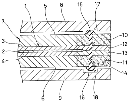
Next, a description will be given of one embodiment
of a method of manufacturing the fuel cell. The method
is as follows.
That is, first, as shown in Fig. 15, in accordance
with the same manner as the twelfth embodiment mentioned
above, the gas diffusion layer 5 is formed by integrally
carrying out the gasket material impregnating process
in the gasket material impregnation portion 10 of the
gas diffusion layer 5, and the gasket material
insulating spacer 12 forming process, and next, as shown
in Fig. 16, the UEA 7 is formed by integrally bonding
the gas diffusion layers 5 and 6 to both surfaces of
the membrane electrode complex 1. Next, as shown in
Fig. 17, the desired number of through holes 14 and
and manifolds are formed so as to extend through,
and next, as shown in Fig. 18, the gaskets 15 and 16
CA 02444246 2003-10-09
are formed, and next, as shown in Fig.. 19, the stack
is assembled by arranging the separators 8 and 9. Fig.
20 shows a cross sectional view including a gas
introduction portion (a gas communication groove) 62
for supplying a reaction gas within a separator surface,
in the cell stack in Fig. 19 which is assembled in
accordance with the manufacturing method mentioned
above. Since the gasket material impregnation portion
of the gas diffusion layer 5 is opposed to the gas
communication groove 62, the spacer 63 which is
conventionally required is unnecessary. Further,
since it. is not necessary to arrange the gasket in the
gasket material impregnation portion 10 of the gas
diffusion layer 5 opposing to the gas communication
groove 62, the through hole is not provided.
EFFECT OF THE INVENTION AND INDUSTRIAL APPLICABILITY
The present invention achieves the following
effect.
That is, first, in accordance with the fuel cell
on the basis of the first aspect of the present invention
provided with the structure mentioned above, it is
possible to prevent the separator and the UEA from being
broken due to the fastening after stacking, owing to
the structure and the operation mentioned above.
Further, it is possible to uniformly apply the fastening
pressure to all of the gaskets, it is possible to
46
CA 02444246 2003-10-09
securely obtain good seal, and it is possible to secure
a safety as well as an improvement of a power generating
efficiency. Further, it is possible to reduce a
manufacturing cost of the gasket. Further, in a
stacking step of alternately stacking the separator
and the UEA, the work can be easily carried out and
can be automated. Accordingly, it is possible to
reduce a cost for manufacturing the stack. Further,
even in the case that disassembly of the stack is
required, the work can be easily carried out without
breaking the structure material such as the separator,
the gasket, the UEA and the like, so that it is possible
to reuse and repair the structure material. Further,
it is possible to obtain a good seal performance without
'relation to the thickness of the UEA in the gasket
forming portion.
Further, in accordance with the fuel cell on the
basis of the second aspect of the present invention
provided with the structure mentioned above, since it
is possible to easily form the gasket, the insulating
spacer and the gasket material impregnation portion
owing to the structure and the operation mentioned above,
it is possible to reduce the cost for manufacturing
the stack. Further, it is possible to easily arrange
the insulating spacer in the gas diffusion layer.
Further, it is possible to apply a uniform fastening
47
CA 02444246 2003-10-09
force to all of the gaskets, it is possible to securely
obtain a good seal, and a safety can be secured as well
as an improvement of a power generating efficiency.
Further, in the stacking step of alternately stacking
the separator and the UEA, the work can be carried out
simple and can be automated. Accordingly, it is
possible to reduce the cost formanufacturing the stack.
Further, even in the case that disassembly is required
in the stack, it is possible to easily carry out the
work without breaking the construction material such
as the separator, the gasket, the UEA and the like,
so that it is possible to reuse and repair the structure
material.
Further, in accordance with the fuel cell on the
basis of the third aspect of the present invention
provided with the structure mentioned above, it is
possible to prevent the separator and the UEA from being
broken due to the fastening after stacking, owing to
the structure and the operation mentioned above.
Further, it is possible to apply a uniform fastening
force to all of the gaskets, it is possible to securely
obtain a good seal, and a safety can be secured as well
as an improvement of a power generating efficiency.
Further, it is possible to reduce the cost for
manufacturing the gasket. Further, since it is
possible to securely prevent the reaction gas from
48
CA 02444246 2003-10-09
leaking from the end portion of the gas diffusion layer,
the interface between the gas diffusion layer and the
insulating spacer, or the interface between the
insulating spacers, it is possible to improve the
safety.
Further, in accordance with the fuel cell on the
basis of the fourth aspect of the present invention
provided with the structure mentioned above, it is
possible to prevent the separator and the UEA from being
broken due to the fastening after stacking, owing to
the structure and the operation mentioned above.
Further, it is possible to apply a uniform fastening
force to all of the gaskets, it is possible to securely
obtain a good seal, and a safety can be secured as well
as an improvement of a power generating efficiency.
Further, it is possible to reduce the cost for
manufacturing the gasket. Further, in the stacking
step of alternately stacking the separator and the UEA,
the work can be carried out simply and can be automated.
Accordingly, it is possible to reduce the cost for
manufacturing the stack. Further, even in the case
that is required in the stack, it is possible to easily
carry out the work without breaking the construction
material such as the separator, the gasket, the UEA
and the like, so that it is possible to reuse and repair
the structure material.
49
CA 02444246 2003-10-09
Further, in accordance with the manufacturing
method on the basis of the fifth aspect of the present
invention provided with the structure mentioned above,
in the stacking step of alternately stacking the
separator and the UEA, the work can be carried out simply
and can be automated, owing to the structure and the
operation mentioned above. Accordingly, it is
possible to reduce the cost formanufacturing the stack.
Further, even in the case that is required in the stack,
it is possible to easily carry out the work without
breaking the construction material such as the
separator, the gasket, the UEA and the like, so that
it is possible to reuse and repair the structure
material.
Further, in accordance with the manufacturing
method on the basis of the sixth aspect of the present
invention provided with the structure mentioned above,
in addition to the same effects as those of the third
or fourth aspect mentioned above, the following effects
can be obtained, owing to the structure and the operation
mentioned above. That is, in the stacking step of
alternately stacking the separator and the UEA, the
work can be carried out simply and can be automated.
Accordingly, it is possible to reduce the cost for
manufacturing the stack.- Further, even in the case
that is required in the stack, it is possible to easily
i
CA 02444246 2003-10-09
carry out the work without breaking the construction
material such as the separator, the gasket, the UEA
and the like, so that it is possible to reuse and repair
the structure material. Further, it is possible to
widely reduce the manufacturing cost at a time of mass
production.
Further, in accordance with the manufacturing
method on the basis of the seventh aspect of the present
invention provided with the structure mentioned above,
the same effects as those of the sixth aspect mentioned
above can be obtained by using the adhesive rubber
material, owing to the structure and the operation
mentioned above.
Further, in accordance with the manufacturing
method on the basis of the eighth aspect of the present
invention provided with the structure mentioned above,
the same effects as those of the sixth aspect mentioned
above can be obtained by securing the surface roughness
of the gas diffusion layer and forming the gasket
thereon.
Further, in accordance with the fuel cell on the
basis of the ninth aspect of the present invention
provided with the structure mentioned above, in
addition to the same effects as those of the first to
fourth aspect mentioned above, the following effects
can be obtained, owing to the structure and the operation
51
CA 02444246 2003-10-09
mentioned above. That is, it is possible to easily
form the gasket in the gas diffusion layer and it is
possible to reduce the manufacturing cost. Further,
it is possible to prevent the reaction gas from leaking
from the end portion of the gas diffusion layer, and
the safety can be secured as well as the improvement
of the power generating efficiency.
Further, in accordance with the fuel cell on the
basis of the tenth aspect of the present invention
provided with the structure mentioned above, in
addition to the same effects as those of the first to
fourth aspect mentioned above, the following effects
can be obtained, owing to the structure and the operation
mentioned above. That is, it is possible to easily
form the gasket in the gas diffusion layer and it is
possible to reduce the manufacturing cost. Further,
it is possible to prevent the reaction gas from leaking
from the end portion of the gas diffusion layer, and
the safety can be secured as well as the improvement
of the power generating efficiency. Further, it is
possible to fix the gasket to the gas diffusion layer
without applying the adhesive agent to the gasket
forming portion.
Further, in accordance with the fuel cell on the
basis of the eleventh aspect of the present invention
provided with the structure mentioned above, in
52
CA 02444246 2003-10-09
addition to the same effects as those of the first to
fourth aspect mentioned above, the following effects
can be obtained, owing to the structure and the operation
mentioned above. That is, in addition that it is
possible to obtain a high gas seal performance against
the gasket leak from the end portion of the gas diffusion
layer, it is possible to obtain a high gas seal
performance against the leak in the interface between
the gas diffusion layer and the separator, so that the
safety can be secured as well as the improvement of
the power generating efficiency. Further, it is
possible to prevent the gas diffusion layers from
shorting between an anode pole and a cathode pole, at
a time when the through holes are provided after
integrating the UEA. Further, it is possible to
prevent a compressive buckling of the end portion of
the gas diffusion layer due to the stack fastening.
Further, in accordance with the gas diffusion
layer on the basis of the twelfth aspect of the present
invention provided with the structure mentioned above,
in addition to the same effects as those of the first
to fourth aspect mentioned above, the following effects
can be obtained, owing to the structure and the operation
mentioned above. That is, it is possible to prevent
the gas diffusion layers from shorting between an anode
pole and a cathode pole, at a time when the through
53
CA 02444246 2003-10-09
holes are provided after integrating the UEA. Further,
it is possible to prevent a compressive buckling of
the end portion of the gas diffusion layer due to the
stack fastening. Further, it is possible to reduce
the cost for manufacturing the UEA. Further, errors
in integrally bonding is reduced, and it is possible
to improve a yield ratio.
Further, in accordance with the gas diffusion
layer on the basis of the thirteenth aspect of the
present invention provided with the structure
mentioned above, the same effects as those of the first
to fourth aspect mentioned above can be obtained, owing
to the structure and the operation mentioned above.
Further, in accordance with the manufacturing
method on the basis of the fourteenth aspect of the
present invention provided with the structure
mentioned above, in addition to the same effects as
those of the first to fourth aspect mentioned above,
it is possible to reduce the cost for manufacturing
the UEA, owing to the structure and the operation
mentioned above.
Further, in accordance with the fuel cell on the
basis of the fifteenth aspect of the present invention
provided with the structure mentioned above, the same
effects as those of the first to fourth aspect mentioned
above can be obtained, owing to the structure and the
54
CA 02444246 2003-10-09
operation mentioned above.
Further, in accordance with the fuel cell on the
basis of the sixteenth aspect of the present invention
provided with the structure mentioned above, in
addition to the same effects as those of the first to
fourth aspect mentioned above, the following effects
can be obtained, owing to the structure and the operation
mentioned above. That is, since the specific
positioning jig is not required at a time of alternately
stacking the UEA and the separator, and it is possible
to easily stack, it is possible to reduce the cost for
manufacturing the stack. Further, it is possible to
achieve a high seal performance, and the safety can
be secured as well as the improvement of the power
generating efficiency. Further, it is possible to
prevent the UEA and the separator from being broken
in the end portion due to a buckling deformation at
a time of fastening the stack body.
Further, in accordance with the fuel cell on the
basis of the seventeenth aspect of the present invention
provided with the structure mentioned above, in
addition to the same effects as those of the first to
fourth aspect mentioned above, it is possible to reduce
the cost for manufacturing the UEA, owing to the
structure and the operation mentioned above.