Note: Descriptions are shown in the official language in which they were submitted.
CA 02444256 2003-10-16
WO 02/087689 PCT/US02/12167
INSULATING MEMBER FOR A MEDICAL ELECTRICAL LEAD
Reference to Priority Application
This application claims the benefit of U.S. Provisional Application No.
60/284,430, entitled "MEDICAL ELECTRICAL LEAD", incorporated herein by
reference in its entirety.
Field of the Invention
The present invention relates to medical electrical leads in general, and,
more
particularly, the present invention relates to maintaining electrical
isolation between
various electrodes and conductors of an implantable medical lead.
Background of the Invention
A wide assortment of implantable medical devices (IMDs) are presently known
and in commercial use. Such devices include cardiac pacemakers, cardiac
defibrillators,
cardioverters, neurostimulators, and other devices for delivering electrical
signals to a
portion of the body and/or receiving signals from the body. Pacemakers, for
example, are
designed to operate so as to deliver appropriately timed electrical
stimulation signals when
needed, in order to cause the myocardium to contract or beat, and to sense
naturally
occurnng conduction signals in the patient's heart.
Devices such as pacemakers, whether implantable or temporary external type
devices, are part of a system for interacting with the patient. In addition to
the pacemaker
device, which typically has some form of pulse generator, a pacing system
includes one or
more leads for delivering generated stimulation pulses to the heart and for
sensing cardiac
signals and delivering sensed signals from the heart back to the pacemaker. As
is known,
pacemakers can operate in either a unipolar or bipolar mode, and can pace the
atria or the
ventricles. Unipolar pacing requires a lead having only one distal electrode
for positioning
in the heart, and utilizes the case, or housing of the implanted device as the
other electrode
for the pacing and sensing operations. For bipolar pacing and sensing, the
lead typically
has two electrodes, a tip electrode disposed at the distal end of the lead,
and a ring
CA 02444256 2003-10-16
WO 02/087689 PCT/US02/12167
2
electrode spaced somewhat back from the distal end. Each electrode is
electrically
coupled to a conductive cable or coil, which tames the stimulating current or
sensed
cardiac signals between the electrodes and the implanted device via a
connector.
In order to perform reliably, cardiac pacing leads need to be positioned and
secured
at a targeted cardiac tissue site in a stable manner. One common mechanism for
securing
an electrode position is the use of a rotatable fixation helix. The helix
exits the distal end
of the lead and can be screwed into the body tissue. The helix itself may
serve as an
electrode or it may serve as an anchoring mechanism to locate an electrode
mounted to the
lead body adjacent a targeted tissue site. The fixation helix may be coupled
to a drive
shaft that is further connected to a coiled conductor that extends through the
lead body as
generally described in U.S. Pat. No. 4,106,512 to Bisping et al. A physician
rotates the
coiled conductor at a proximal end to cause rotation of the fixation helix via
the drive
shaft. As the helix is rotated in one direction, the helix is secured in the
cardiac tissue.
Rotation in the opposite direction removes the helix from the tissue to allow
for
repositioning of the lead at another location.
Combination devices are available for treating cardiac arrhythmias that are
capable
of delivering shock therapy for cardioverting or defibrillating the heart in
addition to
cardiac pacing. Such a device, commonly known as an implantable cardioverter
defibrillator or "ICD", uses coil electrodes for delivering high-voltage shock
therapies.
An implantable cardiac lead used in combination with an ICD may be a
quadrapolar lead
equipped with a tip electrode, a ring electrode, and two coil electrodes. A
quadrapolar
lead requires four conductors extending the length of the lead body in order
to provide
electrical connection to each electrode.
Pacemaker systems, as well as other medical devices such as those mentioned
above, can utilize a wide variety of lead designs. Many considerations are
taken into
account when optimizing the design of a lead. For example, minimizing lead
size is
important since a smaller device is more readily implanted within the cardiac
structures or
coronary vessels of a patient. Electrical insulation between multiple
conductors and their
associated electrodes is crucial to providing the desired therapeutic effect
of electrical
stimulation. With the increased number of insulated conductors required in
quadrapolar
leads, the diameter of the lead body is increased. It is desirable, however,
to minimize the
CA 02444256 2003-10-16
WO 02/087689 PCT/US02/12167
3
lead body diameter while maintaining proper insulation and the structural
integrity of the
lead.
Moreover, providing features that make a lead easier to implant and extract
allows
the clinician to complete the associated surgical procedure more safely and in
less time.
Finally, an optimized lead design is ideally manufactured using techniques
that are
relatively simple and easy to verify. The resulting product should be easy to
test so that
manufacturing defects can be detected prior to the implant of the device
within a patient.
What is needed, therefore, is an improved lead design that takes all of the
foregoing
factors into account, thereby providing a device that can be safely and
efficiently
deployed, used, and, if necessary, extracted.
Summary of the Invention
The present invention is realized by providing a medical electrical lead that
includes a lead body having a lead body lumen, an electrode head assembly
fixedly
engaged with the lead body and having an electrode head assembly lumen
communicating
I S with the lead body lumen, and a conductor extending within the lead body
lumen and the
head assembly lumen. An insulating member extends through the electrode head
assembly lumen and the lead body lumen, electrically isolating the conductor.
In a preferred embodiment, the insulating member is formed from
polytetrafluoroethylene (PTFE). The PTFE member can be made thinner than other
polymers that might be used for insulation allowing the overall lead body
diameter to be
minimized. The PTFE member further provides a low-interference and low-
friction
surface for the rotation of the coiled conductor during advancement or
retraction of the
helical tip electrode.
The insulating member is preferably etched or otherwise treated to enhance an
adhesive bond between the insulating member and the electrode head assembly,
which
houses a tip electrode. The bond between the insulating member and the
electrode head
assembly enables the lead body to be coupled to the electrode head assembly at
a butt
joint, simplifying manufacturing processes. The bond between the insulating
member and
the electrode head assembly, which is preferably fabricated from polyurethane,
provides
strain relief to the conductor during lead implantation or extraction. The
insulating
member provided in accordance with the present invention thus provides proper
insulation
CA 02444256 2003-10-16
WO 02/087689 PCT/US02/12167
4
using a minimal amount of space and further allows a strengthening bond
between
modular components of a medical lead.
Another aspect of the present invention is a method for assembling a medical
electrical lead that includes fixedly engaging an insulating member, for
electrically
S isolating a conductor, within a first lumen at a proximal end of an
electrode head
assembly, inserting the insulating member within a second lumen of a distal
end of a lead
body, and fixedly engaging the proximal end of the electrode assembly and the
distal end
of the lead body.
Brief Descriution of the Drawings
FIG. 1 is a plan view of an implantable cardiac lead that may be utilized in
accordance with the present invention;
FIG. 2 is a cross-sectional view of a multi-lumen lead body of the lead shown
in
FIG. 1;
I S FIG. 3 is a side, cut-away view of a distal end of the lead shown in FIG.
1; and
FIG. 4 is a perspective view of the modular components used in assembling the
distal end of the lead shown in FIG. 3.
Detailed Description of the Invention
FIG. 1 is a plan view of an implantable cardiac lead that may be used in
accordance with the present invention, embodied as a transvenous cardiac
defibrillation
lead. As illustrated in FIG. 1, a lead 10 includes an elongated lead body 12
having a
connector assembly 16 at a proximal end of the lead 10 for connecting to an
implantable
device, and an electrode head assembly 14 at a distal end of the lead 10 for
carrying one or
more electrodes. Lead 10 is shown as a quadrapolar lead including, at or near
the distal
end, a helical tip electrode 30, a ring electrode 50, a right ventricular (RV)
defibrillation
coil 38 and a superior vena cava (SVC) defibrillation coil 40. The helical tip
electrode 30
and ring electrode 50 may be utilized to sense cardiac signals and/or deliver
pacing pulses
to a patient. One of the defibrillation coils 38 or 40 serves as the cathode
while the other
serves as the anode during delivery of a defibrillation shock to a patient as
a result of a
detected tachycardia or fibrillation condition.
CA 02444256 2003-10-16
WO 02/087689 PCT/US02/12167
The lead body 12 takes the form of an exfiruded tube of biocompatible plastic
such
as silicone rubber. Multiple lumens located within the lead body 12, carry
four insulated
conductors from the connector assembly 16 to the corresponding electrodes 30,
50, 38 and
40 located at or near the distal end of the lead 10. The multi-lumen lead body
12 may
correspond generally to that disclosed in U. S. Pat. No. 5,584,873 issued to
Shoberg et al.,
incorporated herein by reference in its entirety. Three of the insulated
conductors carned
by lead body 12 are stranded or cabled conductors, each electrically coupled
to one of the
ring electrode 50, RV coil 38 and SVC coil 40. The cabled conductors may
correspond
generally to the conductors disclosed in U.S. Pat. No. 5,246,014, issued to
Williams et al.,
incorporated herein by reference in its entirety. A fourth, coiled conductor
extends the
length of the lead body 12 and is coupled to the helical tip electrode 30.
In this embodiment, the helical tip electrode 30 functions as an electrode for
cardiac pacing and/or sensing and as an active fixation device for anchoring
the lead 10 in
a desired position. In other embodiments that may employ aspects of the
present
invention, a helical tip may function only as an active fixation device.
Reference is made
to U.S. Patent No. 4,217,913 to butcher, incorporated herein by reference in
its entirety.
Therefore, the helical tip electrode 30 may also be referred to herein as a
"fixation helix."
The connector assembly 16 has multiple connector extensions 18, 20, and 22
arising from a trifurcated connector sleeve, typically formed of silicone
rubber. The
connector extensions 18, 20, and 22 couple the lead 10 to an implantable
medical device
such as an implantable cardioverter defibrillator (ICD).
Connector extension 20 is shown as a bi-polar connector including a connector
ring 24 and a connector pin 25. Connector extension 20 houses the cabled
conductor that
is electrically coupled to the connector ring 24 at its proximal end and to
the ring electrode
50 at its distal end. The connector extension 20 also houses the coiled
conductor that is
electrically coupled to the connector pin 25 and extends to the tip electrode
30. During a
lead implant or explant procedure, rotation of the connector pin 25 relative
to the
connector assembly 16 causes corresponding rotation of the coiled conductor
and
advancement or retraction of the helical tip electrode 30 in the fashion
generally described
in U.S. Pat. No. 4,106,512 to Bisping et al., incorporated herein by reference
in its
entirety. By advancing the tip electrode 30, the electrode 30 can be actively
fixed in
CA 02444256 2003-10-16
WO 02/087689 PCT/US02/12167
6
cardiac tissue. A stylet 32 may be advanced within an inner Iumen of the
coiled conductor
to the distal end of the lead 10 to aid in lead placement during an implant
procedure.
The connector extension 18 carnes a single connector pin 52 that is
electrically
coupled to an insulated cable extending the length of the lead body 12 and
electrically
coupled to the RV coil 38. The connector extension 22 carries a connector pin
42 that is
electrically coupled to a respective insulated cable that is further coupled
to the SVC coil
40.
FIG. 2 is a cross-sectional view of a multi-lumen lead body of the lead of
FIG. 1.
As illustrated in FIG. 2, the lead body 12 includes four lumens I02, 122, 124,
and 126.
Lumen 102 carries the coiled conductor 26 that is coupled to the helical tip
electrode 30.
In accordance with the present invention, the conductor 26 is shown surrounded
by
insulation tubing 120. A stylet 32 may be advanced within the lumen 34 of the
coiled
conductor 26. Lumen 122 carries an insulated cable 110 that is electrically
coupled at a
proximal end to the connector ring 24 and at a distal end to the ring
electrode 50. Lumen
1 S 124 carries an insulated cable 112 that is electrically coupled at a
proximal end to the
connector pin 52 and at a distal end to the RV coil 38. Lumen 126 carries an
insulated
cable 114 that is electrically coupled at a proximal end to the connector pin
42 and at a
distal end to the SVC coil 40.
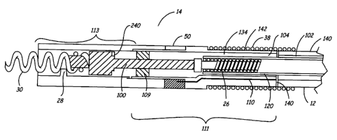
FIG. 3 is a side cutaway view of the distal end of the lead 10 showing a
detailed
view of the electrode head assembly 14 and the electrodes 30, 50 and 38. The
molded,
tubular electrode head assembly 14 includes two members, a distal electrode
head
assembly 113 and a proximal electrode head assembly 111. The distal and
proximal
electrode head assemblies 113 and 111 are preferably formed from a relatively
rigid
biocompatible plastic. For example, assemblies 1 I3 and 111 may be fabricated
from
molded polyurethane. The proximal electrode head assembly 111 is coupled to
the multi-
lumen lead body 12, typically formed from a relatively more compliant plastic
such as
silicone rubber, at a joint 140. The lumen 104 within the proximal electrode
head
assembly 111 communicates with the lumen 102 within the lead body 12 for
carrying the
coiled conductor 26 extending between the tip electrode 30 and the connector
ring 24. In
FIG. 3, the ring electrode 50 is shown coupled to the cable 110, and the RV
coil 38 is
CA 02444256 2003-10-16
WO 02/087689 PCT/US02/12167
shown positioned on the outer diameter of the proximal electrode head assembly
I 11 and
the lead body 12.
FIG. 3 further shows the helical tip electrode 30 electrically coupled to the
coiled
conductor 26 via a drive shaft 100. One particular advantage of fabricating
the electrode
head assembly 14 from polyurethane components is that polyurethane components
may be
made transparent. This transparency allows for inspection of the weld that
affixes helical
tip electrode 30 to the distal end of the drive shaft 100 so that lead
integrity is better
verified. The electrode 30 and drive shaft 100 are preferably fabricated of a
biocompatible
metal such as platinum iridium alloy. The coiled conductor 26 extends to the
proximal
connector assembly 16. Rotation of the connector pin 25 at the proximal end of
coiled
conductor 26 causes corresponding rotation of the distal end of the coiled
conductor 26 to,
in turn, cause rotation of the drive shaft 100. This rotation results in
extension or
retraction of helical tip electrode 30. A guide 28 actuates the helical tip 30
as it is
advanced or retracted. The lead 10 may include a drive shaft seal 109
encircling the drive
shaft 100. The drive shaft seal 109, which may be formed of silicone or any
other
elastomer, is housed within the proximal electrode head assembly 111.
One problem with quadrapolar leads involves maintaining electrical isolation
between the various electrodes and conductors in the system. For example, when
delivering pacing pulses to a patient, current is ideally supplied via coiled
conductor 26
and helical tip electrode 30 to body tissue surrounding the tip electrode 30.
Most of this
current then travels through the body tissue back to ring electrode 50 and is
then carried
back to the implantable device via the cable 110. However, if electrical
isolation is not
maintained between the coiled conductor 26 and the RV coil 38, current may
travel from
the RV coil 38 to the coiled conductor 26 when high-energy defibrillation
shocks are
delivered, potentially injuring tissue in contact with the helical tip
electrode 30.
The current invention utilizes an insulating member, such as a thin insulation
tube
120, to electrically isolate the coiled conductor 26 from RV coil 38 and ring
electrode 50.
The insulation tube 120 extends from the lumen 104 within the proximal
electrode head
assembly 111, through the lumen 102 within the lead body 12, to the connector
assembly
16. The insulation tube 120 is preferably a polymer having a high dielectric
strength such
as PTFE or ethyl tetrafluoroethylene (ETFE). The properties of PTFE are
particularly
CA 02444256 2003-10-16
WO 02/087689 PCT/US02/12167
8
suited for functioning as the insulation tubing around coiled conductor 26
because PTFE
can be made into a tube with a smaller diameter and thinner wall than other
polymers,
such as silicone rubber or urethane, allowing overall lead size to be
minimized.
Furthermore, the PTFE tubing provides a low-interference and low-friction
interface with
the coiled conductor 26, which must easily rotate within the insulation tube
120 in order to
advance or retract the fixation helix 30.
As illustrated in FIGS. 2 and 3, an inner lumen 130 of insulation member tube
120
houses coiled conductor 26, and prevents current leakage between the coiled
conductor 26,
RV coil 38 and ring electrode 50. In a preferred embodiment of the invention,
an outer
surface 132 of the insulation tube 120 is bonded to an inner surface 134 of
lumen 104
within the proximal electrode head assembly 111 using an epoxy, polyurethane
or other
adhesive. Urethane adhesive is preferred because it is readily applied using a
solvent,
making the manufacturing process more efficient. The outer surface 132 of the
insulation
tubing 120 is preferably etched to facilitate bonding with adjacent
components, such as the
inner surface 134 of lumen 104. Additionally, the polyurethane adhesive
provides an
improved bond between PTFE insulation tube 120 and the urethane walls
surrounding the
lumen 104 over silicone adhesives. The ability to form a complete seal further
prevents
current leakage between the distal end of coiled conductor 26, RV coil 38, and
ring
electrode 50.
By bonding the insulation tubing 120 to the proximal electrode head assembly
111,
a modular lead design is possible in which the proximal electrode head
assembly is joined
to the lead body 12 at the butt joint 140 shown in FIG. 3. ,
FIG. 4 is a perspective view illustrating the modularity that may be provided
by the
electrode head assemblies 111 and 113 and the mufti-lumen lead body 12 with
use of the
insulation tubing 120. Arrows 200 and 201 show the manner in which the distal
and
proximal electrode head assemblies 113 arid 111 are joined together and with
lead body
12. According to one method of assembling this lead 10, the insulation tubing
120 may be
inserted into lumen 104 of the proximal electrode head assembly 111 and bonded
thereto
using, for example, a urethane adhesive. Next, the unbonded proximal end of
the
insulation tubing 120 may be inserted into lumen 102 at the distal end of the
lead body 12.
A bonding process may then be utilized to bond a proximal end 136 of the
proximal
CA 02444256 2003-10-16
WO 02/087689 PCT/US02/12167
9
electrode head assembly 111 to a distal end 138 of the silicone lead body 12
at butt joint
140 so that the proximal end 136 is fixedly positioned adjacent to the distal
end 138. For
example, a silicone adhesive may be used to facilitate this bonding of the
proximal end
136 to the distal end 138. The insulation tubing 120 provides mechanical
stability,
electrical isolation, added lead body strength, and improved flex life in the
vicinity of the
butt joint 140.
The assembly of lead 10 may also include bonding the RV coil 38 to an outer
portion 140 of the lead body 12 and an outer portion 142 of the proximal
electrode head
assembly 111, as in the position shown in FIG. 3. The grooved area 142 of
assembly 111
provides an adhesive grip and aids in holding the RV coil 38 in place. The
placement of
RV coil 38 across the butt joint 140 provides additional stability to the
joint 140. The ring
electrode 50 is captured in the position shown in FIG. 3 between the distal
electrode head
assembly 113 and the proximal electrode head assembly 111 after they are
joined. The
cabled conductor 110 coupled to the ring electrode 50 (FIG. 3) provides
additional stress
1 S relief to the butt joint 140.
FIG. 4 further shows an optional electrode head peg 202 used in conjunction
with
lumen 126 to provide alignment of the proximal electrode head assembly 111 and
the lead
body 12 during the manufacturing process. As shown previously in FIG. 2, the
lumen 126
houses the cable 114 (shown in FIG. 2) that extends from connector assembly 16
to the
SVC coil 40. Distal to the SVC coil 40, the lumen 126 is empty, advantageously
providing a port at the distal end of the lead body 12 in which to engage the
electrode head
peg 202. The electrode head peg 202 may be bonded within lumen 126 using an
adhesive,
preferably a silicone adhesive, to provide additional strength and strain
relief to the butt
joint 140.
The modular assembly provided by the embodiments of the invention described
above provides several advantages. The assembly method allows the proximal and
distal
electrode head assemblies 111 and 113 to be manufactured separately and
coupled to the
lead body 12 later in the manufacturing process. The modular design makes the
electrode
head assemblies 111 and 113 easier to inspect and test, and also simplifies
the lead
assembly process. By utilizing the insulation tubing 120, a method for joining
a
polyurethane electrode head assembly 14 and a silicone lead body 12 in a
stable, reliable
CA 02444256 2003-10-16
WO 02/087689 PCT/US02/12167
manner can be realized without increasing the lead diameter at the joint or
requiring
difficult manufacturing processes. It may further be noted that the RV
defibrillation coil
38 and the optional electrode head peg 202 provide additional strain relief at
the butt joint
140.
5 The lead described above with respect to the current inventive lead system
is a
quadrapolar high-voltage lead of the type that may be used in conjunction with
an
implantable cardioverter defibrillator. However, it will be understood by one
skilled in the
art that any or all of the inventive aspects described herein may be
incorporated into other
types of lead systems. For example, one or more of the aspects may be included
in a
10 unipolar or multipolar pacing lead. An alternative lead design may include
any
combination of a tip electrode, one or more ring electrodes, or one or more
coil electrodes
for use in pacing, sensing, and/or shock delivery. Alternatively, drug-
delivery or other
electrical stimulation leads may employ aspects of the current inventive lead
system for
minimizing lead diameter, ensuring reliability, and simplifying assembly and
testing
methods. As such, the above disclosure should be considered exemplary, rather
than
limiting, with regard to the following claims.