Language selection

Search

Patent 2444340 Summary

Third-party information liability

Some of the information on this Web page has been provided by external sources. The Government of Canada is not responsible for the accuracy, reliability or currency of the information supplied by external sources. Users wishing to rely upon this information should consult directly with the source of the information. Content provided by external sources is not subject to official languages, privacy and accessibility requirements.

Claims and Abstract availability

Any discrepancies in the text and image of the Claims and Abstract are due to differing posting times. Text of the Claims and Abstract are posted:

  • At the time the application is open to public inspection;
  • At the time of issue of the patent (grant).
(12) Patent: (11) CA 2444340
(54) English Title: NIPPLE FOR HOT WATER TANK CONDUITS
(54) French Title: MAMELON POUR CANALISATIONS DE CHAUFFE-EAU
Status: Deemed expired
Bibliographic Data
(51) International Patent Classification (IPC):
  • F24H 9/12 (2006.01)
  • F16L 59/16 (2006.01)
  • F24H 9/00 (2006.01)
(72) Inventors :
  • LESAGE, CLAUDE (Canada)
(73) Owners :
  • MICLAU - S.R.L. INC. (Canada)
(71) Applicants :
  • GIANT FACTORIES INC. (Canada)
(74) Agent:
(74) Associate agent:
(45) Issued: 2008-07-08
(22) Filed Date: 2003-10-07
(41) Open to Public Inspection: 2005-04-07
Examination requested: 2006-02-08
Availability of licence: N/A
(25) Language of filing: English

Patent Cooperation Treaty (PCT): No

(30) Application Priority Data: None

Abstracts

English Abstract

A nipple for connection to an outer metal casing of a hot water heater for coupling a water conduit to an inner casing of the hot water heater is described. The nipple is a hollow tube having opposed threaded end portions. A thermally insulating sleeve is provided about the hollow tube intermediate the opposed threaded end portions. The nipple is adapted for connection in a hole formed in the outer metal casing with the thermally insulating sleeve in contact with a circumferential edge of the hole to insulate the metal casing from the nipple.


French Abstract

Le présent abrégé décrit un mamelon de raccordement à une enveloppe métallique extérieure d'un chauffe-eau pour coupler une conduite d'eau à une enveloppe intérieure du chauffe-eau. Ce mamelon est un tube creux ayant des parties d'extrémité filetées opposées. Un manchon d'isolation thermique encerclant le tube creux est situé à mi-distance entre les extrémités filetées opposées. Le mamelon est adapté pour le raccordement, dans un trou formé dans l'enveloppe métallique extérieure, avec le manchon d'isolation thermique en contact avec la circonférence du trou afin d'isoler l'enveloppe métallique du mamelon.

Claims

Note: Claims are shown in the official language in which they were submitted.


-5-

I CLAIM,

1. A nipple for connection to an outer metal casing of a
hot water heater for coupling a water conduit to an inner
casing of said hot water heater, said nipple being a hollow
tube having opposed threaded end portions, and a thermally
insulating sleeve about said hollow tube intermediate said
opposed threaded end portions, said nipple being adapted for
connection in a hole formed in said outer metal casing with
said thermally insulating sleeve in contact with a
circumferential edge of said hole to insulate said metal
casing from said nipple.

2. A nipple as claimed in claim 1 wherein said thermally
insulating sleeve is a plastic shroud secured about said
nipple.

3. A nipple as claimed in claim 1 wherein said thermally
insulating sleeve is a plastic coupling.

4. A nipple as claimed in claim 3 wherein said coupling
has a tubular body portion secured in press-fit about said
hollow tube, and a transverse circumferential flange about a
top end of said tubular body portion to overlie an outer
surface of said outer metal casing about said hole.

5. A nipple as claimed in claim 4 wherein said plastic
coupling is moulded from polyethylene plastic material.

6. A nipple as claimed in claim 2 wherein said plastic
shroud is secured to said hollow tube by heat shrink.

7. A nipple as claimed in claim 1 wherein there are
two of said nipples secured to a top wall of said outer
metal casing, one of said nipples being connected to an
inlet water conduit and the other to an outlet water
conduit.


Description

Note: Descriptions are shown in the official language in which they were submitted.


CA 02444340 2003-10-07
NIPPLE FOR HOT WATER TANK CONDUITS
TECHNICAL FIELD
Coool7 The present invention relates to a nipple for
connection to an outer metal casing of a hot water heater
for coupling a water conduit to an inner casing of the hot
water heater and wherein the nipple is substantially
insulated from the outer metal casing.
BACKGROUND ART
Cooo21 The construction of a hot water heater consists
essentially of an inner tank which constitutes a reservoir
in which water is heated. The inner tank is insulated from
an outer casing by spacing an outer casing from the inner
tank and filling the interstices with an insulating foam or
fibreglass material. 2'he top of the tank is provided with
conduits to admit water into the tank and to remove hot
water from the tank. These conduits are usually
interconnected to the cover of the outer casing through an
interconnecting nipple and bushing. Usually, copper piping
is connected to the outer end of the nipples . The nipples
are secured to the top wall of the outer metal casing by
metal bushings.
tooo37 It has been found that an important amount of
heat is lost through the outer casing top wall due to its
contact with these nipples. The nipple is a metal tube
which is highly thermally conductive as well as its
couplings. Accordingly, heat exchange between the nipple is
made with the top wall of the outer casing which is also
constructed of metal. This heat is propagated throughout
the top wall of the casing and into the other nipple and the
tubes and the metal conduits secured thereto. Holes are
presently punched in the top wall of the outer casing and
are about 1316 inch less than the OD of the nipples. These
holes are also not always concentric with the nipple OD.
Looo4~ There is a requirement to render hot water
heaters thermally efficient and this is done by isolating


CA 02444340 2003-10-07
the inner tank from the outer casing all about the tank.
Such inner tanks, and the ones which are heated by
electrical resistive heating elements, are mounted on foam
bases whereby the tank is well isolated at the base and all
around. However, in order to render the tank more
efficient, we have discovered that there is a need to
insulate these nipples to substantially reduce the heat loss
which is transmitted through the top wall of the outer
casing.
SUMMARY OF INVENTION
foo05~ It is therefore a feature of the present
invention to provide a nipple for connection to an outer
metal casing of a hot water heater and which substantially
overcomes the above-mentioned disadvantage of the prior art.
tooos, According to the above feature, from a broad
aspect, the present invention provides a nipple for
connection to an outer metal casing of a hot water heater
for coupling a water conduit to an inner casing of the hot
water heater. The nipple is a hollow tube having opposed
threaded end portions. A thermally insulating sleeve is
provided about the hollow tube intermediate the opposed
threaded end portions. The nipple is adapted for connection
in a hole formed in the outer metal casing with the
thermally insulating sleeve in contact with a
circumferential edge of the hole to insulate the metal
casing from the nipple.
BRIEF DESCRIPTION OF DRAWINGS
fooa~l A preferred embodiment of the present invention
will now be described with reference to the accompanying
drawings in which:
tooo87 FIGURE 1 is a partly fragmented top view of a
hot water heater showing the connection of nipples in a top
wall of an outer casing for connecting conduits to the inner
tank of the hot water heater;


CA 02444340 2003-10-07
- 3 -
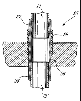
Cooo9) FIGURE 2 is a fragmented section view showing
one embodiment of the nipple constructed in accordance with
the present invention;
Lo001o~ FIGURE 3 is a top view of the top wall of the
outer casing of a hot water heater;
toooll, FIGURE 4 is a fragmented section view similar to
Figure 2 but showing another embodiment of the nipple
constructed in accordance with the present invention; and
toool2~ FIGURE 5 is a top view of Figure 4.
DESCRIPTION OF PREFERRED EMBODIMENTS
foooZ3~ Referring now to the drawings, and more
specifically to Figure 1, there is shown generally at 10, a
fragmented top section of a domestic hot water heater. Hot
water heaters comprise an inner steel tank 11 in which water
is supplied by an inlet conduit 13 and hot water is taken
from the inner tank 11 through an outlet conduit 14. The
inner tank 11 is surrounded by an outer casing 15 which
usually comprises a cylindrical metal sleeve 16 and a top
cover 17. The bottom of the tank is also insulated and sits
on a dish which is secured to the cylindrical metal sleeve
16. Insulating wool or foam material 18 is placed or
injected in the space between the outer casing and the inner
tank whereby to insulate the hot inner tank which contains
the hot water from the outer casing.
foooi4~ As herein shown, the inlet and outlet conduits
13 and 14 are connected to the inner tank through a metal
nipple 19 and 19' which are usually secured to the top cover
17 or top wall by metal bushings 20. However, they could
also be connected in a top region of the side wall 16. As
previously described, a problem with these nipples and
bushings is that they conduct heat, and accordingly, hot
water leaving the hot water tank 10 through the outlet
conduit 14 is absorbed in the top cover and this constitutes
heat loss which translates in energy loss, resulting in an


CA 02444340 2003-10-07
- 4 -
increase in the consumption of energy to heat the water
within the inner tank.
foooi5l With reference now to Figure 2, there is shown
the nipple 25 constructed in accordance with the present
invention. The nipple is a hollow metal tube 26 provided
with opposed threaded end portions, namely an outer threaded
portion 27 and an inner threaded portion 28. The inlet and
outlet conduits are connected to the outer threaded portion
27 whereas the inner threaded portion 28 is connected to
interconnecting conduits 21 and 21' or directly to the inner
tank 11 top wall through appropriate bushings 22 and 22'.
The hollow metal tube 26 of the nipple 25 is provided with a
thermally insulating sleeve 29 thereabout and disposed
intermediate the opposed threaded end portions 27 and 28.
As herein shown, the thermally insulating sleeve 29 is a
plastic shroud which is secured to the hollow tube by heat
shrink. It is also dimensioned for press-fit within the
holes 30 provided in the top wall or top cover 17 of the
outer casing of the hot water heater as shown in Figure 3.
Accordingly, the nipple 25 is insulated from the top wall
whereby to substantially reduce heat loss between the nipple
and the top wall 17.
toool6~ Referring now to Figure 4, there is shown
another embodiment of the thermally insulating sleeve and,
as herein shown., the sleeve is provided as a polyethylene
plastic coupling 31 which defines a~ tubular body portion 32
which is dimensioned for press-fit into the holes 30 made in
the outer casing. A transverse circumferential flange 33 is
formed integral with the tubular body portion 32 and
overlies the top surface of the top cover 17 about the hole
30. The coupling 31 is also an injection moulded part which
is press-fitted about the nipple 25.
foool~~ It is within the ambit of the present invention
to cover any obvious modifications of the examples of the
preferred embodiment described herein, provided such
modifications fall within the scope of the appended claims.

Representative Drawing
A single figure which represents the drawing illustrating the invention.
Administrative Status

For a clearer understanding of the status of the application/patent presented on this page, the site Disclaimer , as well as the definitions for Patent , Administrative Status , Maintenance Fee  and Payment History  should be consulted.

Administrative Status

Title Date
Forecasted Issue Date 2008-07-08
(22) Filed 2003-10-07
(41) Open to Public Inspection 2005-04-07
Examination Requested 2006-02-08
(45) Issued 2008-07-08
Deemed Expired 2018-10-09

Abandonment History

There is no abandonment history.

Payment History

Fee Type Anniversary Year Due Date Amount Paid Paid Date
Registration of a document - section 124 $100.00 2003-10-07
Application Fee $300.00 2003-10-07
Registration of a document - section 124 $100.00 2004-05-13
Maintenance Fee - Application - New Act 2 2005-10-07 $100.00 2005-08-05
Request for Examination $800.00 2006-02-08
Maintenance Fee - Application - New Act 3 2006-10-09 $100.00 2006-09-19
Maintenance Fee - Application - New Act 4 2007-10-09 $100.00 2007-10-09
Final Fee $300.00 2008-04-07
Maintenance Fee - Patent - New Act 5 2008-10-07 $200.00 2008-10-07
Maintenance Fee - Patent - New Act 6 2009-10-07 $200.00 2009-07-14
Maintenance Fee - Patent - New Act 7 2010-10-07 $200.00 2010-08-03
Maintenance Fee - Patent - New Act 8 2011-10-07 $200.00 2011-07-13
Maintenance Fee - Patent - New Act 9 2012-10-09 $200.00 2012-09-12
Maintenance Fee - Patent - New Act 10 2013-10-07 $250.00 2013-07-11
Maintenance Fee - Patent - New Act 11 2014-10-07 $250.00 2014-09-03
Maintenance Fee - Patent - New Act 12 2015-10-07 $250.00 2015-06-18
Maintenance Fee - Patent - New Act 13 2016-10-07 $250.00 2016-07-14
Owners on Record

Note: Records showing the ownership history in alphabetical order.

Current Owners on Record
MICLAU - S.R.L. INC.
Past Owners on Record
GIANT FACTORIES INC.
LESAGE, CLAUDE
Past Owners that do not appear in the "Owners on Record" listing will appear in other documentation within the application.
Documents

To view selected files, please enter reCAPTCHA code :


To view images, click a link in the Document Description column. To download the documents, select one or more checkboxes in the first column and then click the "Download Selected in PDF format (Zip Archive)" or the "Download Selected as Single PDF" button.

List of published and non-published patent-specific documents on the CPD .

If you have any difficulty accessing content, you can call the Client Service Centre at 1-866-997-1936 or send them an e-mail at CIPO Client Service Centre.


Document
Description 
Date
(yyyy-mm-dd) 
Number of pages   Size of Image (KB) 
Abstract 2003-10-07 1 19
Description 2003-10-07 4 218
Drawings 2003-10-07 2 65
Claims 2003-10-07 1 44
Representative Drawing 2004-02-06 1 18
Cover Page 2005-03-23 1 43
Drawings 2006-02-08 2 56
Cover Page 2008-06-10 1 41
Representative Drawing 2008-06-10 1 16
Assignment 2003-10-07 4 164
Assignment 2004-01-27 4 128
Correspondence 2004-02-27 1 30
Prosecution-Amendment 2006-02-08 1 38
Prosecution-Amendment 2006-02-08 6 168
Correspondence 2008-04-07 2 57
Correspondence 2014-04-04 3 92
Correspondence 2014-04-25 1 17
Correspondence 2014-04-25 1 20