Note: Descriptions are shown in the official language in which they were submitted.
CA 02444368 2003-10-03
E3y Express Mail # EV 160129268US
FURNITURE WITH VERTICALLY MOVABLE FLAT PANEL DISPLAY SCREEN
BACKGROUND ~F THE INVENTION
1. Field of the Invention
The invention relates to furniture, in particular a modular furniture assembly
having a vertically movable mounting panel carrying a display screen.
2. Description of the Related Art
Furniture designed to house home entertainment systems typically has cabinets
and shelves far a television, stereo system, VCR and other components, as well
as space for
storing records, CDs, and cassettes, and further providing space far
displaying bric-a-brac,
photographs, etc. Likewise, computer work stations have cabinets and shelves
for a computer,
a computer monitor, peripherals, and work-related items. What these systems
have in
common is the requirement of a space to accommodate a display screen which
typically
functions as a television (TV} and/or a computer monitor. A shortcoming of
this arrangement
is that the display screen takes up a fixed amount of space in the furniture,
which space can
serve no other purpose.
In recent years, display screens have been developed by a number of
manufacturers that are flat and relatively thin in comparison to CRT's
(cathode ray tubes).
These are becoming increasingly more economical to own. The technology applied
in these
screens is LCD (liquid crystal display) or plasma. These screens utilize the
same electronic
signal information as a conventional CRT. One of the chief advantages of such
screens is that
2
CA 02444368 2003-10-03
By Express Mail # EV16Q129268US
they do not require any substantial depth, and may thus be designed as a
relatively flat package
which can be hung on a wall. Another advantage is that they are available in
large sizes, e.g.
even in widths exceeding 50 in., and permit viewing from a considerable
distance.
It would be desirable to incorporate a flat screen into a piece of furniture
such as
a home entertainment system or workstation. However, fixing the screen into a
position within
the furniture piece would render the space it occupies, and also the space in
front of it,
unusable for anything else. Likewise, if the screen were mounted toward the
front of the
furniture piece, this would render the space behind it inaccessible. Thus, a
considerable
amount of space would be rendered unusable, particularly where a large size
screen is desired.
This is a significant disadvantage, particularly where space is at a premium,
such as in an
urban apartment. lVlounting such a screen elsewhere, i.e. outside the
furniture piece, would
not only separate it from other components of the entertainment system or
workspace and
require connection with unsightly wiring, but would take up wall space which
could be used
otherwise .
3
CA 02444368 2003-10-03
By Express Mail # Ev160129268US
SUMMARY OF THE INVENTIfOlel
One object of the invention is to provide mufti-purpose furniture arranged to
mount a flat display screen so as to occupy no more than minimal space
therein.
Another object of tile invention is to provide mufti-purpose furniture
arranged to
mount a flat display screen so as to not impede access to space theiein.
A further object of the invention is to provide a furniture-mounted display
screen arranged so it can be conveniently and safely wired to receive signals
from any one of
multiple sources located conveniently to the screen.
Yet another object of the invention is to enable mounting a flat display
screen in
a corner of a room.
Still another object of the invention is to provide a flat display -screen
mounted
so as to be vertically adjustable on a piece of furniture.
An additional object of the invention is to provide an electrically powered,
vertically adjustable mounting for a flat display screen on a piece of
furniture arranged so that
the powered motion is controlled so as to avoid injury to users.
One other object of the invention is to provide an electrically powered,
vertically adjustable mounting for a flat display screen on a piece of
furniture arranged so that
exposure of the screen to damage during an off mode is minimized.
These and other objects are attained in accordance with one aspect of the
invention which provides a base having a front, a rear, and a pair of opposed
sides; a pair cif
lifting mechanisms arranged adjacent to respective sides, with each lifting
mechanism being
4
CA 02444368 2003-10-03
E3y Express Maii # EV1601292G8U5
capable of vertically raising and lowering an article fixed thereto. A
mounting panel arranged
adjacent to the front of the base and fixed to the lifting mechanisms is
provided so that the
mounting panel can be vertically raised and lowered by the lifting mechanisms.
A flat
electronic display screen fixed to the mounting panel is also provided and at
Least one wire
coupled to the display screen is provided for inputting electronic video
signals. The lifting
mechanisms are preferably in the form of columns having respective vertically
movable blocks
to which the mounting panel is fixed. In a preferred embodiment, the blocks
are driven to
move synchronously by respective electric motors, which may be activated by
remote control.
In accordance with another aspect of the invention, an assembly for mounting a
flat electronic display screen in a corner of a room is provided. The assembly
includes a base
having a substantially right triangular profile, the base having a front, a
rear for fitting in the
corner, and a pair of opposed sides. A mounting panel is secured at the front
of the base and
positioned between the sides, and a flat electronic display screen is provided
which is fixed to
the mounting panel.
l 5 In accordance with a still further aspect of tl'~e invention, a
workstation is
provided, which includes a base having a front, a rear, and a pair of opposed
sides, with a flat
electronic display screen fixed to the front of the base, and a CRT disposed
in the base.
In accordance with yet another aspect of the invention, an apparatus for
positioning a flat electronic display screen is provided. The apparatus
includes a furniture
piece having a front facing into a room, and a rear. A moving means is
provided powered by
drive means for moving the flat electronic display screen vertically in a
plane adjacent to the
5
CA 02444368 2003-10-03
By Express Mail # GV 160129268US
front of the furniture piece. The apparatus also includes drive control means
for actuating the
powered drive means to move the flat electronic display screen to a desired
position in the
plane, and a sensor for detecting when the flat electronic display screen is
turned OFF to
generate an output signal, wherein the drive control means responds to the
output signal when
the screen is turned OFF to move the screen to a predetermined position.
The furniture may be realized as a combination of modules which are fixed
together to form a modular furniture assembly having the columns incorporated
therein. For
example, the lifting columns may be placed on either side of a base module or
combination of
modules in front of which the mounting panel carrying the screen can be moved.
End modules
provided on either side of the columns can be used to brace the columns. The
invention may
also be employed in a corner piece having no end pieces, such as a hutch,
wherein the lifting
columns flank a central module or modules which are profiled to fit in a
corner.
The modular furniture system may be configured as a home entertainment
center, as a computer work station, or as a combination of the two. It is thus
especially well
suited to a highly integrated environment such as an urban apartment or other
mufti-functional
space such as a combination of an office, library, and audio-visual center. It
may also be used
in a conference room setting for receiving a signal from an electronic writing
tablet so that a
person's notes can be used to generate an image which is visible to everyone
in the room.
It is to be noted that the term furniture, as used herein, is not limited to
readily
movable pieces in a room, but encompasses desks, bookcases, and fixtures which
may not be
readily movable and may even be permanel~tly installed.
6
CA 02444368 2003-10-03
By Express Mail # EV 160129268US
Other objects and features of the present invention will become apparent from
the following detailed description considered in conjunction with the
accompanying drawings.
It is to be understood, however, that the drawings are designed solely for
purposes of
illustration and not as a definition of the limits of the invention, for which
reference should be
made to the appended claims. It should be further understood that the drawings
are not
necessarily drawn to scale and that, unless otherwise indicated, they are
merely intended to
conceptually illustrate the structures and procedures described herein.
7
CA 02444368 2003-10-03
By Express Mail # EV160129268US
BRIEF DESCRIPTIOllI OF THE DRA~VLNGS
In the drawings:
Figure 1 is a front elevation view of a first embodiment of a modular
furniture
assembly according to the present invention;
Figure 2 is a plan view of the assembly of Figure I ;
Figure 3 is an exploded perspective of the bracket for the mounting panel and
the lifting column;
Figure 4A is a side elevation view of the mounting panel (in the raised
position),
lifting column, base module, top module, and connecting harness;
1 ~ Figure 4B is a rear elevation view of the base module and connecting
harness
when the mounting panel is in the position of Figure 4A;
Figure SA is a side elevation view of the mounting panel (in the lowered
position), lifting column, base module, top module, and connecting harness;
Figure SB is a rear elevation view of the base module and connecting harness
when the mounting panel is in the position of Figure SA;
Figure 6A is a front elevation of the first embodiment of a base module and an
upper module, with the mounting panel removed;
Figure 6B is a front elevation of the first errlbodiment of a base module and
an
upper module, with the mounting panel in the raised position;
2Q Figure 6C is a front elevation of a first embodiment of a base module and
an
upper module, with the mounting panel in the lowered position;
8
CA 02444368 2003-10-03
By Express Mail # EV 160129268US
Figure 7A is a front elevation of a second embodiment of a base module and an
upper module, with the mounting panel removed;
Figure 7B is a front elevation of the second embodiment of a base module and
an upper module, with the mounting panel in the raised position;
Figure 7C is a front elevation of the second embodiment of a base module and
an upper module, with the mounting panel in the lowered position;
Figure 8 is a plan view of a third embodiment of a modular furniture assembly
according to the invention, as installed in a corner of a room;
Figure 9 is a schematic block diagram of a control circuit for vertically
adjusting
the position of the mounting panel; and
Figure 10 is a flowchart of operations for controlling the vertical position
of the
mounting panel.
9
CA 02444368 2003-10-03
By Express Mail # EV160129268US
DETAILED DESCRIPTION OF THE PRESENTLY' PREFERRED EMBOD~S
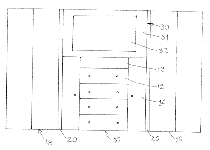
Figure 1 shows a first embodiment of'a modular furniture assembly according to
the present invention, which includes a base module 10 and left and right
modules 18, 19. A
pair of lifting columns 20 flanks the tease module 10, and a mounting panel 30
is mounted to
S and between the lifting columns 20 to enable vertical movement thereof. The
left and right
modules 18, 19 flank respective columns 20. The base module 10, as shown,
includes drawers
12, an appliance space I3 for a VCR, DVD, a stereo receiver and the like above
the drawers,
and cabinets 14 flanking the drawers. The module 10 may have any desired
arrangement of
shelves, drawers and cabinets. Likewise the left and right modules 18, 19 may
have any
IO desired arrangement of shelves, drawers and cabinets for books, records,
speakers, appliances,
or anything else.
The mounting panel 30 has a front surface 31 which carries a flat screen 32,
commonly referred to as a flat panel TV. Such a screen utilizes the same
signals as a CRT to
generate an image and accordingly may be used as a TV screen or a computer
monitor. When
15 it is used as a TV screen the signals can be provided by an antenna,
satellite receiver andlor
cable, a VCR, or a DVD player. When it is used as a computer monitor, the
signals can be
provided from the Internet, a CD, or a floppy disk. The mounting panel 30 is
shown in its
raised position where it conceals an upper module I7 (Figures 2, 6A, 6C) which
is mounted
aver the base module 10. When lowered, the mounting panel 30 will cover at
least a portion
20 of the base module 10 and provide access to the upper module. 'fhe screen
may be active, I.e.
turned ON, in any vertical position along its range of travel.
CA 02444368 2003-10-03
E3y Express Mail # Ev160129268US
Figure 2 is a top plan view of the assembly of Figure l, showing the top
module
I7, the lifting columns 20, the mounting panel 30 with the screen 32, and
spacers 38 inserted
between the panel 30 and the screen 32 to allow for ventilation and cooling of
the electronics in
the screen. Spacers 28 are provided between the base module and the end
modules 18, 19 to
accurately and securely position the various modules relative to each other,
and may be fixed
to the base module andlor top module and/or end modules by any type of
connector commonly
provided on furniture intended for assembly and disassembly in thE; home, e.g.
quarter turn
connectors. The positions of the connectors on the components are standardized
so that the
consumer may choose from a number of modules, as desired, available in the
retail store.
Each column 20 is secured to the base module 10 by means t)f an angle bracket
37, and the
mounting panel 30 is secured to the columns 20 by means of vertically oriented
angle brackets
34.
Figure 3 shows the column 20 and the brackets 34 and 37 in greater detail. The
column 20 includes a tubular housing 22 having a substantially rectangular
profile with a slot
23 in one wall where a vertically movable block 24 which can be accessed for
securing the
bracket 34. The bracket 34 is secclred to the block 24 by means of bolts 26
received through
holes in the outside leg 36 and thre<~ded into nuts fixed in the block 24.
Spacers in the form of
spools 27 are received through the slots 23 between the bracket 34 and the
block 24. The
bracket 34 is fixed to the mounting panel by bolts or machine screws received
through holes in
the inside leg 35. The leg 35 is considerably longer than the leg 36, because
it must be
11
CA 02444368 2003-10-03
I3y Express Mail ~t EV I60129268US
screwed to the wooden mounting panel 30. Likewise the bracket 37 has a longer
leg for
securing to the base than the leg which is secured to the lifting column 30.
The lifting columns 30 are manufactured by the German company K + B
Ergonomietechnik and are commercially available from (iros;~ Stabil
Corporation in
S Coldwater, Michigan. The Model T Mi 240 lifting column can be provided with
a height
which is especially suitable for the furniture assembly of the present
invention, in particular for
raising and lowering the mounting panel carrying a screen. Briefly, the
lifting columns operate
by rotating a threaded shaft 25 mounted vertically in each tube 22, the blocks
24 having thread-
engaging means which cause the blocks to move up and down synchronously as the
shafts are
rotated by electric motors.
Figure 4A shows the mounting panel 30 in the raised position, the brackets 34
being fixed to the rear surface 33 of panel 30 and being moved by blocks 24
traveling within
the lifting columns 20, as previously explained. A harness 40 of a plurality
of wires 54 is
secured to the rear surface 33 by a clamp 44 and is received througlh arl
aperture (not shown)
in the panel 30. The exterior of harness 40 is a sheath, preferably a plastic
sheath, and it
preferably contains a sufficient number of wires to accommodate all signal
sources that could
possibly be used to feed signals to the screen 32. These wires are connected
at one end to the
signal sources (unused wires just hang Loose) and at the other end these wires
are connected to
the screen 32 for providing signals and power to generate an image.
The electronics for image generation are provided in the screen assembly by
the
manufacturer of the screen assembly. The harness 40 is fed around and over a
front roller 46
12
CA 02444368 2003-10-03
F3y Express Mail # F:V I 60129268US
fixed to the top surface i5 of the base module 10, through the space 29
between the base
module 10 and the top module 17, and over a rear roller 48. Each of the
rollers 46; 48 is
~ournaled between a pair of supports and turns freely. The harness 40 has a
clamp 50 attached
securely thereto. Clamp 50 is movable along with harness 40 with respect to
the rear surface
16 of the base module 10. Referring also to Figure 4B, this clamp 50 is loaded
downward by
a pair of elastic tethers 52 which are each fixed at one end to the clamp 50
and at the other end
to an eye bolt 53 or the like to the bottom of the rear surface 16 of the base
module 10. The
tethers are under low tension in this view as the harness 40 is fully
retracted across the rear
surface 16 of the base module. Below the movable clamp 50, the exterior sheath
is removed
from the harness 40 to expose wires 54 which are connected to connector blocks
56 that serve
as inputs from, e.g., a TV antenna, a cable box, a satellite box, a DVD, a
VCR, and a PC.
Since the harness 40 is fully retracted, the individual wires are free to curl
as a result of slack
below clamp 50. This is acceptable because at this position the wires are out
of sight and
cannot get caught between any moving parts. However, harness 40 remains taut
above the
clamp 50 so that it cannot become damaged during motion of the mounting panel.
Figure 5A shows the mounting panel 30 in the lower position. As the panel 30
is lowered to this position by the action of the lifting columns 30, the
harness 40 is drawn over
the rollers 46 and 48. Referring also to Figure 5B, the elastic tethers 52 are
stretched to keep
the harness 40 under some tension, so that it remains in place on the rollers,
which may be
further assisted by profiling the rollers. 'The individual wires 54 straighten
out to the position
shown as the slack is reduced. However, they should not be under tension as
this might stress
I3
CA 02444368 2003-10-03
I3y Express Mail # EV160129268US
the connections at connectors 56. Note that a retraction mechanism other than
the elastic
tethers may be used, e.g. a spring of a type having appropriate
characteristics, or a weight
fixed to the clamp 50.
It should also be noted that the space 29 between the base module 15 and the
upper module 17 is not exposed, regardless of the position of the screen 32,
insofar as this
would be unsightly, and further would present the possibility of someone's
fingers or hands
being pinched in the rollers or caught between the mounting panel and the
modules as it
moves. However there are also safety features provided which will stop alI
motion in the event
that resistance is encountered, as will be described below.
Figure 6A is a schematic elevation of the base module 10 and the top module 17
without the end modules, and without the mounting panel attached to the
lifting columns 20.
The top surface 15 of the base module and the bottom of the top module 17 form
the space 29
containing rollers 46, 48, shown in Figures 4A and SA. The top module 17 is
shown having
shelves, but may be constructed with cabinets or other features. The modules
10, 17 can be
formed as a single unit, but forming fhem separately allows the consumer to
select from a
range of combinations. Figure 6~ shows the mounting panel 30 carrying the flat
screen 32 in
the raised position, where it covers the top module, and Figure 6C shows the
panel 30 in the
lowered position, where the top module 17 is exposed for access.
Figure 7A shows an alternative base module 60, designed as a computer work
station, having a desk surface 62, with drawers 63 and leg space below,
shelves 64 above, a
retractable keyboard leaf 66, and a computer monitor 67. This base module 60
is tlne same
14
CA 02444368 2003-10-03
Eiy Express Mail # EV160129268tJS
height as the base module 10 of the first embodiment, and so can take the same
top module 17
as shown. The end modules are not shown, but could be chosen as open shelves
for
peripherals such as a printer, scanner, disk storage, etc. Figure 6B shows the
panel 30 in the
raised position, which allows access to the work station 60. Figure 6C shows
the panel 30 in
the lower position, where the top module is exposed for access. The
arrangement of Figures
7A-7C permits an apartment dweller having limited space to cover the computer
work station
and to have the screen 32 at a comfortable viewing height in a living room.
Also, this
arrangement affords the user with a greater degree of flexibility in that
various activities, such
as surfing the Internet, can be done from a touch, with an infrared keyboard
and activating the
flat screen 30 rather than being confined to using the monitor 67 and sitting
at the desk. It is
also possible to simultaneously utilize both the flat screen 30 and the
monitor 37 for different
purposes.
Figure 8 depicts an arrangement that makes it possible to mount a flat screen
in
a corner of the room. Such screens are commonly mounted on a wall. However,
where wall
I S space is at a premium, it has been difficult to accommodate the flat
screens, particularly in
view of their large size. Corner space is usually more readily available than
wall space.
However, it has heretofore not been possible to mount the flat screens in a
corner since they
require a flat mounting surface.
In accordance with the invention, a base module 70 is provided which is
designed to fit in a corner of a room by being shaped substantially as a right
triangle. The
conventional shape of a piece of furniture designed to fit in a corner is
modified to have
CA 02444368 2003-10-03
13y Express Mail # EV I b01292b8US
truncated side corners 72 shaped and sized for accommodating tl~te lifting
columns 20 for
attachment thereto. Also, the rear corner 74 is truncated to form a space in
the corner of the
room to enable mounting the tethers 52 and connectors 56, as shown in Figures
4B and SB.
Fig. 9 is a schematic block diagram of a control circuit used for adjusting
the
vertical position of the mounting panel. A dedicated remote control 80 of the
conventional
kind, but generating a signal differf:nt from that used to control the T~
(e.g. volume, channels)
emits a position control signal 82 when its buttons (not shown) are pressed by
the user.
Alternatively, the remote control for the mounting panel can be combined into
a remote control
for the TV in a manner that is readily apparent to anyone with ordinary skill
in the art.
Position control signal detector 84 detects signal 82, processes it as
explained
below in connection with Fig. 10, and outputs control signal 86 to motor
control circuit 88
which controls reversible motor 90. Motor 90 powers the lifting columns, as
described above.
Safety detectors 92 are provided to detect when a person's hand, for example,
is
in a position which would result in injury if the mounting panel were to move
in accordance
with a command received from remote control 80. Preferably, detector 92 is a
bar (not shown)
that extends along the entire top of mounting panel 30. Another such bar can
be installed
along the bottom of the panel 30. '~ he bar is mounted to the panel 30 with
micro-switches that
open when the bar is deflected from its normal position. Thus, if a person is
standing with his
hand on the top of the mounting panel, this would deflect the bar sufficiently
to open a micro-
switch and generate a motion inhibit signal 94 to the motor control circuit
88. Thus, motion of
the mounting panel 30 is blocked until the inhibit signal is ended.
16
CA 02444368 2003-10-03
By Express Mail # EV 160129268US
Sensor 96 is provide°d to detect when the screen 32 is turned OFF.
When the
OFF mode is detected, a home position control signal 98 is inputted to motor
control circuit 88
which, in turn, positions the mounting panel 30 in its upper-mast position. It
is presumed that
when the screen 32 is OFF, it is left unattended. I3y automatically raising
the mounting panel
30, the invention provides a safeguard against someone inadvertently colliding
with the screen
in the dark or accidentally banging against it with something. It is also a
safer position with
children in the house.
Fig. 10 depicts the operations carried out by the combination of position
signal
detector 84 and motor control ci1-cuit 88. Per operation 100, the system
checks at preset
intervals controlled by a high frequency clock whether a signal has been
received from remote
control 80. If such a signal has been received, step 102 determines whether it
is an UP motion
command. If it is, then step I04 checks whether the safety detector has been
activated. If it
has, then motion is inhibited, per 106. If the safety detector has not been
activated, then step
I08 raises the mounting panel 30 for as long as a signal is being received
from the remote
control.
If step 102 determines that the received signal is not an UP signal, it is
presumed that the signal is a DOWN signal. Step IIO is similar to step 104 in
checking
whether the safety detector 92 is activated. If it is, then motion is
inhibited by step II2.
Otherwise, step I14 lowers the mounting panel 30 for as long as a signal is
being received
from the remote control.
17
CA 02444368 2003-10-03
By Express Mail # EV160129268US
If step 100 determines that no signal is being received from the remote
control,
step 116 checks whether the screen is ON. If it is, then the flow of steps
returns to step 100. If
the screen is OFF, step 118, which is similar to step 104, checks whether the
safety detector
92 is activated. If it is, then motion is inhibited by step 120. Otherwise,
the mounting panel is
S raised to a preset "home" position, per step 122, which typically would be
the uppermost
position reachable by the lifting mechanism.
Although a preferred embodiment of the present invention has been described in
detail above, various modifications thereto will be readily apparent to anyone
with ordinary
skill in the art. For example, the lifting columns need not be located toward
the front of the
base, but may be located further back and out of sight, being connected to the
mounting panel
by larger brackets than those shown in the drawings. It is also possible for
the lifting
mechanisms to be pneumatically powered. All such modifications are intended to
fall within
the scope of the present invention.
Thus, while there have shown and described and pointed out fundamental novel
1S features of the invention as applied to a preferred embodiment thereof, it
will be understood
that various omissions and substitutions and changes in the form and details
of tlae devices
illustrated, and in their operation, may be made by those skilled in the art
without departing
from the spirit of the invention. For example, it is expressly intended that
all combinations of
those elements and/or method steps which perform substantially the same
function in
substantially the same way to achieve the same results are within the scope of
the invention.
Moreover, it should be recognized that structures and/or elements and/or
method steps shown
18
CA 02444368 2003-10-03
By Express Mail # EV160129268US
and/or described in connection with any disclosed form or embodiment of the
invention may be
incorporated in any other disclosed or described or suggested form or
embodiment as a general
matter of design choice. It is the intention, therefore, to be limited only as
indicated by the
scope of the claims appended hereto.
19