Note: Descriptions are shown in the official language in which they were submitted.
CA 02444523 2003-10-09
SPECIFICATION
TITLE OF THE INVENTION
FUEL CELL AND PROCESS FOR THE PRODUCTION OF SAME
BACKGR0~7ND OF THE I NTION
Field of the Invention
The present invention relates to a normally operating fuel
cell for use in portable power supply, powE:r supply for electric
car, household cogeneration system, etc. and a process for the
production thereof.
Related Art of the Inventa.on
The basic structure of the related art polymer electrolyte
type fuel cell will be described in connection with Fig. 7.
Fig. 7 is a longitudinal sectional view illustrating the
configuration of the related art polymer electrolyte type fuel
cell stack.
A solid polymer electrolyte type fuel cell allows a fuel
gas containing hydrogen and an oxidizer gas containing oxygen
such as air to undergo electrochemical reaction to generate
electricity and heat at the same time.
Referring to general structure, the solid polymer
electrolyte type fuel cell comprises a polymer electrolyte
membrane 1 which allows selective transportation of hydrogen
1
CA 02444523 2003-10-09
ion upon the application of an electric field and a pair of gas
diffusion electrodes 2 formed on the respective sides thereof .
The gas diffusion electrode 2 is mainly composed of a carbon
powder having a platinum group metal catalyst supported thereon
and comprises a catalyst layer formed s_n contact with the polymer
electrolyte membrane 1 and a gas diffusion layer having air
permeability and electronic conductivity in combination formed
on the separator 3 side.
Further, the gas diffusion electrode 2 has a gasket 4 (or
gas sealing material) disposedaroundthe g<~s diffusion electrode
2 to prevent the two gases supplied from leaking or being mixed
with each other.
The gasket 4 may have been previously assembled integrally
with the gas diffusion electrode 2 and the polymer electrolyte
membrane 1.
The configuration comprising the polymer electrolyte
membrane 1 and the catalyst layer is referred to as "MEA
(membrane-electrode assembly)°°.
In an ordinary polymer electrolyte type fuel cell, MEA is
mechanically fixed and an electrically-conductive separator 3
for electrically connecting adj acent MEAs t;o each other in series
indisposed. The laminationofanumberofsi:nglecellsessentially
comprising MEA and electrically-conductive separator3 produces
a fuel cell stack.
The separator 3 is made of an electrz.cally-conductive and
2
CA 02444523 2003-10-09
airtight material having some corrosion re:~istance such as carbon
plate and metal plate. In each of the single cells, a gas channel
for supplying the reactive gas onto the surface of the electrode
and removing the produced gas or extra gas is formed on the portion
in contact with MEA of the separator 3.
The gas channel may be provided on t:he portion other than
separator 3 such as the surface of the gas diffusion electrode.
However, it is usual that a groove is provided on the surface
of the separator 3 to form a gas channel.
In order to supply the reactive gas through the groove,
a means is required of supplying and distributing the reactive
gas into the respective single cells and collectingthe gas produced
inthegasdiffusionelectrode2andtheresidualgasanddischarging
these gases to the exterior of the cell"
The hole which is formed through the respective single cells
to supply the fuel gas and oxidizer gas into the respective single
cells and discharge these gases is referred to as '°manifold".
Manifolds are divided into two types, i.e., internal
manifold type which is a series of through-holes formed by
laminating separators 3 each having a through-hole formed therein
in the direction of stack and external manifold type formed on
the side of a laminate of separators 3 as a structure other than
the separator 3.
A fuel cell generates heat during operation and thus is
required to be cooled with cooling water or the like to keep
3
CA 02444523 2003-10-09
itself under good temperature conditions.
In general, a cooling portion which. allows cooling water
to flow every 1 to 3 cells is provided interposed between the
separators 3. In most cases, a cooling water channel is provided
on the back of the separator 3 to form a cooling portion. The
supply of cooling water into the cooling portions and discharge
of cooling water therefrom are conducted through the manifold
formed through the respective cells as in the case of supply
and discharge of the reactive gas.
An ordinary cell stack is obtained by laminating MEAs,
separators 3 and cooling portions on each ot=her to form a laminate
of from 10 to 200 cells, clamping the stack between end plates
with a collector and an insulating plate interposed therebetween,
and then fixing the stack with a clamping bolt from both ends
thereof.
As the fuel for polymer electrolyte type fuel cell there
is used hydrogen. Hydrogen may be supplied from a hydrogen bottle
or may be obtained by converting a hydrocarbon fuel to hydrogen
through a modifier. As the oxidizer gas there may be used air.
Since the polymer electrolyte membrane 1 can be provided
with a high hydrogen ionic conductivity only when it is hydrous,
either the fuel gas or air to be supplied into the fuel cell
is often provided with water vapor. For the supply of such a
reactive gas into the fuel cell, a blower or compressor is used.
The electric power produced by the fuel cell is DC power,
4
CA 02444523 2003-10-09
which is better used at a higher voltage to give a higher utility.
Accordingly, DC power is converted to AC power having a higher
voltage by a converter or inverter.
The electrochemical reaction of hydrogen with oxygen and
the resulting generation of electric current are accompanied
by the generation of heat . In order to keep the cell temperature
constant, the heat thus generated is released to the exterior
of the cell or the cell is cooled with a heat medium. The heat
which has been withdrawn to the exterior: of the fuel cell is
then utilized for hot water supply or heating in the household
cogeneration system.
A fuel cell system comprises this fuel cell and modifier,
a power management portion .such as convE:rter and inverter, a
heat utilization element and a control system for functionally
operating these portions.
Among the gas diffusion electrodes 2, th.e electrode into
which the fuel gas is supplied is referred to as "anode" while
the electrode into which the oxidizer gas such as air is supplied
isreferredto as"cathode". Duringthe generation of electricity,
the anode acts as a negative electrode while the cathode acts
as a positive electrode.
On the anode, hydrogen supplied is oxidized in the vicinity
of the catalyst to produce hydrogen ion which is then released
into the electrolyte. On the cathode, hydrogen ion supplied from
the anode and oxygen in the oxidizer gas react to produce water.
CA 02444523 2003-10-09
Accordingly, these gas diffusion elecarodes 2 must be highly
air-permeable throughout its entirety so that all the electrodes
can be thoroughly supplied with the reactive gas onto the surface
of the catalyst which is a reaction site and the resulting water
vapor and the unreacted carbonate gas, nitrogen, etc. can be
readily discharged from the reaction site.
Similarly, it is important that these gas diffusion
electrodes 2 each are arranged such that hydrogen ion and electron
can be easily supplied into the reaction site and discharged
from the reaction site.
The gas supplied has been moistened at a dew point close
to the cell temperature to enhance the hydrogen ionic conductivity
of the electrolyte. Therefore, when the gas is consumed at any
of the electrodes, supersaturated water vapor undergoes dew
condensation on the interior of the elects rodes.
The amount of water condensate is greater on the cathode
because it also contains water content produced by the reaction.
The water condensate thus formed is then reevaporated in
the gas supplied or discharged as water droplet along with the
discharged gas into the gas discharge manifold via the gas supply
passage.
AsthemethodofproducingMEA~membrane-electrodeassembly)
for polymer electrolyte type fuel cell there has heretofore been
normally employed a method which comprises forming a polymer
electrolyte membrane 1 according to an extrusion method,
6
CA 02444523 2004-11-18
subjecting the electrolyte membrane 1 to heat treatment, forming
a catalyst layer on both sides of the polymer electrolyte membrane
1 according to a printing method, transferring method or the
like, and then forming a gas diffusion layer made of carbon paper,
carbon cloth or the like on the outer side of the catalyst layer.
In recent years, it has been sometimes practiced to improve
the cell performance and reduce the production cost by using
a production method which comprises casting a polymer electrolyte
membrane 1 into a sheet with polymer electrolyte solution,
continuously forming an anode side catalyst layer and a cathode
side catalyst layer in front and in rear of the sheet, and then
subjecting the combination to heat treatment.
Further, in order to prevent the break of the polymer
electrolyte membrane 1, pores 21 of a porous material or fiber
22 shown in Figs. 9and10, etc. may be utilized (see JP-A-8-162132,
JP-A-8-213027, JP-A-8-329962, and JP-A-2001-345110). Fig. 9 is
alongitudinalsectionalview (first sectionalview) illustrating
a reinforcing structure for MEA for the related art polymer
electrolyte type fuel cell, and Fig . 10 is a longitudinal sectional
view (second sectional view) illustrating another reinforcing
structure for MEA for the related art polymer electrolyte type
fuel cell.
7
CA 02444523 2003-10-09
In general, a perfluorocarbonsulfonic acid to be used as
a polymer electrolyte is formed by a main chain moiety for securing
thermal and electrochemical stability and mechanical strength
and a pendant moiety which takes part in ionic conduction. It
is said that when the perfluorocarbonsulfonic acid actually acts
as an electrolyte, the pendant moieties gather together to cause
hydration of water molecules that forms an ionic conduction
channel.
Further, in order to keep the ionic conductivity of the
polymer electrolyte high, it is necessary that the gas supplied
be moistened to keep the polymer electrolyte highly hydrous.
In general, such a polymer electrolyte has properties as
viscoelastic material. In other words, when a predetermined
tension (or compressive force) is kept applied to the electrolyte
membrane, the initial elastic defcrmation is followed by plastic
deformation, i.e., so-called creep. On the contrary, when a
tension (or compressive force) causing a predetermined
deformation is kept applied to the electrolyte membrane, the
electrolyte membrane undergoes relaxation and reduction tension
(or compressive force) with time, i.e., so-called stress
relaxation.
A polymer electrolyte type fuel cell comprises a stack of
basic configurations each comprising a polymer electrolyte
membrane 1, gas diffusion electrodes 2 with the polymer electrolyte
membrane 1 interposed therebetween and a separator 3, clamped
8
CA 02444523 2003-10-09
at a predetermined pressure on both end: thereof as shown in
Fig. 7. Accordingly, a predetermined compressive pressure 5 is
always applied to these constituents.
When a compressive pressure acts on the polymer electrolyte
membrane 1 from the separator 3 via the catalyst layer and the
gas diffusion layer over an extended period of time, the polymer
electrolyte membrane 1 undergoes plastic: deformation.
The catalyst layer and the gas dif:Eusion layer each are
essentially a porous material and have a complicated surface.
As a result, part of the polymer electrolyte membrane 1
which has undergone plastic deformation penetrates the interior
of the catalyst layer or the gas diffusion layer in the part
having a relatively low density or small. mechanical strength
as shown in Fig. 8. Fig. 8 is a longitudinal sectional view
illustrating the cell in the related art. polymer electrolyte
type fuel cell stack after a prolonged operation.
Further, when creep proceeds, the reactive gas on the anode
side and the cathode side are eventually mixed with each other
to cause cross leak or the anode and the cathode make an electrical
contact with each other to cause minute shortcircuiting as
indicated by the sign x in Fig. 8.
The aforementioned cross leak or minute shortcircuiting
not only causes the deterioration of cell performance by itself
but also gives a new cause of performance deterioration due to
local heat generation or drying or shortage of reactive gas.
9
CA 02444523 2004-11-18
The clamping pressure applied to the stack from both ends
thereof is supported by the gasket 4 or sealing material arranged
around MEA. At this point, the contact pressure applied by the
separator 3 to the electrolyte membrane via the gas diffusion
electrode 2 reaches a predetermined value. Then, the polymer
electrolyte membrane 1 which is a viscoelastic material undergoes
stress relaxation. Thus, the contact pressure decreases with
time.
When the contact pressure across the catalyst layer and
the gas diffusion layer and across the gas diffusion layer and
the separator as shown by the sign y in Fig. 8 decrease, the
contact resistance of electronic conduction increases, causing
the rise of electricity generation loss at these sites. As a
result, the cell performance is deteriorated.
An aim of the invention is to provide a fuel cell which
is little subj ect to deterioration of performance and destruction
caused by creep or stress relaxation phenomenon in the electrolyte
and a process for the production thereof taking into account
the aforementioned problems with the related art.
SUMMARY OF THE INVENTION
The lsr aspect of the present invention is a unit cell for
use in an electrolyte membrane-electrode assembly in which a
plurality of unit cells are held in fuel cell stack arrangement
by clamping pressure, wherein an electrolyte member of the unit
CA 02444523 2004-11-18
cell comprises at least one support member incorporated therein
for counteracting the clamping pressure, the support member
exhibiting a greatercreep resistancethanthe electrolyte member.
The 2nd aspect of the present invention is the fuel cell
as defined in the 1St aspect of the present invention, wherein
the support member is a granular member .
The 3rd aspect of the present invention is the fuel cell
as defined in the 2nd aspect of the present invention, wherein
the diameter of the granular member is less than the thickness
of the electrolyte membrane.
The 4th aspect of the present invention is the fuel cell
as deffined in the 2nd aspect of the present invention, wherein
an average diameter of the granular member is 5 ~m or greater.
The 5th aspect of the present invention is the fuel cell
as defined in any of the previous aspects of the present invention,
wherein the material constituting the support member is titanium,
metal oxide, metal nitride, inorganic glass or fluororesin.
The 6th aspect of the present invention is the fuel cell
as def fined in any of the previous aspects of the present invention,
wherein the support member comprises a polymer having a structure
in which a main chain moiety is the same as that of the material
constituting the electrolyte membrane.
The 7th aspect of the present invention is a unit cell
producing method, the unit cell being for use in an electrolyte
membrane-electrode assembly in which a plurality of unit cells
11
CA 02444523 2004-11-18
are held in a fuel cell stack arrangement by a clamping pressure,
which method comprises : incorporating at lest one support member
in the electrolyte membrane of the unit cell to counteract the
clamping pressure, wherein the support member has a greater creep
resistance than the electrolyte membrane.
The support member may also sometimes be referred to as
the predetermined member.
Brief Description of the Drawings
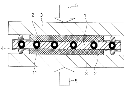
Fig. 1 is a schematic longitudinal sectional view
illustrating the configuration of MEA for solid polymer
electrolyte type fuel cell according to the Embodiment 1 for
carrying out the invention;
Fig. 2 is a schematic longitudinal sectional view
illustrating the configuration of MEA for solid polymer
electrolyte type fuel cell according to the Embodiment 1
implementation of the invention;
Fig. 3 is a partly enlarged diagram of MEA for solid polymer
electrolyte type fuel cell according to the Embodiment 1 of
implementation of the invention;
Fig. 4 is a longitudinal sectional view illustrating the
configuration of MEA for solid polymer electrolyte type fuel
cell according to the Embodiment 1 of implementation of the
12
CA 02444523 2003-10-09
lnVentlOn;
Fig. 5 is a schematic diagram illustrating the configuration
of a device used in the evaluation of the creep resistance of
the materials to be incorporated in the electrolyte membrane
according to an embodiment of implementation of the invention;
Fig. 6(a) is a diagram (first diagram) illustrating the
creep resistance of a material (polyvinyl-based resin) to be
incorporated in the electrolyte membrane;
Fig. 6(b) is a diagram (second diagram) illustrating the
creep resistance of another material (perfluorocarbonsulfonic
acid) to be incorporated in the electrolyte membrane;
Fig. 6(c) is a diagram (third diagram) illustrating the
creep resistance of a further material (PT:E~E) to be incorporated
in the electrolyte membrane;
Fig. 7 is a longitudinal sectional view illustrating the
configuration of the related art polymer electrolyte type fuel
cell stack;
Fig. 8 is a longitudinal sectional view illustrating the
cell in the related art polymer electrolyte type fuel cell after
a prolonged operation;
Fig. 9 is a longitudinal sectional view (first sectional
view) illustrating a reinforcing structure for MEA for the related
art polymer electrolyte type fuel cell; and
Fig. 10 is a longitudinal sectional view (second sectional
view) illustrating another reinforcing :>tructure for MEA for
23
CA 02444523 2003-10-09
the related art polymer electrolyte type fuel cell.
Description of Reference Numerals
1 Polymer electrolyte membrane
2 Gas diffusion electrode
3 Separator
4 Gasket
Clamping force (compressive pressure)
11, 12, 13 Beads to be incorporated
Supporting force against clamping force
PREFERRED EMEODIMENTS OF THE INVENTION
Embodiments of implementation of the invention will be
described hereinafter in connection with t:he attached drawings.
(Embodiment 1)
Firstly, the configuration of a polymer electrolyte type
fuel cell according to the present mode for carrying out the
invention will be described in connection mainly with Fig. 1.
Fig. 1 is a schematic longitudinal sectional view illustrating
the configuration of MEA for solid polymer electrolyte type fuel
cell according to the present mode for carrying out the invention.
The polymer electrolyte type fuel cell according to the
present mode for carrying out the invention comprises a cell
stack comprising a membrane-electrode assembly composed of a
polymer electrolyte membrane 1 and a pair of gas diffusion
14
CA 02444523 2003-10-09
electrodes 2 having the polymer electrolyte membrane 1 interposed
therebetween and separators 3 laminated alternately on the
membrane-electrode assembly wherein a clamping pressure is
applied to the cell stack.
The polymer electrolyte type fuel cell according to the
present mode for carrying out the invention is characterized
by the arrangement that the polymer electrolyte membrane 1 has
beads 11 having a greater creep resistance than the electrolyte
membrane incorporated therein across the electrolyte membrane
and the beads 11 support the clamping pressure on the cell stack.
The beads 11 each preferably have a particle diameter of
greater than 5 ~.m on the average and not greater than the thickness
of the polymer electrolyte membrane 1. Further, the beads 11
each preferably are made of a material selected from the group
consisting of titanium, metal oxide, metal nitride, inorganic
glass material and fluororesin. Moreover, the beads 11 each
preferably are made of a polymer electrolyte material different
from the material constituting the electrolyte membrane.
A detailed configuration of_ the polymer electrolyte type
fuel cell according to the present mode for carrying out the
invention will be described hereinafter.
The polymer electrolyte membrane 1 is a hydrous
fluorine-based or hydrocarbon-based membrane having a thickness
of from 15 ~.m. to 200 ~.m which is more subject to creep against
stress as the ambient temperature is higher or the coexisting
CA 02444523 2003-10-09
humidifying gas has a high relative humidity.
In order toformtheelectrolytemembra.nebyasinglematerial
so that the deterioration of performance or destruction of fuel
cell due to creep can be prevented, it is necessary that the
creep resistance of the material itself be enhanced.
However, if it is desired to keep the hydrogen ionic
conductivity high, the improvement of the material is limited.
Therefore, in order to enhance the creep resistance of the
entire electrolyte membrane while maintaining the desired
hydrogen ionic conductivity, the material of the electrolyte
membrane comprises beads of a material having a higher rigidity
and a high creep resistance such as zirconia, glass and fluororesin
incorporated therein in addition to a material taking part mainly
in hydrogen ionic conductivity.
These beads are arranged as shown in Fig. 1 or 2 to support
the compression 5 applied to the electrolyte membrane via a gas
diffusion layer or catalyst layer. Fig. 2 is a schematic
longitudinal sectional view illustrating the configuration of
MEA for solid polymer electrolyte type fuel cell according to
the present mode for carrying out the invention.
In Fig. 1, the beads 11 having a high creep resistance and
aparticle diameterwhichissubstantiallythesame asthethickness
of the electrolyte membrane incorporated in the electrolyte
membrane 1 support the compression.
In Fig. 2, the beads 12 having a high creep resistance
26
CA 02444523 2003-10-09
incorporated in the electrolyte membrane 1 come in contact with
each other to form a supporting force 15 against the clamping
force applied to the electrolyte membrane as shown in Fig. 3.
Fig. 3 is a partly enlarged diagram of MEA for solid polymer
electrolyte type fuel cell according to the present mode for
carrying out the invention (enlarged diagram of the portion III
of Fig. 2).
It goes without saying that even the beads 13 incorporated
in the electrolyte membrane don't come in direct contact with
each other as shown in Fig. 4, the creep resistance of the mixed
material is enhanced. Fig. 4 is a longitudinal sectional view
illustrating the configuration of MEA for solid polymer
electrolyte type fuel cell according to the present mode for
carrying out the invention.
Pores 21 and fibers 22 of a porous material having a
reinforcing capacity for preventing the break of the polymer
electrolyte membrane 1 shown in Fig. 9 or 10 which have heretofore
been used are essentially different from the beads according
to the present mode for carrying out the invention.
In other words, in Figs. 9 and l0, the pores 21 and the
fibers 22 are provided to act to prevent the break of portions
at which a shearing force or tension acts on the polymer electrolyte
membrane 1 such as edge of the gas diffusion electrode 2.
Accordingly, it is important that the pores 21 are formed
continuously in the direction along the surface of the electrolyte
17
CA 02444523 2003-10-09
membrane as shown in Fig. 9 or the fibers ~2 are formed overlapping
each other as shown in Fig. 10.
On the contrary, in the present mode for carrying out the
invention, the beads 13 are preferably formed continuously in
the direction perpendicular to the surfa<:e of the electrolyte
membrane or overlapping each other.
Thus, the configuration of the present mode for carrying
out the invention is essentially different from that of the related
art.
Referring to the material to be incorporated in the
electrolyte membrane 1, tensile strength or shear strength is
necessary in the configuration of the related art shown in Figs .
9 and 10 whi 1 a compres s ive st rength or creep res i stance i s important
in the invention.
The gas diffusion electrode 2 corresponds to the electrode
of the invention, the polymer electrolyte membrane 1 corresponds
to the electrolyte membrane of the invention, and the beads 11
to 13 each correspond to the predetermined member of the invention .
The fuel cell of the invention and the process for the
production thereof will be further described hereinafter in
connection with the attached drawings.
(Example 1 )
Firstly, Ketj en Black EC (produced by AKZO Chemie Inc. of
Holland), which is a particulate electrically-conductive carbon
having an average primary particle diameter of 30 nm, having
18
CA 02444523 2003-10-09
50 wt- o particular platinum having an average particle diameter
of about 30 angstrom supported thereupon was used as
particle-supported catalyst for cathode. On the other hand,
Ketjen Black EC having particulate platinum and particulate
ruthenium having an average particle diameter of about 30 angstrom
supported thereon in an amount of 25 o by weight, respectively,
was used as particle-supported catalyst for anode.
Subsequently, these carbon powders having a catalyst metal
such as platinum supported thereupon were each dispersed in an
alcohol solution of polymer electrolyte to make a slurry.
The alcohol solution of polymer electrolyte used was
obtained by dispersing 16 wt- o perfluorocarbonsulfonic acid in
ethyl alcohol (Flemion, produced by ASAHI GLASS COMPANY).
On the other hand, a carbon paper having a thickness of
400 Nmwhich acts as an electrode was dipped in an aqueous dispersion
of fluororesin (NeoflonNDl, produced byDaikin Industries, Ltd. ) ,
dried, and then subj ected to heat treatment at 400°C for 30 minutes
to render itself water-repellent.
Subsequently,theaforementionedslurrycontaininga carbon
powder was uniformly spread over one side of the aforementioned
carbon paper thus rendered water-repellent to form a catalyst
layer thereon. Thus, a gas diffusion electrode was prepared.
The size of the electrode was 6 cm x 6 cm.
The polymer electrolyte membrane was obtained by
cast-molding the aforementioned polymer electrolyte solution
19
CA 02444523 2003-10-09
into a sheet, drying the sheet, and then subjecting the sheet
to heat treatment.
In other words, a solution comprising water containing 10
wt- o of a polymer electrolyte and ethyl alcohol as mixed solvent
was concentrated by vacuum suction or the like to obtain a 16
wt-o high concentration solution. The high concentration
solution wasthen mixed with polytetrafluoroethylene(PTFE)beads
having an average particle diameter of 30 ~tm in an amount of
2 wt-% based on the total weight of the solution. The mixture
was then stirred thoroughly.
The aforementioned PTFE bead-incorporated electrolyte
solution was spread over a polyethylene terephthalate (PET) film
coated with a fluorine-based release agent using a bar coater,
and then dried.
By adjusting the number of spreading or the concentration
of the coating solution, the thickness of the polymer electrolyte
membrane dried was adjusted to 50 ~m ~ 5 p.zm.
The electrolyte membrane thus produced was cut into a size
of 12 cm square which was then subjected to heat treatment at
a temperature of 130°C for 30 to 60 minutes in a heat treatment
device filled with nitrogen gas.
Two sheets of the carbon paper having a catalyst layer formed
thereon were then laminated on each other with the catalyst layer
side thereof disposed opposed to each other and the solid polymer
electrolyte membrane disposed interposed therebetween.
CA 02444523 2003-10-09
In order to prevent the gases suppliecL from leaking or being
mixed with each other, a sheet (gasket) made of silicone rubber
having a thickness of about 350 ~m for gas seal was provided
on the periphery of the electrode with the polymer electrolyte
membrane disposedinterposedtherebetween. Thelaminatewasthen
hot-pressed at a temperature of 100°C for. 5 minutes to obtain
MEA.
Two sheets of carbon separator having a gas channel formed
on the surface of sintered carbon plate by cutting were arranged
suchthatthegaschannelwasopposedtotheelectrode. Thelaminate
was then clamped by a clamping pressure of 5 kgwt/cm2 applied
thereto via a stainless steel end plate.
The fuel cell thus produced was then subj ected to evaluation
test using pure hydrogen and air as reactive gas under the following
conditions.
The evaluationtest wasconducted understandard condition
I that the temperature of the cell is 75°C, the dew point of pure
hydrogen gas supplied onto the anode is 70°C, the dew point of
air supplied onto the cathode is 70°C, the percent utilization
of hydrogen is 750, the percent utilization of air is 40o and
the current density is 0.2 A/cmz.
The evaluation test was also conducted under accelerated
condition II that accelerates more the creep in the electrolyte
and the catalyst layer. This accelerated condition is the same
as the standard condition T except that the temperature of the
21
CA 02444523 2003-10-09
cell is 85°C, the dew point of hydrogen is E35°C and the dew
point
of air is 85°C.
A related art MEA having no second material such as PTFE
beads incorporated in the electrolyte was subjected to evaluation
test under both conditions for reference.
These MEAs and operating conditions were combined to give
four test conditions. 10 cells (N = 10) were tested for each
of the four combinations . The cell evaluation test was conducted
for 2,000 hours. The results are set forth in Table 1.
Table 1
Standard condition Accelerated condition
I I!
Number of cells DeteriorationNumber of cells Deterioration
which which
have been untestablerate (after have been untestablerate (after
2,000 2,000
up to 2,000 hours hours of elapse)up to 2,000 hourshours of elapse)
(in a total of (in a total of
10 cells) 10 cells)
Example 0 0 ~ 2 mVI1000h1 4 mVI1000h
Comparative3 10 mV/1000h 5 80 mVl1OOOh
Example
Actually, some of the cells showed a. sudden deterioration
of performance that disabled the continuance of the durability
test during the evaluation test (cell destruction).
Further, even the cells which allowed the continuance of
the durability test showed a great difference in deterioration
rate depending on the configuration of MEA or testing conditions.
As can be seen in the results set forth in Table 1, MEA
of the present example is little subject to cell destruction
22
CA 02444523 2003-10-09
that disables the continuance of test as compared with MEA of
the related art . It was alsomade obvious that the cells comprising
MEA of the related art which had undergone destruction showed
cross leak of hydrogen gas as much as about 10 times that of
the cells which had undergone no destruction. It was further
made obvious that the cells which had undergone destruction showed
a DC resistance drop of about half that of the>se which had undergone
no destruction, demonstrating that it is much likely that the
creep of the electrolyte membrane caused the shortcircuiting
of the two electrodes.
Further, the comparison of the test results under the
standard condition I and the accelerated condition I I made obvious
that the probability of cell destruction is higher under the
accelerated condition II than under the standard condition I.
Accordingly, these results suggest that this cell destruction
is caused by the creep of the electrolyte membrane taking into
account the fact that the creep resistance of the electrolyte
membrane deteriorates under high tempE:rature and humidity
conditions.
It was thus made obvious that the use of MEA having an improved
membrane creep resistance makes it possible to inhibit the cell
destruction during continuous operation,.
It was also made obvious that the deterioration rate of
MEA of the invention is much lower than MEA of the related art
as set forth in Table 1, demonstrating that the use of MEA of
23
CA 02444523 2003-10-09
the invention makes it possible to inhibit the deterioration
of performance with the increase of contact resistance due to
stress relaxation.
(Example 2)
In the present example, the particle diameter and mixing
proportion of beads incorporated in the membrane were studied.
Beads of hard glass having different particle diameters
were prepared. For the preparation of beads having a particle
diameter of not greater than 20 Nxn, hard glass was ground by
a ball mill to adj ust the average particle diameter of the beads .
MEAs comprising glass beads having different particle diameters
incorporatedin polymer electrolyte membrane were thensubjected
to cell durability test in the same manner as in Example 1.
As a result, it was made obvious that when the particle
diameter of the beads incorporated in the membrane is as small
as not greater than 5 Vim, the resulting effect of inhibiting
the cell destruction or deterioration is small. On the contrary,
when the particle diameter of the beads is too great, the resulting
membrane solution cannot be tasted onto PET substrate to form
a film thereon or the resulting electrolyte membrane itself
exhibits a reduced mechanical strength to disadvantage.
The particle diameter of the beads to be incorporated in
the electrolyte membrane is preferably from greater than 5 ~m
to not greater than the thickness of the electrolyte membrane.
The mixing proportion of the bead;> was then studied.
24
CA 02444523 2003-10-09
It is thought that when a 16 wt-o solution of polymer
electrolyte (Flemion, produced by ASAHI c~LASS COMPANY) having
2 wt-o PTFE beads incorporated therein is carted to form a film,
PTFE beads account for about 100 of the volume of the polymer
electrolyte, though depending on the hydrous state of the polymer
electrolyte membrane.
PTFE beads having an average particle diameter of 30 ~m
were incorporated in a polymer electrolyte solution in an amount
of 0. 3 o, 1 o, 3 0, 10 0, 30 0, 50 o and 70 o by volume, respectively,
and the polymer electrolyte solutions were each then carted to
form a film in the same manner as in Example 1.
These MEAs were each then subjected to cell evaluation
durability test in the same manner as in Example 1. As a result,
it was confirmed that the cells comprising :MEAs .'having PTFE beads
incorporated therein in an amount of not smaller than 1 o by volume
have its advantage. In other words, those cells comprising
membranes having beads incorporated therein in such an amount
undergo destruction less frequently or show a lower deterioration
rate than those comprising the related art MEAs.
Thepolymerelectrolytesolutionshavingbeadsincorporated
therein in an amount of greater than 50 o byvolume canbe difficultly
carted to form a film.
This experiment was conducted with PTFE beads. However,
it is thought that glass beads or the like need to be incorporated
in an amount as much as twice to three times PTFE because of
CA 02444523 2003-10-09
their difference in specific gravity.
The mixing proportion of materials which has an effect on
the cell durability is probably affected greatly by the specific
gravity, shape, particle diameter (powder diameter), creep
resistance, etc. of the materials incorporated.
It is also thought that the mixing proportion of materials
depends greatly on the sealing structure or clamping structure
of cell stack taking into account the mechanism causing cell
destruction or the mechanism of performance: deterioration caused
by the increase of contact resistance due to the drop of contact
pressure.
(Example 3)
In the present example, the materials to be incorporated
in the electrolyte membrane were studied to inhibit the
deterioration of performance caused by 'the creep or stress
relaxation of the electrolyte membrane.
Firstly, the perfluorocarbonsulfonic acid, PTFE and
polyvinyl-based resin as used as electrolyte material in Example
1 were each cut into a strip having a thickness of 200 Vim, a
width of 10 mm and a length of 50 mm which was then measured
for creep properties according to the method shown in Fig. 5.
Fig. 5 is a schematic diagram illustrating the configuration
of a device used in the evaluation of the creep resistance of
the materials to be incorporated in the electrolyte membrane
according to an embodiment of implementation of the invention.
26
CA 02444523 2003-10-09
The device is arranged such that a ten.>ile 1 oad 34 is applied
to a specimen 30 fixed at an upper chuck 32 mounted on a base
31 and a lower chuck 33.
A predetermined tensile load 34 (100 to 500 gwt) was then
applied to the aforementioned three specimens at the both ends
thereof . The elapsed time and the length L of the specimen were
then measured.
During the measurement, the atmosphere was kept at a relative
humidity of 50 o so that moisture conditioning was kept constant.
As can be seen in Figs. 6(a) to 6(c), all the specimens
show an instantaneous deformation with the application of tensile
load but then gradually stretches with time . Fig. 6 ( a) is a diagram
(first diagram) illustrating the creep resistance of a material
(polyvinyl-based resin) to be incorporated in the electrolyte
membrane. Fig. 6 (b) is a diagram (second diagram) illustrating
thecreep resistanceof anothermaterial(perfluorocarbonsulfonic
acid) to be incorporated in the electrolyte membrane. Fig. 6 (c)
is a diagram (third diagram) illustrating the creep resistance
of a further material (PTFE) to be incorporated in the electrolyte
membrane.
As opposed to instantaneous deformation shortly after
pulling (elastic deformation), the elongation developed after
a predetermined period of time of elapse ( 1 to 5 hours ) following
the application of tensile load is defined to be creep deformation.
Among the specimens of perfluorocarbonsulfonic acid, PTFE
27
CA 02444523 2003-10-09
and polyvinyl-based resin used in the experiment, the specimen
of polyvinyl-based resin showed the greatest creep deformation.
The specimen of perfluarocarbonsulfonic acid showed the second
greatest creep deformation. The specimen of PTFE showed the
smallest creep deformation.
It can be said that the smaller the creep deformation is,
the greater is the creep resistance.
The aforementioned polyvinyl-based resin, too, was
incorporated in the electrolyte membrane in the form of beads
having an average particle diameter of 30 ~.rn in the same manner
as in Examples 1 and 2 to produce MEA.
However,MEAhavingthispolyvinyl-basedresinincorporated
therein could not be provided with a reduced probability or
deterioration rate that causes sudden cell destruction.
Further, the aforementioned MEA obviouslyshowed a greater
frequency of occurrence of cell destruction as compared with
the related art MEA.
This is probably because the incorporation of the
polyvinyl-based resin having a smaller creep resistance than
the electrolyte membrane in the electrolyte membrane causes the
reduction of the creep resistance of MEAor the electrolytemembrane
itself.
In the present example, a tensile deformation test as shown
in Fig. 5 was conducted to make comparison of creep resistance.
The load applied to the specimen as MEA is compressive force
28
CA 02444523 2003-10-09
applied across themembrane . However, it is thought that amaterial
having a high tensile creep resistance exhibits a high creep
resistance also during compression.
Besidesthe aforementioned PTFE and polyvinyl-based resin,
copper, aluminum, titanium, zirconia, aluminum nitride, SIC and
quartz glass were each incorporated in the electrolyte membrane
comprising perfluorocarbonsulfonic acid as used in Example 1
to produceMEAwhichwasthensubjectedtoexperiment. As axesult,
it was confirmed that the incorporation of any of these materials
makes it possible to improve the durability against cell
destruction.
However, coppery aluminum and SiC ~orovided MEA having a
greater deterioration rate than the related art MEA.
It is presumed that the deterioration of cell performance
caused by the creep of the electrolyte <:an be eliminated but
the.release of contaminants such as metal ion accelerates the
deterioration of cell performance.
(Example 4)
Inthepresent example,perfluorocarbonsulfonicacid,which
is a main material of electrolyte, was studied as a candidate
of materials having a higher creep resistance.
A perfluorocarbonsulfonic acid having EW value of 900 as
used in Examples 1 to 3 was used.
EW value is a parameter for the concentration of ion exchange
group (such as sulfone group) . The greaterEWvalue is, the smaller
29
CA 02444523 2003-10-09
is the concentration of ion exchange group and the more difficultly
can occur plastic deformation.
As a result of the measurement of creep resistance according
to the method shown in Fig. 5, it was confirmed that the greater
EW value is, the higher is creep resistance.
An electrolyte solution ( 16 wt-°s ) having EW value of 1, 100
was sprayed into dried nitrogen (about 110°C) to produce
perfluorocarbonsulfonic acid powders having various particle
diameters. These perfluorocarbonsulfonic acid powderswere each
then subjected to heat treatment at a temperature of from 120°C
to 130°C for about 30 minutes to enhance its difficulty in
dissolution in solvent. These powders were each then casted to
form a film in the same manner as in Example 1.
The cells comprising these membranes, too, were confirmed
to exhibit improved durability. These cells have EW value as
high as 1,100 and a slightly reduced ionic conductivity, but
are considered to maintain its total ionic conductivity higher
than those comprising membranes having PTFE or hard glass
incorporated therein.
It is also presumed that the break resistance at sites where
shearing stress or tensile stress is appl;~ed to the electrolyte
membrane is also improved because these cells comprise the same
perfluorocarbonsulfonic acid and the perfluorocarbonsulfonic
acid particles thus incorporated have goad bonding properties
with the materials constituting the electrolyte.
CA 02444523 2003-10-09
Thus, the structure of the main chain moiety of the
macromolecular material incorporated may be the same as that
of the material constituting the electrolyte membrane. However,
the properties of matter (e. g. EW value, the glass transition
temperature or the like), particularly the dynamic properties
of the macromolecular material incorporated are preferably
different from those of the material constituting the electrolyte
membrane.
(Example 5)
In the present example, the form of incorporation of
materials having an excellent creep resistance was studied.
The method of reinforcing the relatecl art MEA, particularly
the electrolyte membrane, is a method of enhancing the tensile
strength of material using a porous material of PTFE having pores
21 or fiber 22 as a core material as shown in Figs. 9 and 10.
In order to confirm the difference bE:tween the electrolyte
membrane and MEA comprising such a reinforcing core material
and the invention, the following experiment was conducted.
PTFE beads having an average particle diameter of 10 ~,m
were incorporated in the electrolyte solution in an amount such
that the weight propcrtion thereof is equal to that of the
electrolyte after drying. The mixture was then used to form a
sheet having a thickness of 20 Vim.
Subsequently,theelectrolytesolutionwasbatchwise carted
onto the sheet thus formed to produce an electrolyte membrane
31
CA 02444523 2003-10-09
having a total thickness of 50 Vim.
The aforementioned electrolyte membrane wasused to produce
MEA. This MEA was then observed on its section under a microscope .
The results are shown in Fig. 7.
This MEA was then subj ected to durability evaluation test
in the form of cell in the same manner as in Example 1. As a
result, the aforementioned MEA exhibited a great deterioration
rate and a great probability of occurrence of cell destruction
as compared with MEA having a sectional configuration shown in
Figs. 1, 2 and 4.
MEA having a sectional configuration shown in Fig. 7 cannot
provide an improvement of durability as in t:he invention probably
because it provides no improvement of creep resistance in the
direction of compression of electrolyte membrane as in MEA shown
in Figs. 9 and 10.
An electrolyte membrane comprising PTFE beads having an
average particle diameter of 10 ~m incorporated therein in an
amount of 1 wt-o was then subjected to durability evaluation
test in the form of cell.
In the section of the electrolyte membrane comprising a
relatively small amount of PTFE beads incorporated therein, the
particles incorporated in the electrolyte membrane don't
necessarily come in direct contact with each other to support
the load applied across the membrane as shown in Fig. 4.
However, it was confirmed in the durability evaluation test
32
CA 02444523 2003-10-09
in the form of actual cell that these cells have an improved
durability. It is thought that the incorporation of such a foreign
material causes the enhancement of threshold stress against the
plastic deformation of the membrane even if the membrane is not
arranged to directly support the compressive load, resulting
in the enhancement of durability
It is thought that this phenomenon is similar to the
phenomenon that the incorporation of a solid powder having a
higher hardness in a rubber or resin as a filler makes it possible
to improve the deformation resistance or abrasion resistance
thereof .
(Example 6)
The aforementioned example involves the use of a
perfluorocarbonsulfonic acid as an electrolyte membrane.
It is thought that even if other hydrocarbon-based membranes
are used, the introduction of the configuration of the invention
makes it possible to improve the durability thereof.
In the invention, it has been generally expressed in the
aforementioned examples that "beads" are used as materials having
a high creep resistance to be incorporated in the electrolyte
membrane. However, the materials to be incorporated in the
electrolyte membrane are not necessarily in the form of sphere
or grain.
In the case of the configuration shown in Fig. 4, it is
thought that flat particles or particles having much surface
33
CA 02444523 2003-10-09
roughness provide more improvement of creep resistance of
electrolytemembrane. Actually, the comparison of an electrolyte
membrane comprising a leaf glass powder obtained by crushing
hard glass with the electrolyte membrane comprising particles
obtained by the use of a ball mill in Example 2 in durability
definedin the aforementioned examplesshowed that the electrolyte
membrane having a fine leaf glass powder incorporated therein
as an inclusion exhibits a high durability.
Further, the configuration as used in the phosphoric acid
type fuel cell and molten carbonate type fuel cell, i.e.,
configuration having the continuous presence of a polymer
electrolyteinthevoidsofastructuralmaterial (porous material,
etc. ) having a high creep resistance to secure a desired hydrogen
ionic conductivity between the two electrodes is desirable for
the enhancement of durability.
In the aforementioned description, Examples 1 to 6 of the
invention have been described in detail.
Advantages of the Invention
As mentioned above, the creep resistance of the entire
electrolytemembrane can beenhanced while maintainingthe desired
hydrogen ionic conductivity. Tn this arrangement, the mixing
of reactive gases on the anode side and cathode side or minute
shortcircuiting of the two electrodes due to plastic deformation
of electrolyte membrane can be prevented, making it possible
34
CA 02444523 2003-10-09
to provide a polymer electrolyte membrane type fuel cell which
can make stable operation over an extended period of time.
The invention is advantageous in 'that the performance
deterioration or destruction of fuel cell caused by creep or
stress relaxation in electrolyte can be inhibited.