Note: Descriptions are shown in the official language in which they were submitted.
CA 02444547 2003-10-10
LOOSE-LEAF TYPE STORAGE DEVICE
BACKGROUND OF THE INVENTION
1. Field of the Invention:
The present invention relates to a storage device for keeping
accessories and, more specifically to a loose-leaf type storage
device, which is comprised of a plurality of storage cases pivotally
coupled to a cotton shaft.
2. Description of the Related Art:
An accessories storage case is a case-like container
comprising a plurality of storage chambers of different sizes fox
keeping accessories, and a plurality of hinged lids adapted to close
the storage chambers respectively. A number of storage cases may
be installed in a cabinet or rack for keeping a big amount of
different accessories. There is also known a storage case comprised
1S of a plurality of cases that can be set into a stack, or extended out.
The main drawback of conventional storage cases is that the user
can not conveniently visually check all storage items at a glance.
Further conventional storage cases are specifically designed to be
put on a flat surface when arranging the storage items. Putting
these storage cases in vertical or hanging these storage cases on a
wall may cause storage items to fall to the ground.
SUMMARY OF THE INVENTION
The present invention has been accomplished under the
t
CA 02444547 2003-10-10
circumstances in view. It is the main object of the present invention
to provide a loose-leaf storage device, which can be selectively
placed on a flat surface in horizontal, supported on a stand in
vertical, or hung on a wall. It is another object of the present
invention to provide a loose-leaf storage device, which has the
storage cases thereof turnable relative to one another and
respectively set in one of a series of angles.
To achieve these and other objects of the present invention,
the loose-leaf type storage device comprises a plurality of storage
cases, the storage cases each comprising a plurality of barrels
axially aligned in a line at one side; a pivot shaft inserted through
the barrels of the storage cases for enabling the storage cases to be
respectively turned about the pivot shaft, the pivot shaft having a
hollow head disposed at a first end thereof and stopped at one end
of the aligned barrels and an end cap fastened to a second end
thereof and stopped at an opposite end of the aligned barrels; and a
loose-leaf positioning structure provided between the pivot shaft
and the storage cases for enabling the storage cases to be turned
about the pivot shaft and selectively positioned in one of a series of
angles, the loose-Leaf positioning structure comprising a plurality
of spring leaves respectively formed integral with the pivot shaft
and longitudinally aligned in a line, the spring leaves each having a
free end provided with a raised engagement portion, and a plurality
2
CA 02444547 2004-06-11
-3-
of locating grooves respectively formed inside the barrels for engagement with
the
raised engagement portions of the spring leaves.
A loose-leaf type storage device comprising
a plurality of storage cases, said storage cases each comprising a
plurality of barrels axially aligned in a line at one side;
a pivot shaft inserted through the barrels of said storage cases for
enabling said storage cases to be respectively turned about said pivot shaft,
said pivot
shaft having a hollow head disposed at a first end thereof and stopped at one
end of
said aligned barrels and an end cap fastened to a second end thereof and
stopped at
an opposite end of said aligned barrels; and
According to the invention, there is provided a loose-leaf positioning
structure provided between said pivot shaft and said storage cases for
enabling said
storage cases to be turned about said pivot shaft and selectively positioned
in one of
a series of angles, said loose-leaf positioning structure comprising a
plurality of spring
leaves respectively formed integral with said pivot shaft and longitudinally
aligned in a
line, said spring leaves each having a free end provided with a raised
engagement
portion, and a plurality of locating groove respectively formed inside said
barrels for
engagement with the raised engagement portions of said spring leaves.
BRIEF DESCRIPTION OF THE DRAWINGS
FIG. 1 is an exploded view of a loose-leaf type storage device according
to the present invention.
CA 02444547 2004-06-11
-3a-
FIG. 2 is a front plain view of the loose-leaf type storage device
according to the present invention.
FIG. 3 is a rear plain view of the loose-leaf type storage device
according to the present invention.
FIG. 4 is a left plain view of the loose-leaf type storage device according
to the present invention.
FIG. 5A is an end plain view of the loose-leaf type storage device
according to the present invention.
FIG. 5B is schematic end view of the present invention showing an
adjustment example of the angular positions of the storage cases.
FIG. 5C is schematic end view of the present invention, showing another
adjustment example of the angular positions of the storage cases.
FIG. 6 is an exploded view in an enlarged scale of a part of the loose-
leaf storage device according to the present invention.
FIG. 7 is an exploded view in an enlarged scale of the
CA 02444547 2003-10-10
rotary anchoring structure of the loose-leaf type storage device
according to the present invention.
SIG. 8 is an exploded view showing the use of the
loose-leaf type storage device with a stand.
DETAILED DESCRIPTION OF TI3E PREFE D ElVIBODIIVIENT
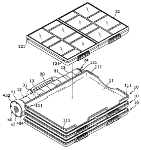
Referring to FIGS. 1, 2, and 6, a loose-leaf type storage
device is shown comprised of a pivot shaft 20, and a plurality of
flat rectangular storage cases 10. Each flat rectangular storage case
comprises a flat rectangular tray 11 and a flat rectangular case
10 12. The tray 11 and the case 12 are respectively molded from
plastics. The tray 11 is adapted to accommodate the case 12. The
case 12 defines a plurality of storage compartments respectively
covered with a respective transparent plastic iid. A positioning
structure is provided between the tray 11 and the case 12 so that the
case 12 can be positively held in position when put in the tray 11.
The tray 11 comprises a plurality of projecting strips 13I aligned at
one long side, and a plurality of barrels 13 respectively formed
integral with the projecting strips 131 and aligned in a line. The
projecting strips 131 of the trays 11 of the flat rectangular storage
cases 10 are so arranged that the barrels 13 of the trays 11 of the
flat rectangular storage cases 10 are aligned in a line for the
insertion of the pivot shaft 20. The pivot shaft 20 is inserted
through the barrels 13 of the trays 11 of the flat rectangular storage
4
CA 02444547 2003-10-10
cases 10, having a hollow head 21 disposed a~t one end, namely, the
first and stopped at one end of the aligned barrels 13 of the trays 11
of the flat rectangular storage cases 10 and the other end, namely,
the second end extended out of the other end of the aligned barrels
13 of the trays 11 of the flat rectangular storage cases 10 and
mounted with an end cap 24, which is stopped at the other end of
the aligned barrels 13 of the trays 11 of the flat rectangular storage
cases 10. After installation of the pivot shaft 20 in the aligned
barrels 13 of the trays 11 of the flat rectangular storage cases 10,
the trays 11 can be respectively turned about the pivot shaft 20.
There is a loose-leaf (tray) positioning structure provided
between the pivot shaft 20 and the trays 11 of the flat rectangular
storage cases 10. As illustrated in FIC S. 1 and 6, the loose-leaf
positioning structure comprises a plurality of spring leaves 22
1~ respectively formed integral with the pivot shaft 20 and
longitudinally aligned in a line, each spring leaf 22 having a raised
engagement portion 221 at the free end, and a plurality of locating
grooves 132 respectively formed inside flee barrels 13. When
turning one tray 11 about the pivot shaft 20 to a particular angle,
the locating grooves 132 of the barrels 13 of the tray 11 are forced
into engagement with the raised engagement portions 221 of the
corresponding spring leaves 22 at the pivot shaft 20, and therefore
the tray 11 is locked in position. ~y applying a biasing force to the
s
CA 02444547 2003-10-10
tray 11, the locating grooves 132 of the barrels 13 of the tray 11 are
disengaged from the raised engagement portions 221 of the
corresponding spring leaves 22 at the pivot shaft 20.
Referring to FIGS. 5A, SB, and SC, after loading of the
cases 12 in the trays 11, the storage cases 10 can be arranged in a
stack (see FIG. SA), or turned about the pivot shaft 20 relative to
one another to the desired angle (see FIGS. SB and SC).
There is also provided a positioning structure adapted to
lock the case 12 to the corresponding tray 11. The positioning
structure comprises a plurality of springy hooks 111 respectively
formed integral with the peripheral wall of the tray 11, and a
plurality of retaining grooves 121 respectively disposed at the
peripheral wall of the case 12 and adapted to receive the springy
hooks 111 at the tray 11.
Referring to FIGS. 1 and 6 again, a handle 30 is provided
having two barrels 31 extended from the two distal ends and
respectively coupled to the pivot shaft 20. Through the handle 30,
the user can conveniently carry the loose-Ieaf type storage device
by hand.
Referring to FIG. 6 again, the aforesaid end cap 24
comprises a semispherical head 241, a plug portion 242 insertable
into the second end (the end remote from the head 21) of the pivot
shaft 20, and an angled locating slot 253 formed in the plug portion
b
CA 02444547 2003-10-10
242. The pivot shaft 20 has a projecting block 25 disposed inside
the second end. During installation, the angled locating slot 253 is
aimed at the proj acting block 25, and then the plug portion 242 of
the end cap 24 is plugged into the second end of the pivot shaft 20,
and then the end cap 24 is rotated through an angle relative to the
pivot shaft 20, and thus the end cap 24 is locked to the pivot shaft
20 and prohibited from axial movement relative to the pivot shaft
20.
Referring to FICTS. 6~~, a rotary anchoring structure 40 is
IO provided comprising a plurality of female screws 221 respectively
axially disposed inside the hollow head 21 of the pivot shaft 20, a
cylindrical block 4I inserted into the hollow head 21, the
cylindrical block 41 having a peripheral stop flange 43 stopped
outside the hollow head 21 of the pivot shaft 20, a non-circular
plug hole, for example, crossed plug hole 42 axially disposed at the
center, and a springy pawl 44 projecting from the periphery outside
the hollow head 21 of the pivot shaft 20, a ratchet cap 45 capped on
the cylindrical block 41, the ratchet cap 45 comprises a ratchet 451
meshed with the springy pawl 44, an outward. peripheral flange 452
stopped outside the hollow head 21 of the pivot shaft 20, a plurality
of screw holes 453 disposed at the outward peripheral flange 451
and respectively connected to the female screws 221 inside the
hollow head 21 of the pivot shaft 20 by screws 454, and a center
7
CA 02444547 2003-10-10
through hole 455 axially disposed at the center and aimed at the
crossed plug hole 42. A crossed-shaft stand 46 is inserted through
the center through hole 455 and plugged into the crossed plug hole
42 to support the loose-leaf type storage device on a flat surface in
vertical. When installed, the storage cases 10 can be turned with
the pivot shaft 20 and the ratchet cap 45 relative to the cylindrical
block 41 and the crossed-shaft stand 46 in one direction through
3bo°.
Referring to FIG. 3, the trays II of the storage cases 10
each have a plurality of hang holes 14 for hanging on wall nails or
the like.
As indicated above, the loose-leaf type storage device can
be horizontally placed on a flat surface, or set in vertical and
supported on a stand by means of the rotary anchoring structure 40,
or hang on a wall by means of the hanging holes 14 at the trays 11.
When placed on a flat surface, set in vertical, or hung on a
wall, the storage cases 10 can be respectively turned about the
pivot shaft 10 relative to one another and then positioned in any of
a series of angles by means of the engagement between the raised
engagement portions 221 of the spring leaves 22 and the locating
grooves 132 of the barrels 13 for convenient arrangement of
storage items in the cases 12. ~'hrough the handle 30, the user can
conveniently carry the loose-leaf type storage device by hand.
s
CA 02444547 2003-10-10
A prototype of loose-leaf type storage device has been
constructed with the features of FIGS. I~8. The loose-leaf type
storage rack functions smoothly to provide all of the features
discussed earlier.
Although a particular embodiment of the invention has been
described in detail for purposes of illustration, various
modifications and enhancements may be made without departing
from the spirit and scope of the invention. Accordingly, the
invention is not to be limited except as by the appended claims.
9