Note: Descriptions are shown in the official language in which they were submitted.
CA 02444914 2003-10-24
WO 02/085219 PCT/US02/15245
1
1 FERMORAL NAIL INTRAMEDULLARY SYSTEM
2 FIELD OF THE INVENTION
3 The present invention generally relates to an intramedullary
4 system for coupling bone portions across a fracture
therebetween and, more specifically, to an intramedullary hip
6 pinning system for rigidly interconnecting a femoral head
7 portion to the remaining portion(s) of the femur and across a
8 fracture or fractures in the area of the femoral neck or the
9 shaft of the femur or combinations of such fractures.
11 BACKGROUND OF THE INVENTION
12 Bones are. the hard parts of the skeleton found in
13 vertebrates. In its most basic construct, bones are formed of
14 a relatively soft, spongy cancellous material surrounded by a
much harder cortex. The cancellous bone yields under relatively
16 low loading, while the much more dense cortical bone supports
17 much higher loading.
18 A hip joint is a heavily stressed, load-carrying bone
19 joint in the human body. It is essentially a ball and socket
joint formed by the top of the femur which rotates within a cup-
21 shaped acetabulum at the base of the pelvis. When a break or
22 fracture occurs adjacent to the top of the femur, the separated
23 portions of the femur must be held together while healing
24 occurs.
Historically, there have been a number of techniques used
26 for treatment of fractures of the proximal end of the femur.
27 In early parts of this century, patients were merely placed in
28 bed or in traction for prolonged periods, frequently resulting
29 in deformity or death.
In the 1930s, the Smith-Peterson nail was introduced.
31 This device was inserted into the intramedullary canal of the
32 femur resulting in immediate fixation of hip fractures, early
33 mobilization of the patient, and a lower morbidity and
CA 02444914 2003-10-24
WO 02/085219 PCT/US02/15245
2
1 mortality. A number of nails have been introduced for fracture
2 fixation of the femur in its proximal end, including the Jewett
3 Nail and Enders Nail.
4 Intramedullary nails have been inserted down the entire
length of the femoral canal to provide a basis for the fixation.
6 Threaded wires, standard bone screws or cannulated bone screws
7 were then inserted through or along side the proximal nail and
8 into the femoral head to provide fixation and rotational
9 stability. The conventional nails did not provide compression
of the proximal bone fragments against each other. Also, in
11 longer nails the distal tip of the nail tended to rotate out of
12 plane which forced the surgeon to locate the distal screw holes
13 using fluoroscopy by a method commonly known as "free-handing".
14 In the 1960s, the compression hip screw was introduced,
resulting in improved fixation of the proximal femur. A lag
16 screw assembly was inserted into the femoral head, a plate was
17 attached to the lateral femur, and a compression screw joined
18 the two. These implants provided a more rigid structure for the
19 patient and allowed the surgeon to compress the fractured
fragments against each other thereby decreasing the time to
21 mobility. A number of compression hip screws have been
22 introduced for fracture fixation about the proximal femur,
23 including the Dynamic Hip Screw.
24 During implantation these compression hip screws require
an incision at least equal to the length of the plate being used
26 which extends operative time and blood loss. The side plate
27 also creates a protuberance on the lateral side which provides
28 an annoyance to the patient. Compression hip screw systems also
29 fail to provide adequate compression in oseteogenic patients
because the lag screw assembly threads fail to obtain sufficient
31 purchase due to poor bone stock. Poor purchase is known to
32 contribute to nonunion, malunion and the lag screw assembly
33 eroding through the superior bone of the head of the femur in
CA 02444914 2003-10-24
WO 02/085219 PCT/US02/15245
3
1 a condition known as "cut out". Additionally, many patients are
2 dissatisfied with the results of compression hip screw surgery
3 because of the excessive sliding to a medial displacement and
4 shortening position which leads to a change in gait.
Newer devices and inventions include additions to the
6 nail and lag screw assembly to ease or eliminate the need to
7 locate the distal screw holes and improve the fixation. These
8 newer devices are commonly classified as "expanding devices" and
9 expand in size after placement to fill the intramedullary
cavity. Freedland, U.S. Patent No.s 4,632,101, 4,862,883 and
11 4,721,103, Chemello, U.S. Patent No. 6,077,264 and Davis, U.S.
12 Patent No. 5,057,103 describe a method of fixation which
13 provides points which contact the internal cortical wall. In
14 these patents a mechanism is actuated deploying arms or anchor
blades through the cancellous bone to contact the inner cortical
16 wall. These methods are complex and difficult to retract should
17 the nail or lag screw assembly require extraction. Further, the
18 screws do not deploy through the cortical bone.
19 Other expanding devices provide surface contact with the
internal cortical wall resulting in a wedge effect. Kurth, U.S.
21 Patent No. 4,590,930, Raftopoulos, U.S. Patent No. 4,453,539 and
22 Aginski, U.S. Patent No. 4,236,512, among others have described
23 mechanisms which deploy or expand with a molly bolt concept.
24 These methods are complex and difficult to retract should the
nail or lag screw assembly require extraction and, also, do not
26 deploy through the cortical bone.
27 Bolesky, U.S. Patent No. 4,275,717 was the first to
28 discuss engagement within the cortical wall. However, Bolesky's
29 invention does not address controlled penetration into the wall
and required permanent implantation of the actuation rod. In
31 addition, Bolesky does not address the fundamental problem of
32 the actuation rod's protrusion extramedullarly into the
33 surrounding musculature.
CA 02444914 2003-10-24
WO 02/085219 PCT/US02/15245
4
1 In U.S. Patent No.s 5,976,139 and 6,183,474B1, Bramlet et
2 al describe a surgical anchor which has deployable tangs. These
3 tangs are simple in design, internally positioned, yet easily
4 deployed into, and if desired through, the cortical bone
providing improved purchase for compression of a fracture,
6 especially in osteogenic bone. These tangs are just as easily
7 retracted should the device require explantation.
8 Approximately 10 years ago Howmedica (Rutherford, New
9 Jersey, United States) was the first to produce the "Gamma
Nail", named for its similarity in shape to the Greek letter,
11 and other designs soon followed. These devices combined
12 desirable aspects of both intramedullary nails and compression
13 hip screws. These intramedullary hip compression screws
14 required a few small incisions, allowed capture of the most
proximal fragments of the femur, rigid fixation of the most
16 proximal and distal fragments, and a sliding lag screw assembly
17 or anchor which fits within a barreled sleeve for allowing
18 improved compression of the fragments as the patient ambulates
19 and begins to bear weight on the fractured limb. The nails are
typically held in place on the distal end through interference
21 forces with the intramedullary canal and through the use of
22 locking screws.
23 The Gamma Nail's shape accommodates the relative shape of
24 the greater trochanter and femoral neck and head fragments, and
the shape of the hip is therefore preserved. Nonunions are less
26 frequent because bone-to-bone contact is maintained and the bulk
27 of an intramedullary hip screw blocks excessive sliding.
28 Intramedullary hip screws work best in reverse obliquity
29 fractures, a fracture, in which compression hip screws are least
effective.
31 Osteogenic bone still provides a poor medium for purchase
32 of the lag screw assembly of the Gamma Nail inhibiting adequate
33 compression and rotational stability. Longer nails continue to
CA 02444914 2003-10-24
WO 02/085219 PCT/US02/15245
1 see the distal tip of the nail rotating out of plane forcing the
2 surgeon to locate the distal screw holes by the free-hand
3 method. The free-handing technique leads to an increased
4 surgical time and exposes the surgeon and patient to increased
5 radiation dosages.
6 Clearly a need exists for a system which is superior to
7 the, " gold standard," of compression hip screws while
8 minimizing the surgical insult to the human body. Such a
9 system, as disclosed and claimed herein, includes a simple,
effective and controllable fixation device which allows greater
11 purchase of the lag screw assembly within the femoral head,
12 improved compression across the fracture line, provides a means
13 of rotational stability both in the femoral head and in the
14 femoral shaft, and minimizes the need for additional distal
incisions to locate and place locking screws. This system
16 allows the surgeon a choice of penetration distance within the
17 femoral head and femoral shaft fixation based upon the injuries
18 presented and the desired level of treatment. Finally, this
19 system allows explantation to occur as easily as implantation.
21 SUMMARY OF THE INVENTION
22 An intramedullary nail system is provided for coupling
23 bone portions on opposite sides of a fracture. The
24 intramedullary nail system according to the invention is
especially suitable for installation within the medullary canal
26 of a fractured long bone, such as found in an arm or leg. In
27 one embodiment of the present invention, the intramedullary nail
28 system includes an elongated rod with radial portals which allow
29 passage of locking screws or anchoring tangs and a lag screw
assembly. The rod has a distal end and a proximal end with
31 internal threads. A lag screw assembly having an externally
32 threaded portions. The radial portals in the distal end allow
33 passage of internally deployable and retractable anchoring
CA 02444914 2003-10-24
WO 02/085219 PCT/US02/15245
6
1 tangs or cortical screws. A radial portal in the proximal end
2 accommodates a sleeve which passes through the intramedullary
3 nail and through which the lag screw assembly passes freely
4 while preventing rotation of said lag screw assembly. A
compression screw engages the sleeve and cooperates with the
6 internal threads of the lag screw assembly trailing end
7 providing axial translation of the lag screw assembly within the
8 sleeve. The proximal end has an axial portal for an end cap
9 with external threads on the trailing end which engages the
internal threads of the intramedullary nail. The end cap has
11 a parabaloid leading end which engages the sleeve thereby
12 preventing translation and rotation of said sleeve.
13 When the intramedullary nail is placed into position the
14 anchoring tang assembly is actuated to deploy the tangs out from
their stowed position into the cortical bone. The tangs are
16 deployed to any desired position thereby achieving a desired
17 fixation based upon the quality of the bone.
18 In one embodiment, cortical screws may be placed to
19 secure the intramedullary nail with the surrounding cortical
bone. In another embodiment, the tang assembly is actuated and
21 the tangs are deployed to any desired position thereby achieving
22 the desired fixation based upon the quality of the bone.
23 The sleeve is coaxially inserted over the lag screw
24 assembly's trailing end and through the intramedullary nail.
An end cap is threaded into the intramedullary nail with it's
26 leading end contacting and frictionally holding the sleeve. By
27 providing interference against the sleeve, the sleeve is
28 prevented from altering its position either through translation
29 or rotation.
The compression screw passes through the sleeve and
31 engages the lag screw assembly. As the compression screw is
32 tightened the lag screw assembly and associated first bone
33 portion are pulled against the intramedullary nail and second
CA 02444914 2003-10-24
WO 02/085219 PCT/US02/15245
7
1 bone portion resulting in compressive forces being applied
2 across the fracture.
3 The intramedullary nail is preferably cannulated to allow
4 passage of one or more anchoring tang assemblies. These
anchoring tang assemblies are inserted from the proximal end
6 towards the distal end and the tangs deployed by means of an
7 actuator driver. An alternate embodiment describes a retracted
8 anchoring tang assembly which is permanently placed within the
9 distal end of the intramedullary nail and is deployed or
retracted by means of an actuator driver from the proximal end
11 of the intramedullary nail.
12 The lag screw assembly preferably contains a permanently
13 placed anchoring tang assembly stored in a retracted position
14 within the leading end. The tangs are deployed or retracted
from the trailing end of the lag screw assembly.
16 The anchoring tang assembly contains arcurate shaped tangs
17 that are permanently attached to the assembly's main body.
18 These tangs are initially formed into a prescribed position for
19 storage. As the assembly is actuated, and the tangs deploy, the
tangs are formed into their final shape through interaction with
21 the portal of either the intramedullary nail or the lag screw
22 assembly.
23 The compression screw preferably contains a patch of
24 ultra-high molecular weight poly-ethylene (UHMWPE) within the
threads. This provides constant positive engagement between the
26 compression screw external threads and the lag screw assembly
27 internal threads.
28 The end cap preferably contains a patch of ultra-high
29 molecular weight poly-ethylene (UHMWPE) within the threads.
This provides constant positive engagement between the end cap
31 external threads and the intramedullary nail internal threads.
32
CA 02444914 2003-10-24
WO 02/085219 PCT/US02/15245
8
1 In its final position the end cap exerts a force upon the sleeve
2 which inhibits the sleeve from sliding or rotating out of a
3 prescribed position.
4 Other objectives and advantages of this invention will
become apparent from the following description taken in
6 conjunction with the accompanying drawings wherein are set
7 forth, by way of illustration and example, certain embodiments
8 of this invention. The drawings constitute a part of this
9 specification and include exemplary embodiments of the present
invention and illustrate various objects and features thereof.
11
12 DESCRIPTION OF THE DRAWINGS
13 FIG. 1, is a longitudinal perspective view of the preferred
14 embodiment intramedullary system in an exploded state;
FIG. 2, is a view, partially in longitudinal cross section, of
16 the intramedullary system placed in the intramedullary canal of
17 a fractured bone using cortical screws as a method of fixation;
18 FIG. 3, is a view, partially in longitudinal cross section, of
19 the intramedullary system placed in the intramedullary canal of
a fractured bone using a tang assembly as a method of fixation;
21 FIG. 3A, is an enlarged, cross section view of the tang assembly
22 in FIG. 3;
23 FIG. 3B, shows the stowed tang assembly from FIG. 3A;
24 FIG. 3C shows the insertion/deployment/retraction instrument
of FIG. 3A;
26 FIG. 4A, is an enlarged, cross section view of the
27 intramedullary nail in FIG. 1;
28 FIG. 4B, is a side view of FIG. 4A;
29 FIG. 4C, is an end view of FIG. 4B;
FIG. 5, is an enlargement of the lag screw assembly in FIG. 1;
31 FIG. 6A, is an enlargement of the tang assembly in FIG. 3A;
32 FIG. 6B, is an enlargement of the stowed tang assembly from FIG.
33 3B;
CA 02444914 2010-05-14
9
FIG. 6C, is a top view of FIG. 6B;
FIG. 7A, is an enlargement of the sleeve in FIG. 1;
FIG. 7B, is a cross section view of FIG. 7A;
FIG. 7C, is an end view of FIG. 7A;
FIG. 8A, is an enlargement of the end cap in FIG. 1;
FIG. 8B, is a top view of FIG. 8A;
FIG. 9A, is an enlargement of the compression screw in FIG. 1;
FIG. 9B, is a top view of FIG. 9A.
DETAILED DESCRIPTION
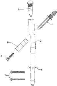
The individual components of the assembly, as illustrated in FIG. 1, are
constructed of implantable grade stainless steel alloys in the preferred
embodiment but
could also lbe constructed of implantable grade titanium alloys, as well.
Other materials
having the requisite properties, of strength and inertness, may be used. These
components consist of the lag screw assembly 1, the nail body 2, the tang
assembly 3,
the sleeve 4, the compression screw 5, and the end cap 6 and the optional
cortical
screws 7.
The lag screw assembly 1 is described in detail in U.S. Patent 6,183,474 Bi,
as
is compression screw 5, which disclosure may be referred to for further
details. The
external features of the lag screw assembly are indicated in FIG. 5. The
threads 8
engage the cancellous bone within the femoral head on the medial or proximal
side of
the fracture line; the tang 9 is also located on the medial or proximal side
of the
fracture line as shown in FIG. 3. However, the tangs 9 are fully retracted
into the body
of the lag screw and remains that way until the lag screw assembly is fully
positioned
within the femoral head. When the tangs 9 are deployed through opening 43 into
the
femoral head, the tangs 9 penetrate the cortical bone, greatly increasing
purchase (axial
fixation) and rotational stability of the lag screw assembly. The tangs 9 are
fully
CA 02444914 2003-10-24
WO 02/085219 PCT/US02/15245
1 reversible if removal of the lag screw is ever required. As
2 shown, the bone screw threads and the tangs are preferred,
3 however either one of the structures may be used, alone, to
4 attach the lag screw assembly to the bone. The shaft 10 is of
5 a "double D " cross section which interfaces with bore 27 (FIG.
6 7B)'and end configuration 31 (FIG. 7C) of the sleeve in such a
7 way as to allow axial translation or slide of the lag screw
8 while preventing rotation relative to the sleeve. This sliding
9 prevents penetration of the femoral head by the proximal end of
10 the lag screw as the fracture compresses from patient load
11 bearing.
12 The nail body (FIG. 4A,B, C) is designed for antegrade
13 insertion into the intramedullary canal of the femur. It is
14 anatomically shaped to the axis of the canal and has a medial
to lateral bend angle H. The proximal outside diameter W of the
16 body is greater than the distal outside diameter M due to
17 narrowing of the canal and to allow the lag screw clearance
18 radial bore 11 to be large enough to pass the threaded diameter
19 8 of the lag screw 1 and provide a sliding fit to the outside
diameter L of the sleeve 4. The axis of clearance bore 11 is
21 at an angle V with respect to the distal diametral axis. This
22 angle V is such as to allow proper positioning of lag screw 1
23 within the femoral head. Both the proximal axial bore 15 and
24 the distal axial bore 14 are of circular cross section. Distal
bore 14 is sized to permit a sliding fit with the tang body 20.
26 Four bores or tang portals 12 are located on a 90 degree radial
27 spacing penetrating from the distal outside diameter M into the
28 distal bore 14, on axes which form an angle J to the distal
29 outside diameter M. This angle J is critical to the proper
formation and exit of the tang 21. The clearance holes or bores
31 13 of FIG.4B pass through the distal outside surface and wall
32 into the distal bore 14 and continue on the same axis through
33 the opposite wall and outer diameter. The clearance holes 13 are
CA 02444914 2003-10-24
WO 02/085219 PCT/US02/15245
11
1 such as to allow passage of the threaded portion of the cortical
2 screw 7 (FIG.1) . A frusto-conical feature 18 (FIG.4A) provides
3 a transition between the circular bore 14 and the square bore
4 19. The square bore 19 serves three purposes: it provides
clearance through the distal end of the nail body 2 for passage
6 of a guide pin, used during fracture alignment and installation
7 of the of the nail body into the intramedullary canal, it
8 provides a sliding fit for the square forward protrusion 23
9 (FIG.6A) of tang assembly 3, and it acts as a "vent" hole for
any organic material within the bore 14 which is being pushed
11 ahead of the tang during tang installation. It must be noted
12 that the forward most clearance holes 13 also intersect the
13 frusto-conical featurel8 and will act as vents for organic
14 material during tang insertion after the square protrusion 23
has engaged and filled square bore 19. The internal threads 16
16 at the proximal end of the nail body 2 provide for instrument
17 interface, as do slots 17. The threads 16 are used for
18 attachment and the slots 17 for radial alignment. The internal
19 threads 16 also engage the external threads 34 (FIG.8A) of end
cap 6.
21 The tang assembly 3 has four equally sized and radially
22 spaced tangs 21 which are preformed to radius R. The radius R
23 (FIG.6B) on each tang 21 results in a dimension between the
24 trailing ends of opposing legs which is greater than the outside
diameter of tang body 20 and the bore diameter 14 of nail body
26 2. The tang body 20 is circular in cross section and sized for
27 a sliding fit within nail body borel4 with a leading edge
28 chamfer 22 which transitions into the leading protrusion 23
29 which has a square cross section and leading end taper 24. Tang
body 20 contains an internally threaded bore 25 which is the
31 instrument interface for the instrument used to insert and
32 deploy the tang. It must be noted that threaded bore 25 is not
33 needed for tang retraction. FIG. 6A illustrates the deployed
CA 02444914 2003-10-24
WO 02/085219 PCT/US02/15245
12
1 shape of tang assembly 3 which is the shape it assumes after the
2 tangs 21 have been forced through the tang exit portals 12 of
3 nail
4 body 2.
Insertion/deployment of the tang may occur after insertion
6 of the nail body into the intramedullary canal. For tang
7 assembly 3 insertion/deployment/retraction, the
8 insertion/deployment/retraction instrument 47 (FIG. 3C) is
9 employed. It has a shaft 44, one or more externally threaded
end (s) 45 and guide 46. Shaft 44 is preferably circular in
11 cross section with a diameter sized to allow reasonable
12 flexibility or bending about the longitudinal axis as it travels
13 through the nail body proximal bore 15 and distal bore 14 in
14 order to follow the centerlines of both bores 14 and 15. The
guide 46 provides a sliding fit in bore 14 and interacts with
16 bore 14 in such a way as to center the shaft 44 within bore 14.
17 Guide 46 also stabilizes shaft 44 in bore 14 to prevent shaft
18 44 from buckling under axial compressive load encounted during
19 tang assembly retraction. The insertion/deployment instrument
is threaded into tang-threaded bore 25. The tang is now
21 inserted through nail body bore 15 and into nail body bore 14.
22 Since the distance between opposing tang legs 21 is greater than
23 the bore diameter 14 due to radius R, the interference with bore
24 14 forces the legs 21 inward in an elastic manner and insertion
continues. As the tang assembly travels down bore 14, any
26 organic material which has accumulated in bore 14 is pushed
27 ahead and forced out through square bore 19 of nail body 2 and
28 through clearance holes 13. Further insertion causes the tang
29 assembly 3 leading square taper 24 to contact the square bore
19 of the nail body 2. Since both cross sections are square,
31 no engagement will occur until they are radially aligned which
32 may or may not occur without some slight rotation of the tang
33 assembly 3 using the insertion/ deployment instrument. After
CA 02444914 2003-10-24
WO 02/085219 PCT/US02/15245
13
1 alignment occurs and by virtue of this alignment, the tang
2 leading protrusion 23 will slide freely in square bore'19 and
3 the tangs 21 and the nail body 2 tang portals 12 will now be
4 aligned. The tang 3 continues past tang exit holes 12 and is
fully inserted when the tang body leading edge chamfer 22 makes
6 contact with the nail body frustro-conical feature 18 at point
7 C of FIG. 3B. In this position, the tang leading protrusion 23
8 protrudes through the end of nail body 2 to point A and the
9 trailing end of the tangs 21 are just past tang portals 12. The
tangs are now in position to be deployed. To deploy the tangs,
11 an axial force is exerted by the insertion/deployment/retraction
12 instrument 47 in the opposite direction as for insertion. This
13 causes the tang assembly 3 to translate back up bore 14 and the
14 sharp ends of tangs 21 to encounter tang portals 12. Since the
tangs 21 were elastically compressed inward by bore 14 they will
16 now spring outward forcing the sharp end of tang legs 21 into
17 tang exit holes 12. Further translation of the tang assembly
18 3 forces the tang legs through the tang exit holes 12. Due to
19 the diameter and angle of the tang portals 12, the tangs 21 are
formed in such a manner as to emerge almost perpendicular to the
21 femoral cortex. Continued translation of the tang assembly3
22 causes the tangs 21 to penetrate the femoral cortex. During
23 this time, tang leading'square protrusion 23 is still engaged
24 by the nail body square bore 19 thus preventing rotation of tang
assembly 3 in bore 14 during deployment and preventing unwanted
26 twisting of the tangs 21. The tang assembly 3 can be deployed.
27 fully or partially and is self locking in any position due to
28 the almost perpendicular entry angle into the cortex. After
29 deployment, the insertion /deployment /retraction instrument is
unthreaded from tang threaded bore 25 and removed. The nail
31 body 2 is now fixed axially and rotationally in the
32 intramedullary canal. FIG.3A shows the tang assembly 3 in the
33 fully deployed position having translated a distance from point
CA 02444914 2003-10-24
WO 02/085219 PCT/US02/15245
14
1 A in FIG. 3B to point B of FIG. 3A. The tangs 21 are fully
2 retractable. They are retracted by applying a force on the tang
3 assembly 3 with the insertion/deployment/retraction instrument
4 42 in the opposite direction as deployment (opposite of arrow
direction in FIG. 3A) until the tang assembly 3 comes to rest
6 at points C and A in FIG. 3B.
7 Distal fixation of the nail body 2 can be accomplished
8 without use of tang assembly 3. This is accomplished by using
9 the cortical screws 7 (FIG.1 and FIG. 2). The cortical screws
7 are placed through the lateral femoral cortex and through
11 clearance holes 13 in the nail body 2, then through the medial
12 femoral cortex as shown in FIG. 2. The cortical screws are not
13 used in conjunction with distal tang fixation and cannot be
14 passed through clearance holes 13 if there is a tang assembly
3 inserted into nail body 2.
16 Sleeve 4 is utilized to secure lag screw assembly 1 into
17 clearance bore 11 after implantation of the lag assembly 1-and
18 nail body 2 in the femur. The outside diameter L (FIG.7B) is
19 sized for a sliding fit in bore 11. The sleeve 4 has a circular
bore 27 and a small length (D) of "double D" bore 31 at the
21 leading end. The leading bore also contains a countersink 30.
22 Between the leading and trailing ends is a tapered cross section
23 29. The trailing outside diameter has a diamond knurl 26 and
24 the circular bore 27 contains a countersink 28 at the trailing
end. After the lag screw 1 is in position its trailing end
26 protrudes partially or fully through nail body 2 bore 11. The
27 leading end of sleeve 4 containing bore 31 is inserted into bore
28 11 and the bore 31 aligned with the similarly shaped lag screw
29 shaft 10. The sleeve 4 is inserted further into bore 11 thus
mating, with the aid of countersink 30, the sleeve 4 and lag
31 screw shaft 10. The sleeve 4 is placed within bore 11 such that
32 the leading end of taper 29 or shoulder F in FIG. 7A is located
33 properly with respect to bore 15 of nail body 2 ( FIG. 2 and 3).
CA 02444914 2003-10-24
WO 02/085219 PCT/US02/15245
1 The end cap 6 is inserted into the proximal end of nail body 2
2 until external threads 34 (FIG.BA) contact the internal threads
3 16 of nail body 2. The end cap 6 is then rotated clockwise by
4 means of hexagonal recess 32 to engage the threads. End cap 6
5 contains a patch of ultra high molecular weight polyethylene 35
6 which acts as a thread locking element to help prevent unwanted
7 loosening of end cap 6. As the end cap advances its leading end
8 spherical radius 37 contacts sleeve taper 29 forcing sleeve 4
9 against the opposite side of bore 11 indicated P (FIG. 4C). At
10 this time the taper 29 is in contact with one end of bore 11 and
11 the knurl surface 26 is in contact with the opposite end of bore
12 11, indicated S in FIG. 4C. The taper 29 interaction with end
13 cap spherical radius 37 prevents any translation of sleeve 4 in
14 bore 11 in the direction of the lag screw and interaction of the
15 end cap spherical radius 37'with the sleeve taper shoulder F
16 prevents translation of the sleeve in the opposite direction.
17 Interaction of knurled surface 26 of sleeve 4 and bore 11 in
18 conjunction with interaction of end cap spherical radius 37 and
19 sleeve 4 taper 29 prevents rotation of sleeve 4 in bore 11.
Sleeve 4 is now fixed in translation and rotation. Therefore,
21 lag screw 1 is now fixed in rotation but free in axial
22 translation.
23 With the lag screw 1 fixed to one side of the fracture and
24 the nail body 2 and sleeve 4 affixed to the other, the
compression screw 5 can be utilized to draw the two assemblies
26 together and compress the fracture. The externally threaded end
27 40 of the compression screw 5 is inserted through the trailing
28 end of sleeve 4 and mated with the internal threads 48 in the
29 trailing end of lag screw 1. Advancing the screw utilizing
drive recess 42 the threads engage. An ultra high molecular
31 weight polyethylene patch 39 in the compression screw thread 40
32 provides thread locking. As the threads further engage,
33 compression screw chamfer 38 contacts sleeve 4 countersink 28
CA 02444914 2003-10-24
WO 02/085219 PCT/US02/15245
16
1 causing lag screw 1 to be drawn towards nail body 2 as the
2 compression screw 6 is further rotated thus compressing the
3 fracture.
4 It is to be understood that while we have illustrated and
described certain forms of the invention, it is not to be
6 limited to the specific forms or arrangement of parts herein
7 described and shown. It will be apparent to those skilled in
8 the art that various changes may be made without departing from
9 the scope of the invention and the invention is not to be
considered limited to what is shown in the drawings and
11 described in the specification.
12