Note: Descriptions are shown in the official language in which they were submitted.
CA 02445032 2003-10-09
120754
A SYSTEM AND METHOD FOR MONITORING
THE CONDITION OF A HEAT EXCHANGE UNIT
Background of the Invention
The present invention relates generally to systems and methods for the
condition-
based monitoring of machines. More specifically, the present invention
pertains to
monitoring the condition of heat exchange units.
In conducting a condition-based maintenance (CBM) program for machines, or
components of machines, analysts using physical evaluation and a knowledge
base,
can make a decision on the relative health of various components of the
machine, or
the machine itself. Typically, sensors are mounted at various locations on a
machine
to detect at least one, or more, physical phenomenon that is produced by the
operation
of the machine. The detection and analysis of the phenomena is ideally
performed in-
situ in order to provide a real-time analysis of the condition of the machine
or
component of the machine.
For example, vibrations emanating from the operation of a bearing assembly are
detected using an accelerometer placed in proximity to the bearing. The
vibrations of
the bearing assembly produce a vibrational energy that is measurable in
amplitude and
frequency. Data obtained during the operation of the bearing assembly is
compared to
data stored within a database that usually includes a plurality of parameters
relative to
the operation of the bearing assembly. The parameter limit data is obtained
from an
analysis of the bearing assembly. An analyst assesses the condition of the
bearing
assembly by comparing the operational data of the bearing assembly to the
stored
parameter data.
Other physical phenomena such as sound or temperature may also be detected and
analyzed for condition based monitoring of a machine. For example, the
temperature
and flow rate of fluid media in a heat exchanger may be analyzed for
determining the
1
CA 02445032 2003-10-09
120754
health of the heat exchange unit. A heat exchanger performance monitor is
disclosed
in U.S. Patent No. 4,766,553 (hereinafter referred to as the "'S53 Patent").
The
system of the '553 Patent discloses the use of temperature transmitters
mounted to an
evaporator or condenser, which are electronically linked to software
programmed to
input temperature readings into equations for analysis of the performance of
the heat
exchanger.
At least with respect to mobile assets, such as locomotives, automated CBM has
not
been utilized for assessing the health of a heat-exchange unit. The monitoring
of a
heat exchange unit typically includes a subjective analysis of the temperature
output
of the exchange unit, which may lead to inconsistent results from analyzer to
analyzer. In the operation of similar machine assets, such as in the operation
of a fleet
of mobile assets subject to a condition based monitoring system, the
generation of
parameter threshold requirements for individual heat exchange units may not be
practical. In addition, condition-based monitoring of stationary heat exchange
units
does not factor changing ambient environmental conditions into the analysis of
the
health of a unit
With respect to locomotives, non-contact infrared temperature sensors have
been used
to take temperature readings of components of a locomotive. Specifically,
infrared
sensors have been mounted subjacent a railroad track at locomotive service
stations.
When the locomotive is stopped for servicing at a station, the infrared
sensors are
activated and detect the temperature of bearing assemblies of the locomotive
wheel
casings. However, such sensors may not be practically installed for operation
with
internal components of some machines. Indeed, some internal operating
components
cannot be practically analyzed using conventional stationary contact or non-
contact
sensors.
BRIEF SUMMARY OF THE INVENTION
Accordingly, a system and method are described herein for the monitoring the
condition of a heat exchange unit having a first fluid and a second fluid
passing
through the heat exchange unit. The second fluid is a coolant for lowering an
elevated
temperature of the first fluid by heat exchange.
2
CA 02445032 2003-10-09
120754
The system comprises at least one sensor for taking temperature readings
representative of temperatures of the first fluid and/or the second fluid. The
temperature readings may include at least two temperatures associated with
either the
first fluid or at least two temperatures associated with the second fluid. In
an
exemplary embodiment, the sensor is a portable non-contact infrared sensor,
which is
hand-held by a technician for taking the temperature readings. The sensor is
held in
spaced relation to a plurality of discrete points along the surface of the
heat exchange
unit to take the temperature readings.
The system is also equipped with a processor, in communication with the
sensor, in
which data representative of the temperature readings is entered. A database,
in
communication with the processor, comprises data that is representative of at
least
one predetermined condemning limit associated with a measure effectiveness of
the
heat exchange unit. The condemning limit data associated with the
effectiveness of
the heat exchange unit is obtained from an analysis of a population of like
heat
exchange units. Particularly in the operation and maintenance of a fleet of
mobile
assets, component parts such as the heat exchange unit are purchased from the
same
manufacturer. The units are manufactured from the same materials and
specification,
so data gathered from the population of units is analyzed to identify
parameter limits.
The processor is programmed to calculate a measure effectiveness of the heat
exchange unit by comparing the data representative of the temperature
readings. In
addition, the processor compares the measure of effectiveness of the heat
exchanger
to the predetermined condemning limit, stored in the database, and associated
with
the effectiveness of the heat exchange unit for the population of like units.
The
processor then generates a signal indicative of the condition of the heat
exchange unit.
In operation, the sensor is positioned proximal to the heat exchange unit to
take
temperature readings of the first fluid or second fluid. In a preferred method
of
operation, the surface temperatures comprise an inlet surface temperature for
the first
fluid entering the unit and an outlet surface temperature for the first fluid
exiting the
unit. In addition, an outlet surface temperature for the second fluid exiting
the heat
exchange unit is taken. The limits associated with the effectiveness of the
heat
3
CA 02445032 2003-10-09
120754
exchange unit and the processor generate a signal that is indicative of a
condition of
the heat exchange unit.
In addition to the above-described condemning limit related to the
effectiveness of a
heat exchange unit, the database may also contain data representative of one
or more
operating parameters of the heat exchange unit and/or the vehicle in the case
of
analyzing mobile assets. In such an embodiment, the database may contain at
least
one measure of effectiveness obtained from analyzing the like population; and
the
measure of effectiveness is associated with one or more operating parameters
of the
heat exchange unit, including, but not limited to ambient temperature,
geographic
location of a mobile asset, and elevation/altitude of the mobile asset,
humidity,
barometric pressure, and the time period within a calendar year. An additional
sensor
may be used to detect a level of at least one of the operating parameters of
the heat
exchange unit. In operation, the system detects the operating parameters of
the heat
exchange unit, and identifies the corresponding predetermined condemning limit
associated with the operating parameter. The measure of effectiveness is then
compared to the predetermined condemning limit to determine a condition of the
heat
exchange unit.
The system and method of the present invention is particularly advantageous
because
a technician having minimum skill level or training can operate the invention.
The
present invention also provides immediate feedback relative to the condition
of the
heat exchange unit. The processor is programmed to automatically calculate the
measure of effectiveness. A technician simply takes the temperature readings
necessary for the calculation and enters the readings into the processor along
with the
other operating parameter concerning, for example, ambient conditions and/or
predetermined time periods associated with the operation of the heat exchange
unit.
The processor performs an algorithmic function and generates the signal
concerning
the condition of the heat exchange unit.
BRIEF DESCRIPTION OF THE DRAWINGS
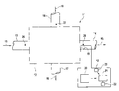
FIG. 1 is a schematic of a heat exchange unit incorporating the present system
for
monitoring the condition of a heat exchange unit.
4
CA 02445032 2003-10-09
120754
FIG. 2 is a flow chart describing the method for monitoring the condition of
the heat
exchange unit.
FIG. 3 is graph plotting the percent effectiveness parameter limits with
respect to
predetermined time periods of a calendar year.
FIG. 4 is an algorithm that may be used in the system and method for
monitoring the
condition of the heat exchange unit.
DETAILED DESCRIPTION OF THE INVENTION
The present invention for a system and method for monitoring a condition of a
heat
exchange unit preferably utilizes non-intrusive, non-contact temperature
sensors to
take at least one surface temperature reading of the heat exchange unit to
determine
the health of the heat exchange unit.
The present invention in some instances may be described in the context of the
environment of the operation of an internal combustion engine for motor
vehicles.
Such heat exchange units may be commonly referred to as "intercoolers;"
however,
the present invention is not limited to an intercooler, but may be used with
any heat
exchange unit such as condensers, evaporators, boilers, air coolers or pre-
coolers, or
other devices having heat transfer surfaces. However, the present invention
may also
utilize contact sensors mounted in proximity to the unit or probe the fluid to
take a
direct temperature reading of the first fluid and/or second fluid.
With respect to FIG. 1, a schematic illustrates the system 10 in conjunction
with a
heat exchange unit 11. The heat exchange unit 11 generally includes a heat or
energy
exchange chamber 12, through which a first fluid 15 and second fluid 18 flow.
The
first fluid 15 enters the chamber 12 at an elevated temperature as a result of
the
operation of a machine. For example, with respect to a turbo-charged internal
combustion engine, air discharged from the turbo charger is heated and must be
cooled prior to recirculation to the turbo charger. Water maintained within
the engine
cooler system is directed through the chamber 12 , via conduits to cool the
discharged
am.
S
CA 02445032 2003-10-09
120754
The first fluid 15 enters the chamber 12 via first inlet tube 13, and is
discharged from
the chamber 12 via the first outlet tube 14. A second fluid 18, or coolant,
enters the
chamber 12 via a second inlet tube 16, and exits the chamber 12 via the outlet
tube 17.
The second fluid 18 enters the chamber having a temperature lower than the
elevated
temperature of the first fluid 15. As the first fluid 15 and second fluid 18
pass through
the chamber 12, heat exchange occurs between the first fluid 15 and second
fluid 18,
whereby the first fluid is cooled to an acceptable operating temperature. The
heat
exchange between the two fluids takes place without physical contact between
the
fluids. Typically, the first fluid 15 and/or second fluid 16 pass through a
series of
conduits or manifold systems within the chamber 12 to facilitate the heat
exchange
between the two fluids.
The system shown in FIG. 1 includes at least one sensor 20 for taking a
plurality of
temperature readings of the exterior surface of the heat exchange unit 12, and
a
processor 21 for analyzing the temperature readings to determine the condition
or
health of the heat exchange unit 11. In an exemplary embodiment, the sensor 20
is a
hand-held portable infrared non-contact thermometer. One may maneuver such
sensors to different positions with respect to the heat exchange unit 11 in
order to take
a sufficient number of temperature readings to analyze the health of the heat
exchange
unit 11. Infrared guns or infrared thermography cameras are available from a
variety
of manufacturers or distributors including Raytek Inc., Image Systems, Inc.,
Grainger
Inc. or Flir Systems, Inc.
The system 11 may also be equipped with one or more additional sensors or
monitors
23, as shown in FIG.l, to detect operating parameters that may influence the
operation
of the heat exchange unit 11, which will be described in more detail below.
The type
of sensor 23 used will depend on the specific operating parameter to be
detected. For
example, a thermometer may be used for detecting an ambient temperature, or a
GPS
(global positioning satellite) unit may be used for determining a geographic
location
of the heat exchange unit.
The system 10 may also include at least one contact sensor 19 mounted in one
of
tubes 13, 15, 16 and 17 to take a direct temperature reading of the first
fluid 15 and
6
CA 02445032 2003-10-09
120754
second fluid 16. Such sensors 19 are known to those skilled in the art of
conditioned
based monitoring systems. The sensor 19 is preferably linked to a data access
area for
downloading temperature readings from the sensor 19. The temperature reading
of
the sensor 19 is entered into the processor as described below.
The sensor 20 is positioned relative to a plurality of predetermined discrete
points
along the exterior surface of the unit 11. With respect to the above-described
non-
contact infrared sensors, the sensor 20 is positioned in spaced relation to
the discrete
points. An analysis of like heat exchange units should empirically determine
the areas
on the unit from which the temperature readings are taken. In operation, the
sensor 20
is used to take temperature readings representative of the temperatures of the
first
fluid 15 and/or the second fluid 18 at the points from which the temperature
readings
are taken. The temperature readings are transmitted to the processor 21, which
is
capable of calculating a computation that is representative of the
effectiveness of the
heat exchange unit 11. The computation is expressed as a percentage of the
effectiveness of the unit 11 on a scale of 0% to 100%.
The temperature readings may be manually entered into the processor, or the
sensors
20 may be directly linked to the processor to automate the transmission and
entry of
the temperature readings. The processor 21 is programmed with an arithmetic
equation to calculate a measure of effectiveness of the heat exchange unit 11
using the
temperature readings of the exterior surface of the heat exchange unit 11. At
least two
temperatures associated with the first fluid 15 and/or two temperatures
associated
with the second fluid 18 are compared to one another to calculate the measure
of
effectiveness. In an exemplary embodiment, at least one temperature
representative
of the first fluid and at least one temperature reading representative of the
temperature
of the second fluid (or coolant) is taken for analysis. For example, a
temperature (also
referred to as an inlet temperature, or Tl) representative of the first fluid
entering the
chamber 12 is taken; a temperature (also referred to as an outlet temperature
or T2);
and, a temperature associated with the second fluid entering the chamber 12
(also
referred to as T3).
7
120754
CA 02445032 2003-10-09
As mentioned above, the temperature readings, T1, T2 and T3, are measurements
of
the surface temperature of the heat exchange unit 11 taken at predetermined
discrete
points. An adjustment factor may be incorporated in the algorithm in order to
accurately reflect the temperature readings of the first fluid 1 S and second
fluid 18,
and/or the calculation of the effectiveness of the heat exchange unit 11. A
sample
algorithm for calculating the effectiveness computation of the heat exchange
unit 11
may be characterized as a ratio of the change in the inlet temperature (T 1)
of the first
fluid 15 and the outlet temperature (T 2) of the first fluid, to the
difference in the
between inlet temperature (T 2) of the first fluid and the inlet temperature
(T3) of the
second fluid. An equation representing the algorithm is listed below:
(Tl-T2)A +B
(Tl-T3)
where T 1 is the inlet temperature of the first fluid;
T 2 is the outlet temperature of the first fluid;
T 3 is the inlet temperature of the second fluid; and,
A and B are the adjustment factors.
The adjustment factors A and B may include predetermined numeric constants
that
may be calculated using regression analysis of the temperature readings, T 1,
T 2 and
T 3. The adjustment factors may be empirically calculated by comparing
temperature
readings taken from more precise contact sensors that directly measure the
temperature of the fluids, and the temperature readings of the exterior
surface of the
heat exchange unit 11. The adjustment factors are preferably determined from a
population of like, or similar, heat exchange units.
A database 22, in communication with the processor 21, contains at least one
limit
associated with the measure of effectiveness of the heat exchange unit 11. The
limit
may also be referred to as a condemning limit, in the sense that if the
measure of
effectiveness exceeds the condemning limit, a signal is generated that
indicates a
8
CA 02445032 2003-10-09
120754
health of the unit. The predetermined limit data relative to measure of
effectiveness
of the heat exchange unit 11 is obtained from an analysis of a selected
population of
like heat exchange units.
A method for the present invention is depicted in the flow charts in FIG. 2.
With
respect to Steps 31 and 32, the sensor 20 is positioned relative to a
plurality of
discrete points on the surface of the heat exchange unit 11. For example, with
reference to FIG. 1, temperature readings may be taken at points 26 and 27,
along the
exterior surface of inlet tubes 13 and 16, respectively. A temperature reading
may be
taken at point 28 along the surface of the outlet tube 14. Similarly, contact
or probe
sensors may be positioned at the points 26, 27 and 28, to directly read the
temperature
of the fluids 1 S and 18.
In Step 33, the temperature readings are then transmitted and/or entered into
the
processor 21, where the temperature readings are used to calculate the measure
of
effectiveness of the exchange unit 11. The measure of effectiveness of the
exchange
unit 11 is calculated as a percentage, from 0% to 100%, of the operating
efficiency of
the heat exchange unit 11. In an intermediate Step 36, or as a step combined
with the
calculation of effectiveness measurement, the temperature readings are
adjusted using
the adjustment factors (A and B referred to above) to reflect a temperature of
the first
fluid 15 and second fluid 18 at points 26, 27 and 28.
In Step 34, the measure of effectiveness, calculated in Step 33, is compared
to the
limits maintained in the database 22 in communication with the processor 21.
The
condemning limits are associated with the effectiveness of the heat exchange
units
and are obtained from an empirical analysis of a population of like heat
exchange
units. The limits may include at least one minimum condemning limit above
which
the heat exchange unit 11 effectively operates, and/or below which the heat
exchange
unit 11 requires maintenance, or at least an inspection.
With respect to Step 35, the processor generates a signal indicative of the
condition of
the heat exchange unit. For example, if the measure of effectiveness falls
below the
condemning limit, the processor may generate a warning signal that the heat
exchange
unit requires maintenance. The signal may take the form of a pass/fail
response that
9
CA 02445032 2003-10-09
120754
leads to an inspection of the unit. In addition, the processor 21 and database
22 may
maintain and generate multiple signals corresponding to different measures of
effectiveness. For example, a percent effectiveness of 70% may generate a
signal that
requires inspection of the unit 11, while a percent effectiveness computation
of 60%
may generate a signal of impending failure of the unit 11, which must be
replaced.
The database 22 may also include operating parameters associated with the
operation
of the heat exchange unit 11. For example, the operating parameters may
include
ambient environmental conditions that may influence the operation of the heat
exchange unit 11, such as ambient temperature, and geographic location of the
unit
11. In addition, the operating parameters may include predetermined time
periods
within a calendar year associated with the operation of the heat exchange unit
11 and
the ambient environmental conditions.
These operating parameters may be especially useful for units 11 operating on
mobile
assets, such as locomotives that travel over extended time periods and
distances and
are subject to changing ambient environmental conditions. These ambient
conditions
directly affect the effectiveness of the heat exchange unit. The heat exchange
unit 11
may operate less efficiently under elevated temperatures, which typically
occur in the
spring and summer months of April through August. That is to say, the heat
exchange
unit 11 must operate more efficiently during these warmer months in order to
perform
the same level of work at a less efficient level in cooler months.
Accordingly, the
condemning limits for the measure of effectiveness for the months of April
through
August will be higher than the limits corresponding to the remaining months of
the
year. In addition, the geographic location, including the elevation of the
unit 11 may
also be considered, so the database 22 is able to assess that a heat exchange
unit
operating during the month of May at 75° should operate at or above an
efficiency
level of 76%.
By way of example, condemning limits corresponding to the effectiveness of the
heat
exchange unit 11 have been plotted on the graph shown in FIG. 3, with respect
to
operating parameters associated with the operation of the heat exchange unit
11. The
percent effectiveness is plotted along the "y" or vertical axis, and the
calendar months
CA 02445032 2003-10-09
120754
are plotted along the horizontal, or "x" axis. The graph includes a condemning
limit
A, B, and C for each of three different time periods of the year. The limit A
for the
months of February through March is 76%, the limit for the months of April
through
August is 81%, and the limit for the months of September through January is
73.5%
During the winter and spring months of January through April, the temperatures
of the
condemning limits may be relaxed and the heat exchange unit 11 may be
permitted to
operate less efficiently without maintenance. If the percent effectiveness
drops below
73.5% during the months, the processor 21 should generate a signal indicating
that
action is required. Similarly, the condemning limits A and B for the
respective time
periods serve as a minimum percent effectiveness above which the heat exchange
unit
must operate during the respective calendar time periods. In addition, the
condemning
limit C may serve as a minimum condemning limit. If the percent effectiveness
falls
below C (73.5%) at any time of the year, the processor should signal that
action is
necessary. The condemning limit A (81%) may similarly serve as a maximum
limit,
so that a measure of effectiveness equal to or greater than A, regardless of
the time of
year, will always result in a passing signal.
To the extent that the detected level of the operating parameter may not equal
to or
fall within given ranges of the operating parameter data, the processor may be
programmed to adjust or normalize the measure of effectiveness relative to the
difference in operating parameters. Similarly, the predetermined condemning
limit
may also be adjusted to account for a difference in the detected level of the
operation
parameters and the associated operating parameter data.
With respect to FIG. 4, the processor may be programmed to follow the below-
described algorithm incorporating steps for considering at least one operating
parameter. After the measure of effectiveness computation, X, is calculated in
step
41, it is compared to the maximum condemning limit, Y, and the minimum
condemning limit, Z. If the measure of effectiveness X exceeds the maximum
limit
Y, then no action is required and a corresponding signal is generated, as
shown in
steps 43 and 45. Similarly, in steps 42 and 46, if the measure of
effectiveness X is
11
120754
CA 02445032 2003-10-09
equal to or less than the minimum-condemning limit Z, then a signal
corresponding to
the necessary action required is generated.
If the measure of effectiveness X does not exceed the maximum X or minimum Y
parameter limits, then step 44 is initiated to identify the time period of
operation
within the calendar year to the corresponding condemning limit 1, 2 or 3. A
time
period operating parameter is used by way of example. The foregoing
description
could also be described using such operating parameters as ambient temperature
and
geographic location of the heat exchange unit 11.
As shown in steps 47 through 55, depending on the time of year, the measure of
effectiveness X will be compared to condemning limits l, 2 or 3. If the
measure
effectiveness X is equal to or exceeds the respective condemning limits l, 2
or 3
correspond to a predetermined time period, no action will be required. On the
other
hand, if the effectiveness computation X is equal to or less than the
respective
predetermined condemning limits l, 2 or 3, a signal indicative of the
necessary action
is generated.
In addition to the foregoing algorithmic functions with respect to time
periods and
corresponding condemning limits, the above-identified operating parameters
relative
to the ambient environment may be incorporated into analysis of the
computation of
the measure of effectiveness. For example, the ambient temperature may be
identified
with each respective time period of the calendar year. A predetermined
temperature,
or range of temperatures, may correspond to at least one condemning limit.
Accordingly, within a single predetermined time period, the database 22 may
maintain a plurality of condemning limits, wherein each condemning limit
corresponds to a predetermined temperature or temperature range.
Alternatively, the
processor and database 22 may be programmed to operate as a function of
predetermined temperatures and corresponding condemning limits, without
reference
to the previously described time periods. Similarly, the algorithmic functions
may
also factor the geographic location of the unit 11, so that the condemning
limit for the
measure of effectiveness may be associated with the combination of location of
the
unit at a predetermined time period and operating at an ambient temperature.
As one
12
120754
CA 02445032 2003-10-09
skilled in the art will appreciate, any combination of the operating
parameters may be
used to analyze the measure of effectiveness and assess the condition of the
heat
exchange unit 11.
While the invention has been described in what is presently considered to be a
preferred embodiment, many variations and modifications will become apparent
to
those skilled in the art. Accordingly, it is intended that the invention not
be limited to
the specific illustrative embodiment, but be interpreted within the full
spirit and scope
of the appended claims.
13