Note: Descriptions are shown in the official language in which they were submitted.
CA 02445307 2003-10-22
WO 02/088671 PCT/SE02/00827
A SEPARATION UNIT, A METHOD FOR SEPARATION, AND A DEVICE FOR
MOUNTING A SEPARATION UNIT IN A SEPARATION APPARATUS
TECHNICAL FIELD
The present invention relates to a modular separation system where a
separation unit is
separate from a mounting device that accommodates the separation unit in a
separation
apparatus. The separation unit is used in fluid-fluid extraction of an analyte
from a sample
fluid into a receiving fluid. The mounting device is an integral and permanent
part of a
separation apparatus and carries the necessary fluid fittings. The invention
also relates to
a separation system comprising the separation unit insertable into and
removable from a
mounting device. The invention also relates to a method for fluid-fluid
extraction of an
analyte from a sample fluid into a receiving fluid in a separation apparatus
according to
the invention.
BACKGROUND OF THE INVENTION
Separation (extraction) units according to the prior art, e.g. as described in
the reference
Jonsson, J.A. et al: "Automated system for the trace analysis of organic
compounds with
supported liquid membranes for sample enrichment", Journal of Chromatography
A, 665
(1994), pages 259-268, comprises two solid blocks usually made of polymeric
materials
which are identical in the way they are machined, i.e. they contain machined
holes for
fluid connectors, drilled holes from the end of these holes to the fluid
cavity which is
machined in the centre of each block. One block also contains pre-drilled
holes into which
screws will fit and the other block contains means to receive the screws,
essentially pre-
machined female connections in the block itself or as steel inserts. A polymer
sheet, often
referred to as the membrane, is clamped between the blocks and the screws are
tightened. The described extraction system is after this ready for use.
However, a system
assembled in this manner will need to be re-used because it involves so much
manual
work for exchanging the clamped polymer. A further disadvantage with these
systems is
that they are susceptible to carry-over problems associated with re-use.
Another
disadvantage is that the production of the systems is likely not to be able to
deliver the
best reproducibility as the blocks need to be machined and, furthermore, the
operation is
expensive. Since the assembly of the system is manual there is a risk that the
pressure
might not be uniform across the cavities and that the pressure will not be
consistent from
time-to-time when the system has been disassembled and reassembled again.
Furthermore, the production does not guarantee that the blocks exhibit a good
match
CA 02445307 2003-10-22
WO 02/088671 PCT/SE02/00827
2
when mounted and not tilted in relation to one another. Thus, if they are
tilted the
accessible membrane will differ and the extraction efficiency will decrease.
DESCRIPTION OF THE INVENTION
An object of the present invention is to provide a modular system with a
separate
separation unit and a mounting device that accommodates the separation unit in
a
separation system. A further object of the invention is to provide a mounting
device, which
is an integral and permanent part of a separation apparatus and carries the
necessary
fluid fittings. Another object of the invention is to provide a separation
system which
comprises a mounting device with a separation unit insertable therein and
removable
therefrom. It is a further object of the invention to provide a separation
system which
allows for automation of fluid-fluid extraction and which, furthermore, allows
for connection
to any final analysis device, e.g. a chromatograph, a spectroscopic device, a
flow injection
system etc. It is a still further object of the invention to provide a
separation apparatus,
which may be directly coupled to an analysis apparatus, e.g. a chromatograph,
a
spectroscopic device, a flow injection system etc. It is a still further
object of the invention
to provide a separation unit, which is easy and cheap to manufacture. If is a
further object
of the invention to provide a separation unit, which can be easily fitted into
a larger
mounting device for positioning the separation unit in a separation apparatus.
Further, it is
an object of the invention to provide such a mounting device for positioning
the separation
unit. It is also an object of the invention to provide a method for fluid-
fluid extraction which
reduces the amount of sample fluid and/or receiving fluid required, and which
allows for
the direct connection of the device to any final analysis device, e.g. a
chromatograph. It is
a further object of the invention to provide a separation unit, a method for
fluid-fluid
extraction and a device for mounting the separation unit in a separation
apparatus which
is less labour-extensive, i.e. in which the number of steps to be carried out
by an operator
before and during extraction and in the test procedure are reduced.
A further object is to provide a separation apparatus comprising a separation
unit, a
mounting device in which a separation unit is insertable into and removable
from.
A further object is to provide a separation apparatus comprising means for
exchanging
separation units.
CA 02445307 2003-10-22
WO 02/088671 PCT/SE02/00827
3
Another object according to the invention is to provide a modular system with
a separation
unit with multiple cavities. A further object is to provide a separation
apparatus comprising
means for moving the multiple cavity separation unit andlor rotating it.
The modular system according to the present invention with a separation unit
inserted into
the permanent mounting device gives the following advantages:
- No disassembly of the separation unit
- A one-time assembly of fittings to the mounting device
- Possible single-use of the fluid cavities, eliminates carry-over problems in
these
parts, and improves analytical precision .
- No operator handling of the separation medium reduces risk for contamination
and
reduces time consumption
- The pressurisation of the separation unit will be uniform from unit-to-unit
- Full automation possible, even when the cavities of the separation unit are
used
only once.
The process for producing the separation unit offers among the following
advantages:
- High unit-to-unit precision in dimensions
- Low manufacturing prize
According to a first aspect, the present invention relates to a separation
unit as defined in
claim 1.
The separation unit may contain a separation medium, which can be of any
nature, such
as chromatographic materials and/or a membrane, preferably a membrane. The
separation medium is arranged so that one or more analytes in the sample fluid
can pass
from the sample fluid via the separation medium to the receiving fluid. The
sample fluid
and the receiving fluid respectively can contact the separation medium
simultaneously or
sequentially.
When the present description mentions that the sample fluid cavity is
connected to the
receiving fluid cavity and the separation medium is a membrane support adapted
or
arranged so as to partly separate the sample fluid cavity from the receiving
fluid cavity, it
is meant that the sample fluid cavity, the receiving fluid cavity and the
membrane support
are arranged in relation to each other in a way that allows one or more
analytes in the
CA 02445307 2003-10-22
WO 02/088671 PCT/SE02/00827
4
sample fluid to pass from the sample fluid through the membrane support to the
receiving
fluid.
Where in the present context the expression "an analyte" is used, this should
be
understood as meaning "one or more species of analytes". Usually, a plurality
of analytes
is to be extracted in the separation unit according to the present invention.
The term "membrane support" should be understood as any material, including
synthetic
and organic materials, which is capable of at least partly separating two
immiscible or
partly miscible fluids or of facilitating the contact between two miscible
fluids. The
membrane support preferably has pores or perforations, which are adapted to
accommodate a fluid. Thus, in case of a hydrophilic membrane support, an
aqueous fluid
may be accommodated in the pores or perforations, and in case of a hydrophobic
membrane support, an organic fluid may be accommodated in the pores or
perforations.
The membrane support having ifs pores or perforations filled or partly filled
with a fluid
constitutes a membrane. In the present context, a "membrane" should be
understood as
any device or assembly capable of at least partly separating two immiscible or
partly
miscible fluids while allowing certain molecules to pass through the membrane
from one
fluid to another.
Alternatively, the membrane support may comprise a non-porous material, such
as a non-
porous polymeric material, such as silicon rubber. In the case of the membrane
support
comprising or being constituted by a non-porous material, the membrane support
may
constitute the membrane. If the non-porous material separates an aqueous fluid
from an
organic fluid, the non-porous material is normally wetted by the organic
fluid, in which
case the wetted non-porous material constitutes the membrane. If the non-
porous
material separates two aqueous fluids, the non-porous material is normally not
wetted by
fluid, in which case the non-porous material itself constitutes the membrane.
In the present context, the term "fluid-fluid extraction" should be
interpreted broadly, as
comprising any type of extraction between two fluids, such as liquids, or any
kind of
molecular diffusion between fluids, such as dialysis. According to the present
definition,
fluid-fluid extraction also comprises MMLLE (Microporous Membrane Liquid-
Liquid
Extraction). In the MMLLE technique as it has been demonstrated with gas
chromatography, an organic liquid is continuously moving during the extraction
step.
CA 02445307 2003-10-22
WO 02/088671 PCT/SE02/00827
MMLLE normally involves two valves of the kind normally used for liquid
chromatography
and an intermediate transfer of an extract, e.g. organic receiving fluid
containing analytes,
to a loop, thereby causing a more dispersed (diluted) sample. The transfer of
the extract
in this technique is normally performed by a gas pressure being exerted by the
support
5 gas flow in the gas chromatograph.
The sample fluid cavity preferably defines a volume of at most 50 ~,I, such as
at most 40
~,I, such as at most 20 p,1, such as most 10 ~,I, such as at most 5 ~.I, such
as at most 2 ~,I,
such as at most 1 ~,I, such as most 0.5 ~.I. The sample fluid cavity may be of
substantially
the same size as the receiving fluid cavity. The volume of the receiving fluid
cavity is at
most 50 w1, such as at most 40 p,1, such as at most 20 ~I, such as at most 10
~,I, such as at
most 5 g,1, such as at most 2 p.1, such as at most 1 ~,I, such as most 0.5
~,I.
Due to the small volumes of receiving fluid and sample fluid, which may be
accommodated in the separation unit, hazardous effects to an operating person
and to the
environment are reduced. Moreover, due to the small volumes, the separation
unit
enables extraction from low volumes of sample, yet preserving possibilities of
high volume
ratios between sample and receiving fluid, important to e.g. liquid-liquid
extraction. It
further enables direct connection between extraction and an analysis
apparatus, such as
a chromatograph. Further, the separation unit according to the invention
necessitates only
very few steps to be carried out by an operator, whereby automation of the
extraction
procedure and possibly of the subsequent analysis procedure is facilitated.
While the volume of the sample fluid cavity suitably is less than 50 w1, the
amount of
sample fluid used for extraction is usually higher, as, during extraction, a
flow of sample
fluid is preferably continuously led through the sample fluid cavity. Thus,
the amount of
sample fluid flowing through the separation unit may preferably be between 0.3
and 5 ml.
The receiving fluid may be stagnant, i.e. not flowing, during extraction, in
which case the
volume of receiving fluid used for extraction is approximately equal to the
volume of the
receiving fluid cavity.
The sample fluid may be an aqueous liquid or an organic liquid or a gas.
Examples of
aqueous liquids are any physiological liquid, e.g. chosen from the group
consisting of
whole blood, urine, sweat, plasma, serum, nasal secrete, cerebrospinal fluid
and other
CA 02445307 2003-10-22
WO 02/088671 PCT/SE02/00827
6
liquids from living organisms. It can also be a non-physiological liquid, e.g.
a liquid chosen
from the group consisting of river water, sea water, lake water, effluent
water, influent
water, drinking water, ground water or a fine dispersion of solid matter in
aqueous
solution, e.g. soil samples, food samples, plant samples, tissue samples or
aqueous
samples of dissolved airborne compounds, or liquid foodstuff e.g. juice, milk,
wine and
coffee. The sample volume is small and is between about 20 p1, more often 100
~,I, and
about 20 ml, preferably between 0.3 and 5 ml. Volumes outside the above-
defined range
may also be applicable, however in rare cases.
The analytes of interest in the sample are preferably compatible with the
final analysis
equipment and may for example be chosen from any group of volatile or semi-
volatile or
non-volatile organic or inorganic or organometallic compounds.
The receiving fluid may be a hydrophobic liquid, such as an organic liquid, or
an aqueous
liquid or a gas. The receiving fluid is preferably chromatography compatible
and may for
example be a hydrophobic organic liquid or a hydrophilic liquid, such as a
buffer. Thus, all
analytes in the liquid samples, which are soluble in both types of liquids,
can be analysed
by using the separation system according to the present invention,
particularly small
molecules (<1 kDa) which are or which can be uncharged. The receiving fluid
can also be
D
a gas.
The membrane support may be hydrophobic or hydrophilic, normally hydrophobic.
Ex-
amples of membrane supports are polytetrafluoroethylene (PTFE),
polyvinylidenedi-
fluoride (PVDF), polypropylene (PP), polyethylene (PE), polystyrene (PS),
polysulfone,
cellulose, polyethersulfone (PES) and silicone rubber. The membrane support
may be
provided with a stabilizing backing. The sample fluid containing the analytes
is separated
from the receiving fluid by the membrane support, serving as a phase
separator, thereby
facilitating the interaction, i.e. the analyte transfer, between the two
fluids in question
(interfacial support).
Additionally, the separation unit of the invention may be used in dialysis,
wherein
molecules diffuse from a first aqueous solution, e.g. blood or urine, through
a hydrophilic
or hydrophobic membrane, normally a hydrophilic membrane, to a second aqueous
solution.
CA 02445307 2003-10-22
WO 02/088671 PCT/SE02/00827
7
A suitable membrane support for many applications is a Celgard° 2400 or
2500, which is
a polypropylene polymer with elongated pores manufactured by Ceianese/Hoechst.
The
membrane support is usually provided in the form of strips or sheets, which
are cut into an
appropriate form prior or subsequent to assembling of the separation unit. The
receiving
fluid, preferably a hydrophobic liquid, fills the pores of the polymer as well
as the receiving
fluid cavity. Alternatively, the sample fluid fills the pores. In yet
alternative embodiments,
the pores may be filled with a hydrophobic fluid separating two aqueous
fluids, or the
pores may be fitted with an aqueous liquid separating two hydrophobic fluids.
The
receiving fluid or the sample fluid in the pores constitutes the membrane.
Membrane
support material made of PTFE are also suitable, e.g. Fluoropore FG from
Millipore and
TE 35 from Schleicher & Schuell.
The following membrane supports are, among others, applicable to the
separation unit
according to the invention:
Flat sheets, Hydrophobic:
Accurel~ PP, polypropylene, Akzo Nobel
Ceigard~ 2400, polypropylene, Celanese Corporation
Celgard~ 2500, polypropylene, Celanese Corporation
TE 35, PTFE with polyester backing, Schleicher & Schuell, Germany
Fluoropore FGLP, PTFE with polyethene backing, Millipore Corporation, USA
Fluoropore FHUP, PTFE, Millipore Corporation
Durapore GVHP, PVDF, Millipore Corporation
SM11807, PTFE, Sartorius, Germany
Spectrapor, PTFE with polypropylene backing, Spectrum Medical, USA
Flat sheets, Hydrophilic:
Micro PES, sulfonated polyethersulfone, Akzo Nobel
Polyamid PA 6, polyamid
Any other porous hydrophobic or hydrophilic, porous polymer or any micro-
porous metallic
film may be applied.
CA 02445307 2003-10-22
WO 02/088671 PCT/SE02/00827
8
The porosity of the membrane support may vary between 0 and 90%, preferably
between
40 and 85%. The average pore size is 0-10 ~.m, preferably about 0.01-0.5 ~,m.
The
thickness of the membrane support may vary between 10 and 500 pm, preferably
between 10 and 200 pm.
In operation, the sample, preferably an aqueous liquid passes the membrane.
Hydrophobic, uncharged molecules then distribute between the sample and the
membrane, most often with a much higher affinity for the membrane. The
analytes diffuse
into the receiving fluid in the receiving fluid cavity. The receiving fluid is
preferably kept
stagnant during extraction. Hence, extraction over time will lead to an
increase in analyte
concentration in the receiving fluid compared to the original sample.
The body portion comprises a first and a second wall member and means for
fixing the
wall members in relation to each other. The wall members are preferably made
from a
plastic material, such as a polypropylene. The wall members may be coated in
case the
separation unit is to be used with an aggressive solvent. Thus, they may for
example be
chromium, gold or platinum plated or they may be coated with a fluorinated
polymer such
as PTFE. The two wall members may be assembled by fitting of complementary
parts
provided on the two wall members, such as projections and fitting holes or
bores.
The body portion is flattened and defines an upper and a lower surface and at
least one
rim or edge portion. (n this case, the ratio between a maximal height of the
rim or edge
portion and a maximal diagonal dimension of the upper and lower surface is at
most 1 to
4, such as at most 1 to 5, 1 to 6, 1 to 8, 1 to 10, 1 to 12, 1 to 15, 1 to 18,
1 to 20, 1 to 25, 1
to 40, 1 to 60, or 1 to 80.
Grooves or cut-outs may be provided in one or both of the wall members so as
to provide
the sample fluid and/or the receiving fluid cavities. Thus, the sample fluid
cavity may be
limited by a groove or cut-out formed in the first wall member and, when a
membrane is
used as a separation medium, a first surface of the membrane support.
Likewise, the
receiving fluid cavity may be limited by a groove or cut-out formed in the
second wall
member and, when a membrane is used as a separation medium, a second surface
of the
membrane support.
CA 02445307 2003-10-22
WO 02/088671 PCT/SE02/00827
9
In a preferred embodiment of the separation unit, the first and second wall
members are
identical which facilitates mass production of the separation unit.
Preferably, each wall
member is provided with holes and bores arranged with a distance to a number
of
projections, which preferably epuals the number of bores or holes. Thus, the
projections
of one wall member will fit into the bores or holes of the other wall member
when pressing
the two members against one another. The first and the second wall members may
further
comprise means for indicating a correct mutual position of the wall members in
relation to
each other. Such indications may, e.g., comprise an optical indication such as
notch in the
wall material or a coloured dot. Alternatively, a protrusion may be provided
on one of the
surfaces of one of the wall members, whereby the protrusion prevents wrong
assembling
of the two wall members.
As discussed below in connection with the device for mounting the separation
unit in an
analyte separating apparatus, the notch for indicating a correct mutual
positioning of the
two wall members may also be used for fixing the separation unit in relation
to the device.
Preferably, the membrane support comprises a sheet or strip, which is arranged
between
the first and the second wall member.
The separation unit may be a disposable separation unit for one-time use only,
or it may
be re-used several times.
The separation unit can be moulded by e.g. injection moulding which makes it
possible to
produce identical first and second wall members. Moulding the two parts of the
separation
unit in the same mould assures high part-to-part precision in cavity geometry
and
dimension as well as perfect matching of opposing cavities (cf. Figure 2c).
One or more of the sample fluid inlets or outlets may comprise a pipe in the
body portion,
see for example Figure 14. All inlets and outlets may comprise a pipe. The
inlets or outlets
may extend at a substantially right angle or at an acute angle to one of the
upper and
lower surfaces of the body portion. Alternatively, at least one of the inlets
and outlets may
extend substantially parallel to one of the upper and lower surfaces of the
body portion.
When the inlets or outlets extend at a right or at an acute angle to one of
the upper and
lower surfaces, turbulence may be generated in the respective cavities.
Turbulence may
also be generated when the inlet and/or outlets, in particular the sample
fluid inlet, is bent
CA 02445307 2003-10-22
WO 02/088671 PCT/SE02/00827
so that the sample fluid takes a sharp turn before entering the sample fluid
cavity. A
turbulent flow may be desirable in the sample fluid cavity in order to
increase diffusion of
analytes from the sample fluid to the receiving fluid. The pipe or pipes are
preferably
integral with the body portion of the separation unit.
5
Preferably, the inner diameter of the inlets and outlets are substantially
equal to a
diameter or a maximal width of the grooves or cut-outs. However, the inlets
and outlets
may also have an inner diameter which is smaller or larger than a diameter or
maximal
width of the grooves or cut-outs, which might increase mass transfer within
the sample
10 fluid or decrease dispersion of receiving fluid.
In order to increase vortex generation and turbulence in the sample fluid
cavity, at least
the sample fluid cavity may comprise means, such as spoilers, for obstructing
the flow of
sample fluid through the cavity.
The grooves or cut-outs forming the receiving fluid and sample fluid cavities
preferably
extend longitudinally in the wall members. The inlets and outlets are
preferably arranged
at opposing ends of the two grooves.
In order to hold the membrane support in a fixed position between the two wall
members,
a surface of at least one of the wall members may have a projecting portion.
In that case
the grooves or cut-outs are preferably formed in the projecting portion. The
grooves or
cut-outs may be formed in the projection portion solely, or they may also
extend into the
material of the wall member material. The projection is preferably made from
the same
material as the wall members. It may be made from a flexible material in order
to facilitate
assembling of the two wall members.
In certain embodiments of the separation unit, the two wall members may be
releasably
secured in relation to each other solely by means of friction between portions
of the
respective wall members which facilitates assembly and disassembly of the
separation
unit so as to thereby facilitate mounting or exchange of the membrane support.
In further independent aspects, the invention further relates to the use of
the separation
unit for molecular diffusion, such as in dialysis, and to the use of the
separation unit for
molecular extraction.
CA 02445307 2003-10-22
WO 02/088671 PCT/SE02/00827
11
- In a second aspect, the present invention relates to a method for fluid-
fluid extraction
of an analyte from a sample fluid into a receiving fluid in a separation unit
as defined
in claim 13.
Due to the small volumes of receiving fluid in the receiving fluid cavity, the
receiving fluid
may be led directly from the receiving fluid outlet to an analysing apparatus,
such as a
chromatograph. Thus the distance between the receiving fluid outlet and the
analysing
apparatus may be minimised whereby undesirable dispersion is minimised.
By allowing the separation unit to be discarded and replaced with a new
separation unit,
frees an operator of the separation unit from disassembling the unit,
replacing the
membrane support and assembling the unit again. Further, the separation unit
may be
delivered to the user or operator in a ready-to-use form, whereby the user
only needs to
unpack the unit and mount it in an appropriate set-up.
It should be understood that any feature and functionality described above in
connection
with the first aspect of the invention may also be incorporated in or be
applicable to the
method of the second aspect of the invention and vice versa.
In a third aspect the present invention relates to a device for mounting a
separation unit in
a separation apparatus as defined in any of claims 8-10.
Preferably, means are provided for pressing against two sides of the
separation unit, so
as to closely seal the separation medium and the cavities of the separation
unit. Thus, the
mounting device may have an upper and a lower part between which parts the
separation
unit may be placed, the two parts being movable towards each other so as to
create a
pressure on the separation unit. Both the upper and lower part may be movable,
or
alternatively only one of them may be movable. The upper and lower parts may
comprise
injectors and extractors for receiving fluid and sample fluid, whereby one
single relative
movement between the upper and lower part of the device not only confers an
appropriate
pressure on the separation unit but also properly connects injectors and
extractors to the
inlets and outlets of the separation unit.
CA 02445307 2003-10-22
WO 02/088671 PCT/SE02/00827
12
The device may comprise or be operatively connected to a control system for
controlling
positioning of at least the receiving fluid extractor in relation to the
receiving fluid outlet
and/or of the sample fluid injector in relation to the sample fluid inlet. The
control system
may further be adapted to control positioning of the receiving fluid injector
in relation to the
receiving fluid inlet and/or of the sample fluid extractor in relation to the
sample fluid
outlet.
In a further aspect the invention relates to a separation system as defined in
claim 11.
In a further additional aspect the invention relates to a separation apparatus
as defined in
claim 12.
The separation unit is either automatically replaceable (utilising a cassette
or equivalent
means for replacing the used unit with a new unit) or in case many cavities
are present in
the separation unit the used cavities are automatically replaced by new
cavities, see for
example Figures 2a and 2b.
The separation system according to the invention works in the following manner
The mounting device opens up
- The new separation unit is introduced automatically or new cavities in the
separation unit are automatically put into position
- The mounting device closes - rendering the system ready for operation.
When the separation unit utilises a membrane as a separation medium, the
receiving fluid
cavity is provided with the receiving fluid volume desired, whereby the
receiving fluid
extractor will be filled with the receiving fluid. During the sample flow
through the
separation unit, analytes of interest partition between the sample and the
membrane,
diffuse into the receiving fluid cavity and are accumulated therein. When the
flow of
sample fluid through the separation unit has been stopped, i.e. when the
extraction
operation is over, i.e. after 1-120 min, more often after 5-60min, mostly
after 10-30 min,
the receiving fluid containing the analytes is displaced via a fluid delivery
system into the
analysis apparatus by introducing additional receiving fluid into the
receiving fluid cavity.
When the analytes in the receiving fluid cavity and the receiving fluid
extractor have been
displaced, the separation unit and the receiving fluid extractor contain pure
receiving fluid,
CA 02445307 2003-10-22
WO 02/088671 PCT/SE02/00827
13
i.e. they have been regenerated and are ready for a new sample flow.
Optionally, an
intermediate washing step is included.
Alternatively, when the separation unit utilises e.g. chromatographic material
as a
separation medium the sample fluid and the receiving fluid might be introduced
sequentially. The separation medium can in these cases be confined in the
sample fluid
cavity or in the receiving fluid cavity or in both cavities.
The whole analysis operation or parts thereof including the steps of feeding
the separation
unit with receiving fluid and sample, the sample flow interruption, the
regeneration of the
stagnant phase with fresh receiving fluid, the separation, the detection and
the data
accumulation can be performed automatically, e.g. controlled by a computer
system.
The total analysis time is 5-120 min, mostly 10-40 min.
BRIEF DESCRIPTION OF THE DRAWINGS
Fig. 1 a) illustrates a device for mounting a separation unit according to the
invention in a
separation apparatus,
Fig. 1 b) is a front view of the device of Fig. 1 a),
Fig. 1 c) is a side view of the device of Figs. 1 a) and 1 b),
Fig. 2a) illustrates a separation system wherein A is the mounting device, B
are holes) to
access the cavities of the separation unit, C is the separation unit and D is
connecting
tube,
Fig. 2b) illustrates an example of a separation unit containing multiple
cavities.
Fig. 2c) illustrates an example of a cross-section of the two wall members of
the body
portion wherein F is the first wall member and G the second wall member,
Fig. 3 is an exploded view illustration of a third embodiment of a separation
unit according
to the invention,
CA 02445307 2003-10-22
WO 02/088671 PCT/SE02/00827
14
Fig. 4 is an illustration of the separation unit of Fig. 3 when assembled,
Fig. 5 illustrates a wall member of the separation unit of Figs. 3 and 4,
Fig. 6 is a bottom view of the wall member Fig. 5,
Fig. 7 is a cross-sectional illustration along line A-A of Fig. 6,
Fig. 8 is a cross-sectional illustration along line B-B of Fig. 6,
Fig. 9 is an illustration of detail C of Fig. 8,
Fig. 10 is an illustration of detail F of Fig. 8,
Fig. 11 is an illustration of a wall member for a fourth embodiment of the
separation unit
according to the invention,
Fig. 12 is a side view of the wall member of Fig. 11,
Fig. 13 is a bottom view of the wall member of Figs. 11 and 12,
Fig. 14 is a cross-sectional view along line A-A of Fig. 13,
Fig. 15 illustrates a detail of a separation unit according to the invention
mounted in a
mounting device according to the invention,
DETAILED DESCRIPTION OF THE DRAWINGS
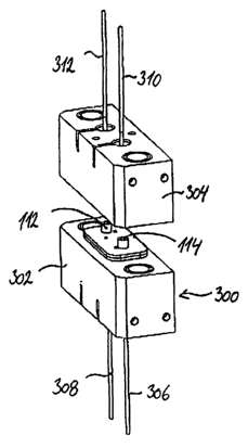
Figs. 1 a), 1 b) and 1 c) illustrate a device 300 for mounting a separation
unit 100 in a
separation apparatus. The device comprises a lower part 302 through which
receiving
fluid is led to and from the separation unit via a receiving fluid injector
306 and a receiving
fluid extractor 308, and an upper part 304 through which sample fluid is led
to and from
the separation unit via a sample fluid injector 310 and a sample fluid
extractor 312. The
receiving fluid extractor 308 may be directly connected to an analysis device.
CA 02445307 2003-10-22
WO 02/088671 PCT/SE02/00827
In Figs. 1 a), 1 b) and 1 c) the separation unit 100 is inserted into the
device 300 in a way
that prevents wrong positioning of the separation unit in relation to the
device. After
insertion of the separation unit 100, the lower part 302 of the device and the
upper part
304 are clamped together, thus creating a pressure that seals the grooves of
the
5 separation unit against the membrane support. Either one of the upper and
lower parts
302 and 304 may be movable, or they may both be movable. They can be manually
moved by mechanical means, which may be electrically, pneumatically or
hydraulically
supported.
10 The separation unit can be inserted from the long end (Fig. 1 b) or from
the short end (Fig.
1 c).
There may be provided an indication, such as a light diode, that is lit when
the separation
unit is correctly positioned, thus either triggering the upper and lower parts
302 and 304 to
15 clamp the separation unit or telling the operator that he or she may close
the device.
Fig. 2a) illustrates a separation system according to the invention wherein
the separation
unit has a circular shape with multiple.cavities.
Fig. 2b) illustrates the inside of the separation unit, which is used in the
separation system
in Fig. 2a),
Fig. 2c) illustrates a cross-sectional view of the body portion with the two
wall members of
a separation unit provided with guiding protrusions for accurate positioning
of the two
parts.
Fig. 3 is an exploded view illustration of a separation unit 100. The unit
comprises two
identical wall members 102, each of which has an upper surface 104 and a lower
surFace
106. The two wall members 102 and means for fixing the wall members in
relation to each
other together define a body portion of the separation unit. On each wall
member, a
groove 108 is provided in a protrusion 110. The groove 108 of one of the wall
members
constitutes a sample fluid cavity, whereas the groove 108 of the other one of
the wall
members constitutes a receiving fluid cavity. Inlets 112 and outlets 114 are
provided in
one of the wall members for inlet and outlet of sample fluid, whereas
identical inlets and
outlets are provided in the other one of the wall members for receiving fluid
inlet and
CA 02445307 2003-10-22
WO 02/088671 PCT/SE02/00827
16
receiving fluid outlet. A membrane support 116 is provided between the two
wall
members. Projections 118 are provided on each one of the wall members. The
projections
118 fit into corresponding holes 120, which are further, provided in each one
of the wall
members. Notches 121 are provided in each one of the wall members so as to
indicate to
the person assembling the wall members that they are positioned correctly in
relation to
each other when he or she assembles the separation unit. Fig. 4 illustrates
the assembled
separation unit having an upper and a lower surface 122 and an edge porfiion
124.
Figs. 5-10 illustrate a wall member 102 of the separation unit of Figs. 3 and
4. In Fig. 7,
which is a cross-sectional illustration along line A-A in Fig. 6, the inlet
112 and outlet 114
are funnel-shaped so as to be complementary with a conical end of a conical
end portion
of an injector and extractor for sample fluid and receiving fluid,
respectively. Fig. 8 is a
cross-sectional illustration along line B-B of Fig. 6. As illustrated in the
detail of Fig. 9, the
groove 108 has a triangular shape. Any other geometry of the groove is
possible such as
rectangular, rounded, etc.
Figs. 11-14 illustrate a wall member 202 for a second embodiment of the
separation unit
according to the invention. The wall member comprises a groove 208
constituting a cavity
for either the sample fluid or the receiving fluid. The groove is provided in
a protrusion
210. The cross-sectional view of Fig. 14 illustrates that an inlet 212 and an
outlet 214 are
arranged at acute angles to an upper surFace 204 of the wall member. The inlet
and outlet
are partly funnel-shaped. Projections 218 and holes 220 are provided for
fitting two
identical wall parts together, so as to form a separation unit, wherein the
inlets and outlets
for sample fluid and receiving fluid are arranged at an acute angle to the
upper and lower
surface of the separation unit.
Fig. 15 illustrates a detail of a separation unit 100 according to the
invention mounted in
the device of Figs. 15-17, more particularly the fitting of the receiving
fluid extractor 308
into the receiving fluid outlet of the separation unit. The receiving fluid
extractor 308
comprises a tube 314 provided with an opening 316 in a wall of the tube, the
opening 316
being aligned with the groove 108 of the separation unit. In the tube 314, a
piston 318 is
provided which is moveable in an upward and a downward direction as indicated
by arrow
319. The piston comprises a plunger 320. When analytes are diffusing into the
receiving
fluid in the groove 108, the piston 318 is either in a position in which the
plunger 320 is
above the opening 316 or in a position in which the plunger 320 blocks the
opening 316.
CA 02445307 2003-10-22
WO 02/088671 PCT/SE02/00827
17
When diffusion of analytes has completed, the receiving fluid 109 is
dislocated from the
groove 108, through opening 316, into the tube 314. The plunger 320 is
thereafter moved
downwards, pressing receiving fluid into e.g. a chromatograph, as indicated by
arrows
322. Before a fresh amount of receiving fluid is led into the groove 108, the
plunger 320
may be moved back to its initial position in which it blocks the opening 316
in the tube
wall. Moving receiving fluid in the groove 108 will now regenerate new
receiving fluid in
the membrane support. Thereafter the plunger is moved to a position above the
opening
316, and the groove 108 is filled with receiving fluid. The plunger 320 may
also be moved
to a position above the opening 316 prior to leading receiving fluid into the
groove 108 in
order to regenerate the membrane support. The piston and the plunger may be
spring
biased towards the position in which the plunger block the opening in the tube
wall. The
piston and the plunger may also be movable by means of e.g. hydraulic,
electric or
pneumatic driving means.
Preferably, the tube 314 is formed as a tube made from stainless steel with
the opening
316 being formed as a bore or drilled hole. Preferably, the plunger 320 is
moved so fast
when displacing receiving fluid into an analysis apparatus that a so-called
split-splitless
injector on a gas chromatograph may be used optimally. The tube 314 may have a
conical
outer shape, which facilitates insertion of the tube into the receiving fluid
outlet of the
separation unit.
The other injectors and extractors of the device of Figs. 1 a), 1 b) and 1 c)
may be designed
in a similar way.