Note: Descriptions are shown in the official language in which they were submitted.
CA 02445317 2003-10-24
WO 02/087670 PCT/GB02/01955
1
Improvements relating to Syringe Holders
This invention relates to syringe holders.
The syringe to be used with these holders will be of
the usual form, with a cylindrical capsule containing the
dose, which is captive by a plunger whose rod extends clear
of the rear end of the capsule. That rear end has a
radially projecting flange, usually annular with two flats,
20 while a needle projects axially from the reduced forward
end. A protective cap is generally provided to shield the
needle before use. Such a syringe will be referred~to as
of the kind described.
Such syringes can be used by themselves, but they are
small and "fiddly", and control is not easy. Also the
exposed needle is dangerous and after use it is important
to make it safe. Replacing the cap is not an answer, since
it can easily be removed again.
Therefore devices have been developed to contain the
syringe and to make it easier to use and to render it safe
after use. Some of these are quite complex, with trigger
release of a spring firing mechanism, and automatic spring
retraction to bring the needle back into a housing. But
they are not disposable items, .or at least they are rather
expensive to throw away after a single use, and they need
to be carefully unloaded of their syringes.
CA 02445317 2003-10-24
WO 02/087670 PCT/GB02/01955
2
The aim of this invention is to provide a basic
throwaway holder, which is easy to load with a syringe,
which makes the syringe secure when loaded, and which
preferably also offers a simple and reliable way of
irreversibly shrouding the needle after use.
According to the present invention there is provided a
syringe holder comprising a barrel with an open rear end to
receive a syringe of the kind described, said rear end
having means engageable behind the flange at the rear end
of the capsule once the syringe reaches its fully housed
position, thereby to hold the capsule within the barrel,
characterised in that the rear end of the barrel has a
socket to receive and locate said flange and a gate that
hinges in a radial plane from a non-obstructing position
clear of the socket to an obstructing position preventing
escape of the capsule flange from the socket but not
impeding operation of the plunger, the gate being captive
in said obstructing position.
The gate may be'~integrally moulded with the barrel and
connect thereto by a thin web which acts as its hinge.
Preferably, the gate hinges through a slot to intrude
into the socket, snap fastening therein as it reaches said
obstructing position.
CA 02445317 2003-10-24
WO 02/087670 PCT/GB02/01955
3
Additionally, a spring inside the barrel can surround
the capsule of the syringe to act on a protective sleeve
captive to but slidably engaged with the forward end of the
barrel. This will urge the sleeve forwards to shroud the
needle before and after use, but allow the sleeve to
retract and expose the needle during the injection.
The engagement of the sleeve and barrel may permit
mutual rotation about their common axis from a free sliding
condition to an irreversibly locked condition when the
sleeve is in its forward needle shrouding position. In
this case the barrel conveniently has a projection that
moves within an L-shaped slot in the sleeve, the long arm
of the slot being longitudinal of the sleeve and the short
arm circumferential towards its rear end. The co-operating
cylindrical surfaces of the barrel and sleeve may have
tooth-profiled splines that can snap past each other when
the mutual rotation moues the projection into the short arm
of the slot. The projection is thereby trapped and axial
movement is prevented.
Alternatively, or in addition, the projection may have an
irreversible snap-in engagement with the short arm of the
slot.
The sleeve may also have another function, being
equipped internally with integral spring tabs angled to be
CA 02445317 2003-10-24
WO 02/087670 PCT/GB02/01955
4
pulled back past the base of a needle cap or sheath, but
then flexing inwards so that, when the sleeve is urged
forwards again, the tabs push the cap or sheath off the
needle while the sleeve assumes its needle-protecting
position.
For a better understanding of the invention, one
embodiment will now be described, by way of example, with
reference to the accompanying drawings, in which:
Figure 1 is a side view of a medical syringe,
Figure 2 is a perspective view of a syringe holder,
Figure 3 is a side view of part of a barrel of the
syringe holder,
Figure 4 is a section on the line IV-IV of Figure 3,
Figure 5 is a side view, partly in ghost, of a needle
protector sleeve of the syringe holder, and
Figure 6 is an end view of the sleeve, in the
direction A of Figure 5.
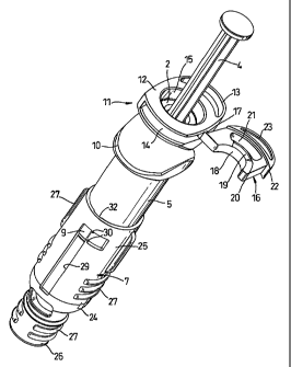
The syringe to be used in the holder is of the usual
form, having a capsule 1 with an outward radial flange 2 at
its rear end. A needle 3, initially with a cap shown in
outline, projects from its forward end, and a plunger 4
projecting from the rear end is urged forwards in use to
express a dose within the capsule through the needle 3.
CA 02445317 2003-10-24
WO 02/087670 PCT/GB02/01955
The holder has three main components, namely a barrel
5, a helical spring 6 within the barrel, and a needle
protection sleeve 7 which telescopes over the forward end
of the barrel.
5 The barrel 5 is straight cylindrical over most of its
length. At its forward end there are two diametrically
opposed external splines 8 of right-angled triangular
cross-section, aligned parallel with the axis of the
barrel,'and with one side radial to the barrel and the
other almost tangential thereto. Both radial sides face in
the same circumferential direction. Midway between these
splines 8 on the outer surface of the barrel and set back a
bit from the end is a shallow square projection 9.
About two thirds the length of the barrel back from
its forward end there is a generally elliptical external
flange 10, for ease of handling the device in use.
The barrel has an asymmetric cup formation 11 at its
rear end to receive and locate the rear end of the syringe.
A flange 12 is thick and is extended radially over an arc
of about 90° by a curved loop 13. Opposite this, a slot 14
is provided between the upper and lower faces of the flange
12, open to the socket 15 in which the flange 2 of the
syringe seats. When that is properly in position, the rear
face of the flange 2 is just beyond the slot 14 in the
CA 02445317 2003-10-24
WO 02/087670 PCT/GB02/01955
6
forwards direction. A gate 16 is hinged by a thin web 17
to the side of the flange 12 and 90° from the crown of the
loop 13 and can be swung from the retracted position shown
to enter and become captive in the slot 14, at the same
time making the syringe captive in the barrel 5. The gate
is generally D-shaped with the hinge at one corner, but the
straight part of the D has a semicircular out-out 18 which
allows it to half-surround the plunger 4 while the adjaoent
part of the body of the gate overlies the flange 2 and
blocks rearward movement of the syringe.
The gate 16 snap fastens in the slot 14. It is
largely of a thickness equal to the width of the slot 14,
but around the crown of the cut-out 18 there is a
correspondingly curved ramp 19 ending in a step 20 back to
the main body of the gate. As that is closed, the ramp
wedges the slot 14 a bit wider, but once the step 20
reaches the socket 15 the slot 14 closes against the gate
and that is secure.
Beyond the ramp 19 from the cut-out 18 there is a
curved slot 21, and beyond that the gate steps out into a
thicker section 22 with a loop 23 so that, when closed,
there is a match with the diametrically opposite loop 13.
The needle protector sleeve 7 is a cylindrical member
reducing at a shoulder 24 forward of its mid-length.. Both
CA 02445317 2003-10-24
WO 02/087670 PCT/GB02/01955
7
the larger and the reduced diameter portions 25 and 26 have
external ribs 27 for a good grip. Internally, there are
tabs 28 projecting inwardly and forwardly from the shoulder
24, which is stepped on the inside rather than sloping as
on the outside. The larger diameter portion 25 has an Z-
shaped slot 29 with the long arm extending over most of its
length, and the short arm being part circumferential at the
rear end. The basic width corresponds to that of the
projection 9, and at the entrance to the short arm there
are small lugs 30 which-make for a snap action entry of the
projection 9 into that part of the slot. Two diametrically
opposed splines 31 are formed internally of the larger
diameter portion 25 and are positioned to co-operate with
the splines 8 when the projection 9 enters the short arm of
the slot 29.
The device is assembled by inserting the spring 6 into
the forward end of the barrel 5 and then pressing that
forward end into the rear portion of the protector sleeve 7
with the projection 9 aligned with the long arm of the slot
29. There is enough flexibility and resilience for this to
be a snap action, and to ease the fitting there is a
shallow longitudinal channel 32 on the inside of the sleeve
from its rear end to the slot 29 to accommodate the
projection 9 to some extent, although it will still have to
CA 02445317 2003-10-24
WO 02/087670 PCT/GB02/01955
8
be forced through. Once the projection 9 is in the slot 29
the two members 5 and 7 are mutually captive. The holder
is then ready to receive the syringe, which is entered into
the rear of the barrel 5 until its flange 2 seats in the
socket 15, to be trapped as described.
Prior to use, the protector sleeve 7 is moved
rearwardly against the spring 6, which bears on the inner
step in the shoulder 24, until the tabs 28 snap past the
enlarged rear end of the needle cap. When the sleeve 7 is
let go, it is moved forwards again by the spring 6 and the
tabs 28 ease the needle cap off. But when that cap is
removed the tip of the needle 3 remains shrouded by the
reduced diameter portion 26. The device is now ready to
use.
The forward end of the sleeve 7 is applied to the
patient's skin and pressure is exerted. The needle 3
penetrates as the sleeve 7 is pushed back. The amount the
needle 3 projects is dependent on the length of the portion
26 of the sleeve 7 and the stop provided by the outer step
in the shoulder 24, up against which the end of the barrel
5 comes. The projection 9 meets the forward end of the
slot 29 at the same time. The spring 6, whose forward end
abuts the inner step in the shoulder 24, is compressed.
CA 02445317 2003-10-24
WO 02/087670 PCT/GB02/01955
9
The plunger 4 is then pressed to eject the dose through the
needle 3.
On withdrawal, the spring 6 exerts itself and pushes
the sleeve 7 forwards so that the needle 3 is shrouded.
The sleeve 7 is then pulled right forwards, if not already
moved there by spring action, and twisted so that the
projection 9 enters the short arm of the slot 39. As it
seats, the splines 8 and 18 snap past each other, capturing
the sleeve 7 in that position. So the needle 3 is not re-
exposable, and the device is safe for disposal.
The snap action of the splines 8 and 18 is more
positive than that of the projection 9 past the lugs 30,
which could be omitted. Alternatively or in addition they
could be made non-return in relation to the projection 9,
rendering the splines 8 and 18 redundant or complementing
those splines.